Chapter 7
Centralized Data Policies
This chapter covers the following topics:
Centralized Data Policy Overview: This section reviews the basics of centralized data policies and the directionality of policies when applied to a WAN Edge router.
Centralized Data Policy Use Cases: This section explores several different sets of common business requirements and explores how network administrators can use centralized data policies to solve for these use cases.
Use Case 10: Direct Internet Access for Guest Users: This section covers a simple data policy to ensure that only publicly routable packets are forwarded to the Internet. This section also reviews how to build a centralized data policy with the vManage GUI.
Use Case 11: Direct Cloud Access for Trusted Applications: This section covers the use of a centralized data policy to change the forwarding path for a specific application and provide direct Internet egress.
Use Case 12: Application-Based Traffic Engineering: This section reviews different methods for performing traffic engineering of flows that traverse the SD-WAN fabric.
Use Case 13: Protecting Corporate Users with a Cloud-Delivered Firewall: This section reviews the use of service insertion to redirect traffic to Cisco Umbrella Secure Internet Gateway.
Use Case 14: Protecting Applications from Packet Loss: This section covers two different methodologies to reconstruct data flows that have been affected by lossy transport networks.
Building on the examples in Chapter 6, “Centralized Control Policies,” this chapter will focus on centralized data policies. Unlike centralized control policies that manipulate the routing information in the data plane, centralized data policies are used to override the normal forwarding decisions that would be made by the router and instead follow a specific set of forwarding instructions. These policies can be implemented for a specific flow or application or for all of the traffic at a site. This incredible control provided to network administrators is why centralized data policies are often referred to as “policy-based routing on steroids.” However, unlike traditional policy-based routing, centralized data policies are much easier to administer because they are all configured and applied centrally.
Centralized Data Policy Overview
Centralized data policies are a powerful tool that allows administrators to override the normal forwarding actions that would occur in the data plane and specify a different set of actions that should be taken instead. As the use cases in this chapter will show, those new actions could be as simple as dropping a packet, redirecting a flow down a specific path or to a specific service, providing additional data plane services to accelerate data transfers and protect from packet loss, or any combination of these actions.
As discussed in Chapter 5, “Introduction to Cisco SD-WAN Policies,” each type of policy has a specific directionality to it. In the case of centralized data policies, policies can either be applied to traffic that is originating “from-tunnel,” traffic that is originating “from-service,” or traffic that is traversing the WAN Edge router in both directions. Figure 7-1 illustrates these directions.
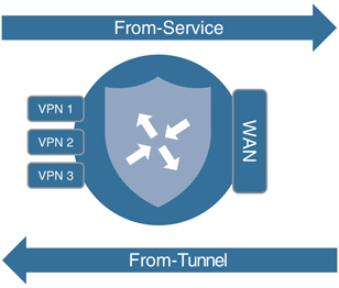
Figure 7-1 Data Policy Directionality
Centralized Data Policy Use Cases
In the following sections, we examine several different sets of common business requirements and explore how network administrators can use centralized data policies to solve for these use cases. These use cases are meant to address common applications of centralized data policies as well as to provide an illustrative review of many of the building blocks of centralized data policies, from which network administrators can build their own policies to accomplish their own objectives. The examples in this chapter will continue to build on the network and the examples discussed in Chapter 6. To that end, Figure 7-2 illustrates the topology we will be discussing throughout this chapter, and you can find the centralized policy that will be used as the starting point in Example 6-24 at the end of the previous chapter.
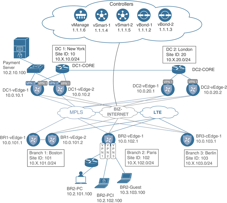
Figure 7-2 Network Topology for Chapter 7
Although the network featured in Figure 7-2 is identical to the network used in Chapter 6, there are several changes present in this diagram to highlight some elements that will be used throughout this chapter. Specifically, Branch 2 is drawn in greater detail to illustrate the end hosts that reside in each of the Corporate, PCI, and Guest Service VPNs. Also note that the Payment Processing Server is located in Data Center 1, in the PCI VPN. As noted in Chapter 6, the service-side addressing in this network follows the 10.X.Y.0/24 structure, where X signifies the service-side VPN and Y signifies the site ID. For the first few use cases in this chapter, we will be focusing on VPN 1, and that service-side addressing will be in the 10.1.Y.0/24 address blocks. This topology will allow us to explore different types of policies, how they interact with the SD-WAN fabric, and how network administrators can apply these policies to solve business problems.
Use Case 10: Direct Internet Access for Guest Users
The first use case we will be discussing builds on the VPN membership policy we explored in Chapter 6 to provide Internet access to guest users. In Chapter 6, Example 6-20 showed that users in the Guest VPN on BR2-vEdge1 are able to reach the Internet but not able to reach the other branches. Although true, this is not the complete story, as all of the traffic in the VPN is following the default route. Even traffic that is destined to addresses that are not reachable across the public Internet, such as private (RFC 1918) addresses, is being forwarded out onto the public Internet, where it is eventually dropped, as shown in Example 7-1.
Example 7-1 Connectivity from the Guest VPN on BR2-vEdge1
!
! BR2-vEdge1 is able to reach the public internet from the Guest VPN
!
BR2-vEdge-1# ping vpn 3 8.8.8.8 count 3
Ping in VPN 3
PING 8.8.8.8 (8.8.8.8) 56(84) bytes of data.
64 bytes from 8.8.8.8: icmp_seq=1 ttl=53 time=18.2 ms
64 bytes from 8.8.8.8: icmp_seq=2 ttl=53 time=16.0 ms
64 bytes from 8.8.8.8: icmp_seq=3 ttl=53 time=17.4 ms

--- 8.8.8.8 ping statistics ---
3 packets transmitted, 3 received, 0% packet loss, time 2001ms
rtt min/avg/max/mdev = 16.018/17.259/18.289/0.951 ms
!
! BR2-vEdge1 is unable to reach BR3-cEdge1 in the Guest VPN as expected
!
BR2-vEdge-1# ping vpn 3 10.3.103.1 count 3
Ping in VPN 3
PING 10.3.103.1 (10.3.103.1) 56(84) bytes of data.

--- 10.3.103.1 ping statistics ---
3 packets transmitted, 0 received, 100% packet loss, time 1999ms
!
! Looking at the traceroute to 10.3.103.1 and the routing table, it is clear
! that BR2-vEdge1 is using the default route to the internet to forward this
! packet, rather than dropping the traffic.
!
BR2-vEdge-1# traceroute vpn 3 10.3.103.1
Traceroute  10.3.103.1 in VPN 3
traceroute to 10.3.103.1 (10.3.103.1), 30 hops max, 60 byte packets
 1  * * *
 2  100.64.102.1 (100.64.102.1)  1.243 ms  1.260 ms  1.320 ms
 3  192.168.255.1 (192.168.255.1)  3.809 ms  4.031 ms  4.070 ms
 4  192.168.1.1 (192.168.1.1)  4.320 ms  4.359 ms  4.469 ms
 5  * * *
 6  * * *
<<<Omitted for Brevity>>>
29  * * *
30  * * *
!
! The protocol of ‘nat’ and a nexthop-vpn of 0 indicate that this route is
! being used to nat traffic out to the transit interfaces in VPN 0 for access
! to the internet.
!
BR2-vEdge-1# sho ip route vpn 3 10.3.103.1 detail
Codes Proto-sub-type:
  IA -> ospf-intra-area, IE -> ospf-inter-area,
  E1 -> ospf-external1, E2 -> ospf-external2,
  N1 -> ospf-nssa-external1, N2 -> ospf-nssa-external2,
  e -> bgp-external, i -> bgp-internal
Codes Status flags:
  F -> fib, S -> selected, I -> inactive,
  B -> blackhole, R -> recursive

“”--------------------------------------------
 VPN 3      PREFIX 0.0.0.0/0
--------------------------------------------
proto           nat
 distance       1
 metric         0
 uptime         3:23:26:52
 nexthop-ifname ge0/0
nexthop-vpn     0
 status         F,S
As Example 7-1 shows, bandwidth is being wasted by allowing packets to be forwarded out of the Internet interfaces that are destined to private, internal addresses, and therefore cannot possibly reach their destinations across the Internet. Rather than uselessly forwarding these packets out to the Internet, a centralized data policy could be constructed to drop them instead.
The first step in the process of creating a centralized data policy is to create the data-prefix-lists that will be necessary. The menu for creating lists can be found in the upper-right corner of the Configuration > Policies screen under the blue Custom Options menu, as shown in Figure 7-3.
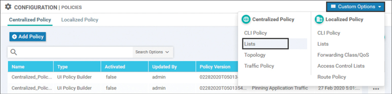
Figure 7-3 Creating Lists for Use in a Centralized Policy
The first list that will be needed for this centralized data policy is a Data Prefix list of Bogon addresses. The following is per RFC 3871:
A “Bogon” (plural: “bogons”) is a packet with an IP source address in an address block not yet allocated by IANA or the Regional Internet Registries (ARIN, RIPE, APNIC…) as well as all addresses reserved for private or special use by RFCs. See [RFC3330] and [RFC1918].
Filtering out packets that are destined to networks that cannot exist on the public Internet will help to save resources by not forwarding unnecessary packets. A data-prefix-list to accomplish this filtering can be created by selecting the Data Prefix list type, then clicking the blue + New Data Prefix List button. In the Data Prefix List configuration window, a list name and the necessary data prefixes are configured, as seen in Figure 7-4.
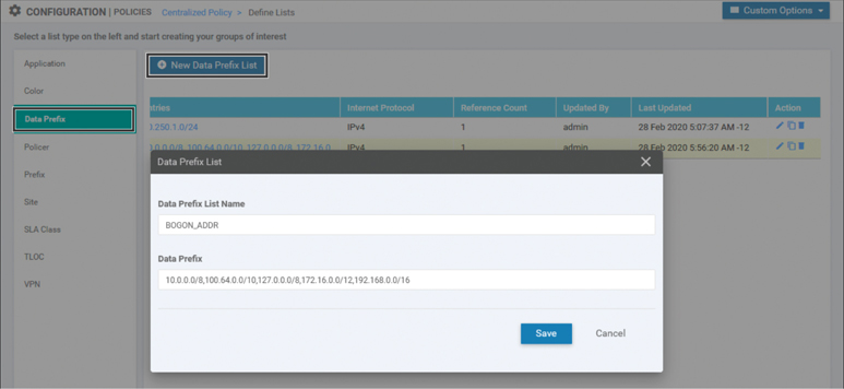
Figure 7-4 Configuring Data Prefix Lists
As Figure 7-4 indicates, this data prefix list includes RFC 1918 ranges, the 127.0.0.0/8 home range, and the 100.64.0.0/10 carrier-grade NAT range. None of these ranges are publicly routable, and therefore traffic that is destined to any of these destinations should not be forwarded to the Internet. In order to build a centralized policy to accomplish this filtering, the next step would be to build the data policy itself. Start by selecting Traffic Policy from the Custom Options drop-down menu shown in Figure 7-3. From the Traffic Policy screen, you see three tabs across the top: Application Aware Routing, Traffic Data, and Cflowd. To create a new traffic data policy, select the Traffic Data tab and then select the Create New option under the Add Policy menu, as shown in Figure 7-5.
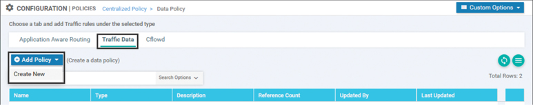
Figure 7-5 Creating a New Centralized Data Policy
The first step in creating the new policy is to add a sequence type by clicking the + Sequence Type button, as shown in Figure 7-6. There are many different sequence types available in a centralized data policy, including Application Firewall, QoS, Service Chaining, and Traffic Engineering. These different sequence types expose a limited subset of the available actions to the administrator and attempt to highlight the different actions that may be used to address some of these use cases. The Custom sequence type provides access to all of the action options in the GUI, and many administrators prefer to use this sequence type for all use cases. For this example, select the Custom sequence type, as indicated in Figure 7-6.
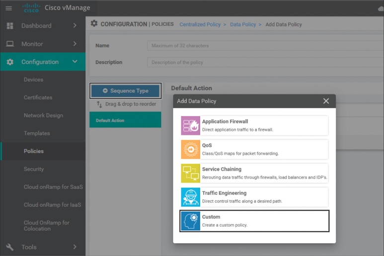
Figure 7-6 Add a New Sequence Type to the Data Policy
This new policy will need to consist of two different sequences, as shown in Figure 7-7. The first sequence will match the packets destined to the addresses in the Bogon data-prefix-list and drop them. There is an additional Counter action that is applied to this sequence as well. A counter named GUEST_DROPPED_PKTS is then specified to track the number of packets that match this sequence. While counters in and of themselves don’t provide any impact to how traffic is forwarded, they do provide a useful tool when evaluating and troubleshooting policies.
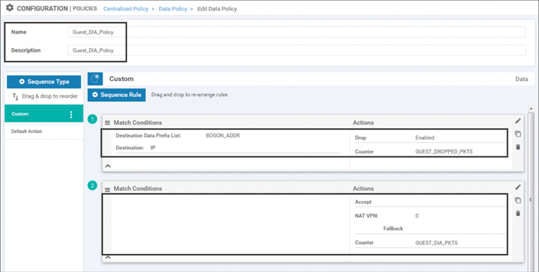
Figure 7-7 Guest Internet Access Data Policy
The second sequence will send all other packets out of the VPN 0 interfaces to the underlay. Matching all other packets is accomplished by not specifying any matching criteria at all in this sequence rule. There are two actions specified in the second sequence rule: NAT VPN and Counter. The NAT VPN action allows us to specify traffic that should be leaked to VPN 0 and forwarded out of a NAT-enabled interface. The VPN argument for this action is always VPN 0. You cannot use the NAT VPN action to leak between service-side VPNs; the NAT VPN action can only be used to leak between a Service VPN and VPN 0 for the purpose of Direct Internet Access (DIA). There is also an optional argument of Fallback, which is not selected in this case. Fallback will be discussed in greater detail in Use Case 11.
For ease of visibility, a counter called GUEST_DIA_PKTS is added to the action statements in this sequence that will count the number of packets forwarded by the second sequence.
Once the necessary sequences have been added and a name and description have been added, the centralized data policy can be saved. The next step in the configuration process is to add this data policy to our existing centralized policy from Chapter 6. The easiest way to do that is to select the centralized policy and create a copy of it by selecting that option from the drop-down menu on the right side of the screen, as shown in Figure 7-8.
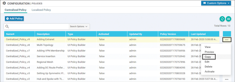
Figure 7-8 Creating a Copy of a Centralized Policy
Once the new policy is created, it can be edited by selecting the Edit option from the same drop-down menu on the newly copied policy. As shown in Figure 7-9, the Edit Policy page has three main tabs at the very top: Policy Application, Topology, and Traffic Rules. Selecting the Traffic Rules tab reveals three more sub-tabs—Application Aware Routing, Traffic Data, and Cflowd—just as there were when the data policy was initially created. After selecting the Traffic Data sub-tab, select the Add Policy menu in order to import the existing policy as indicated in Figure 7-9.
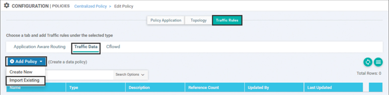
Figure 7-9 Edit Policy Window
When prompted, select the previously created Guest_DIA_Policy, as shown in Figure 7-10, and click the Import button.
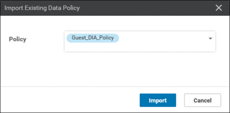
Figure 7-10 Importing the Guest_DIA_Policy into the Centralized Policy
Now that the Guest DIA policy is referenced in the centralized policy, the last step in the creation of the centralized policy is to specify where the data policy should be applied by clicking the +New Site List and VPN List button. This policy is applied to the Site ID list (BranchOffices), the VPN List (GUEST_ACCESS_VPN), and the direction (From Service), as shown in Figure 7-11.
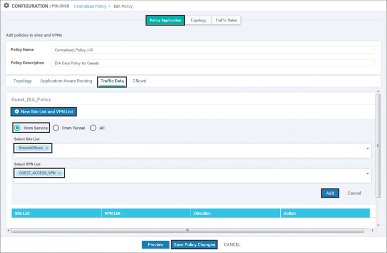
Figure 7-11 Applying the New Data Policy
These configurations are saved by selecting the Add button. Once this step is completed, the policy should be saved and activated on the SD-WAN fabric. Example 7-2 shows the relevant changes to the configuration from the full policy that was displayed in Example 6-24.
Example 7-2 Guest Internet Access Policy
policy
 ! <<<No changes were made to the control policies or VPN membership policies,
 ! and they are omitted for brevity. The full configuration of those policies
 ! can be found in Example 6-24. >>>
 !
 ! The newly created data policy is specified below. Note that the vpn-list
 ! the policy is applied to is specified in the policy definition, not in the
 ! apply-policy section at the end.
!
 data-policy _GUEST_ACCESS_VPN_Gu_-1821888509
  vpn-list GUEST_ACCESS_VPN
    sequence 1
     match
     destination-data-prefix-list BOGON_ADDR
    !
    action drop
     !
      ! The count action and counter are specified here, and are used for
      ! monitoring and troubleshooting.
      count GUEST_DROPPED_PKTS_-837951389
     !
    !
    ! In the second sequence, all other packets are forwarded using the
    ! “nat use-vpn 0” syntax and also counted. Note that the matching criteria
    ! of any source address were automatically inserted by vManage.

    sequence 11
    match
     source-ip 0.0.0.0/0
    !
    action accept
     nat use-vpn 0
      count GUEST_DIA_PKTS_-837951389
     !
    !
  default-action drop
 !
 lists
 ! <<<Some lists without changes from Example 6-24 are omitted for brevity>>>
 !
  data-prefix-list BOGON_ADDR
   ip-prefix 10.0.0.0/8
   ip-prefix 100.64.0.0/10
   ip-prefix 127.0.0.0/8
   ip-prefix 172.16.0.0/12
   ip-prefix 192.168.0.0/16
 !
  site-list BranchOffices
   site-id 100-199
  !
  vpn-list GUEST_ACCESS_VPN
   vpn 3
  !
!
apply-policy
 site-list Europe_Branches
  control-policy Euro_Reg_Mesh_with_FW_MultiTopo out
 !
 ! The newly created policy is applied to the Site List “BranchOffices”
 ! with the direction “from-service”.
 !
 site-list BranchOffices
  data-policy _GUEST_ACCESS_VPN_Gu_-1821888509 from-service
  control-policy Branch_Extranet_Route_Leaking in
  vpn-membership vpnMembership_1710051916
 !
 site-list DCs
  control-policy DC_Inbound_Control_Policy in
 !
 site-list North_America_Branches
  control-policy North_America_Reg_Mesh_with_FW out
 !
!
The structure of the data policy, as seen in Example 7-2, is very similar to the structure of the control policies discussed in Chapter 6. Each policy is a structured sequence of match statements that specify the criteria and a list of actions to take. In this policy, the first sequence is matching packets destined to the addresses in the BOGON_ADDR list. These packets are dropped and counted with the counter GUEST_DROPPED_PKTS. The second sequence matches all other traffic and forwards it out of the VPN 0 interfaces to the Internet using the nat use-vpn 0 command. This traffic is also being tracked with the counter GUEST_DIA_PKTS. In this particular policy, the setting of the default action is irrelevant, because all traffic that wasn’t matched by sequence 1 will be matched by sequence 11.
Note
The name of the data policy that was configured in Figure 7-7 was Guest_DIA_Policy, whereas the name of the policy that is rendered in the CLI is _GUEST_ACCESS_VPN_Gu_-1821888509. This name is a concatenation of the VPN list that the policy is applied to, the name of the policy, and a string from vManage to ensure uniqueness. While these additional strings of numbers may make it harder at first glance to follow the naming of the policies, they ensure that the user naming structure and the concatenated names don’t overlap.
Users may also note that that counter names are concatenated with strings as well, again ensuring that if the same counter name is used in multiple policies, it will remain unique.
The effects of this policy can be seen in Example 7-3, where users can still access the same resources on the public Internet, but traffic that should not be forwarded to the Internet is dropped instead of consuming that bandwidth.
Example 7-3 Effects of Data Policy on Users in the Guest VPN
!
! As the centralized data policy is enforced on the WAN-Edge router, the policy
! is encoded as an OMP update by the vSmart controller and advertised to the
! WAN-Edge. The policy is viewable with the “show policy from-vsmart” command.
!
BR2-vEdge-1# show policy from-vsmart
from-vsmart data-policy _GUEST_ACCESS_VPN_Gu_-1821888509
 direction from-service
 vpn-list GUEST_ACCESS_VPN
  sequence 1
   match
    destination-data-prefix-list BOGON_ADDR
   action drop
    count GUEST_DROPPED_PKTS_-837951389
  sequence 11
   match
    source-ip 0.0.0.0/0
   action accept
    count GUEST_DIA_PKTS_-837951389
    nat use-vpn 0
    no nat fallback
  default-action drop
from-vsmart lists vpn-list GUEST_ACCESS_VPN
 vpn 3
from-vsmart lists data-prefix-list BOGON_ADDR
 ip-prefix 10.0.0.0/8
 ip-prefix 100.64.0.0/10
 ip-prefix 127.0.0.0/8
 ip-prefix 172.16.0.0/12
 ip-prefix 192.168.0.0/16
BR2-vEdge-1#
BR2-vEdge-1#
!
! The counters that are configured in the policy can be seen with the “show policy
! data-policy-filter” command. Before any traffic is sent, both counters are 0.
!
BR2-vEdge-1# show policy data-policy-filter
data-policy-filter _GUEST_ACCESS_VPN_Gu_-1821888509
 data-policy-vpnlist GUEST_ACCESS_VPN
 vpn 3
  data-policy-counter GUEST_DIA_PKTS_-837951389
   packets 0
   bytes   0
  data-policy-counter GUEST_DROPPED_PKTS_-837951389
   packets 0
   bytes   0
!
! After sending four packets to 8.8.8.8, the GUEST_DIA_PKTS counter has
! incremented to 4.
!
BR2-vEdge-1# ping vpn 3 8.8.8.8 count 4
Ping in VPN 3
PING 8.8.8.8 (8.8.8.8) 56(84) bytes of data.
64 bytes from 8.8.8.8: icmp_seq=1 ttl=53 time=22.2 ms
64 bytes from 8.8.8.8: icmp_seq=2 ttl=53 time=26.2 ms
64 bytes from 8.8.8.8: icmp_seq=3 ttl=53 time=21.4 ms
64 bytes from 8.8.8.8: icmp_seq=4 ttl=53 time=22.3 ms
--- 8.8.8.8 ping statistics ---
4 packets transmitted, 4 received, 0% packet loss, time 3003ms
rtt min/avg/max/mdev = 21.414/23.062/26.235/1.874 ms
BR2-vEdge-1#
BR2-vEdge-1# show policy data-policy-filter
data-policy-filter _GUEST_ACCESS_VPN_Gu_-1821888509
 data-policy-vpnlist GUEST_ACCESS_VPN
  data-policy-counter GUEST_DIA_PKTS_-837951389
   packets 4
   bytes   408
  data-policy-counter GUEST_DROPPED_PKTS_-837951389
   packets 0
   bytes   0
!
! After sending five packets to 10.3.103.1, the GUEST_DROPPED_PKTS counter has
! incremented to 5.
!
BR2-vEdge-1# ping vpn 3 10.3.103.1 count 5
Ping in VPN 3
PING 10.3.103.1 (10.3.103.1) 56(84) bytes of data.
--- 10.3.103.1 ping statistics ---
5 packets transmitted, 0 received, 100% packet loss, time 3999ms
BR2-vEdge-1# show policy data-policy-filter
data-policy-filter _GUEST_ACCESS_VPN_Gu_-1821888509
 data-policy-vpnlist GUEST_ACCESS_VPN
  data-policy-counter GUEST_DIA_PKTS_-837951389
   packets 4
   bytes   408
  data-policy-counter GUEST_DROPPED_PKTS_-837951389
   packets 5
   bytes   510
BR2-vEdge-1#
As shown in Example 7-3, the relevant portion of the data policy has been sent to the WAN Edge from the vSmart controllers. Note that this is different than the behavior for centralized control policies. Example 7-2 shows that there is a centralized control policy and a VPN membership policy that has also been applied to the site list BranchOffices; however, only the data policy is visible in the output of show policy from-vsmart. This is because the control policies are enforced on the vSmarts directly and therefore have no reason to be advertised to the WAN Edges. The data policies, however, are enforced on the WAN Edges and therefore need to be advertised to the WAN Edges.
The show policy data-policy-filter command, as seen in Example 7-3, shows how network administrators can use counters to monitor how flows are being forwarded across the network. The first time the command is run, all of the counters display zeros, as there have been no packets matched by the policy yet. After pinging a destination on the Internet with four packets, the GUEST_DIA_PKTS counter reflects that four packets were forwarded. Lastly, the five pings sent to a Bogon address are reflected in the GUEST_DROPPED_PKTS counter.
These effects can also be seen using the Simulate Flows tool that can be found under the Troubleshooting menu in the Monitor > Network > [Device] page that was discussed in Chapter 6. When simulating flows that are destined to 8.8.8.8, as shown in Figure 7-12, there is only a next-hop address and an interface specified for the flow. When this output is contrasted against similar output in Figure 6-37, it is clear that this output is lacking the remote system IP, encapsulation, and color that was displayed in that output. This output indicates that the flow is not going to be forwarded across the SD-WAN fabric, but instead is going to egress from the ge0/0 interface, with the next-hop address of 100.64.102.1, which is the upstream ISP router connected to BR2-vEdge1.
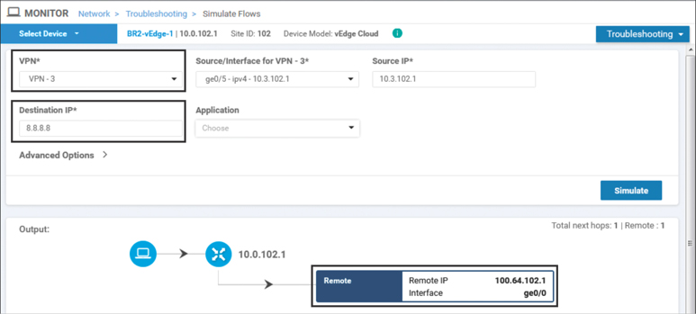
Figure 7-12 Simulate Flows Output to 8.8.8.8 from VPN 3 Shows That Traffic Is Forwarded to the Internet
On the other hand, when Simulate Flows is performed for traffic going to 10.3.103.1, the unambiguous results are displayed in Figure 7-13.
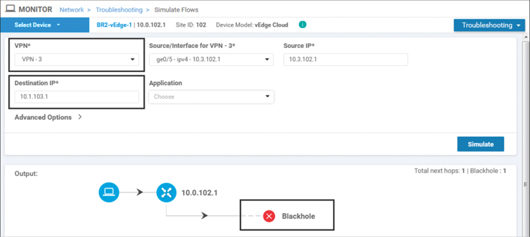
Figure 7-13 Simulate Flows Output to 10.3.103.1 from VPN 3 Shows That Traffic Is Blackholed
Use Case 10 Review
In this use case, a simple data policy was created and applied to VPN 3. Through this example, we have seen how data policies can be used to manipulate the forwarding path of traffic. The simple data policy for the guest user VPN illustrates that the structure of data policies is very similar to the structure of control policies, consisting of match and action sequences. While the actual purpose of this policy—dropping packets destined to a specific destination—is relatively straightforward, it is easy to conceive how other policies can be used for much more intricate tasks. For example, it would be trivial to drop traffic destined to a specific port while permitting traffic to other ports with a data policy and impossible to do so with a control policy.
Use Case 11: Direct Cloud Access for Trusted Applications
In addition to providing Internet access for guest users, many organizations are starting to leverage local Internet breakout for employees as well. However, there are significant security implications that come with permitting Direct Internet Access from every branch office to the entirety of the Internet. Detailed discussions on the security features that are built in to the WAN Edge routers can be found in Chapter 10, “Cisco SD-WAN Security.” However, one of the ways that organizations can choose to limit the security implications of these choices is to restrict direct access to the Internet from the branch to certain applications or destinations that are deemed to be trusted or lower risk. Such applications may include enterprise services such as Office 365, Google Apps, and Salesforce.com. These types of policies are commonly referred to as Direct Cloud Access, in contrast to Direct Internet Access policies, which permit unbridled access to all outside destinations.
In this use case, we will build a data policy that allows users to access a specific trusted application, Cisco WebEx, directly from the local branch, while still requiring all other Internet traffic to traverse the main security perimeter through the data centers. Figure 7-14 outlines this traffic pattern for corporate users.

Figure 7-14 Desired Forwarding Paths Are Different per Application
Before the policy is applied, all of the traffic from the corporate users behind BR2-vEdge1 traverse through DC2 to reach the public Internet. This can be seen using the Simulate Flows tool in Figure 7-15. The Remote System IP of the device, where the traffic is going to be forwarded, is listed as 10.0.20.1. In this output, the application webex-meeting is specified in the flow criteria.
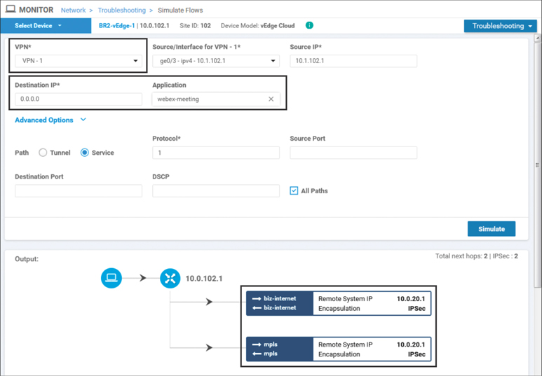
Figure 7-15 WebEx Traffic from Users in VPN 1 Would Be Forwarded to DC2 WAN Edge Routers
Note that with Figure 7-15 and Figure 7-16, different applications are specified, and the destination address of 0.0.0.0 is used. By not specifying a specific address, the tool can leverage the forwarding decisions that would be made for any traffic following the default route in the routing table. However, if a destination address was specified, that would be taken into account when determining the ultimate forwarding path of the flow. By specifying a combination of different applications, DSCP markings, addresses, ports, and/or protocols, the Simulate Flows tool can become a particularly powerful tool for network administrators to understand how the traffic is flowing through the network.
In Figure 7-15 and Figure 7-16, both WebEx traffic and YouTube traffic would be forwarded across the SD-WAN fabric to DC2-vEdge1, indicated in the figures by the remote system IP address of 10.0.20.1. These application flows would be load-shared across both the mpls and biz-internet paths, as indicated by the multiple paths in the output. These outputs, taken before the updated policy is applied, show that the forwarding path for both applications is the same.
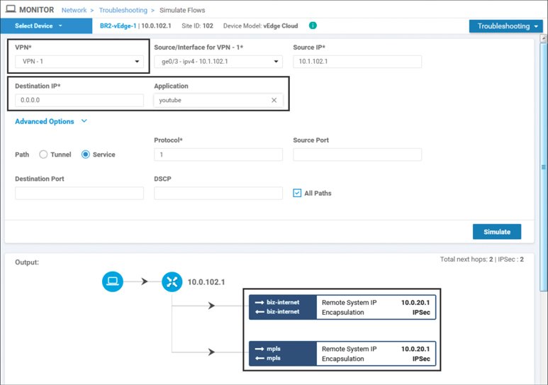
Figure 7-16 YouTube Traffic from Users in VPN 1 Would Be Forwarded to the DC2 WAN Edge Routers
In order to meet the requirements of this use case and forward the WebEx traffic directly out to the Internet, while continuing to backhaul all other traffic, including YouTube, across to the data centers, the centralized policy from Example 7-2 is modified to include a new data policy that matches the WebEx application and forwards it out the local interface, as shown in Example 7-4.
Example 7-4 Corporate Direct Cloud Access Policy
policy
 ! <<<No changes were made to the control policies or VPN membership policies,
 ! and they are omitted for brevity. The full configuration of those policies
 ! can be found in Example 6-24. >>>
 !
 ! The data policy below specifies two different VPNs, and each VPN has an
 ! individual set of sequences with different rules. However, the entire policy
 ! is applied to the site list.
 !
data-policy _CorporateVPN_Branch__1962746902
 vpn-list CorporateVPN
    sequence 1
     ! In the new sequence for the CorporateVPN, we are matching a specific app-list
     ! for the TRUSTED_APPS. The action (nat use-vpn 0) is the same action that was
     ! used for guest internet access. A new counter was also created and applied
     ! for monitoring.
    match
     app-list TRUSTED_APPS
      source-ip 0.0.0.0/0
     !
      ! The nat fallback configuration specifies the forwarding behavior in the event
      ! that there are no local interfaces that are operational and configured for NAT
     action accept
      nat use-vpn 0
      nat fallback
      count CORP_DCA_-209017211
     !
    !
   ! All non-webex traffic will be matched by the default action and forwarded as
   ! normal across the fabric.
   !
  default-action accept
 !
 ! The Guest_DIA_Policy that was configured as part of Use Case 10 is unchanged.
 !
  vpn-list GUEST_ACCESS_VPN
   sequence 1
     match
      destination-data-prefix-list BOGON_ADDR
     !
     action drop
      count GUEST_DROPPED_PKTS_-1348283274
     !
    !
    sequence 11
     match
      source-ip 0.0.0.0/0
     !
     action accept
      nat use-vpn 0

      count GUEST_DIA_PKTS_-1348283274
     !
    !
  default-action drop
 !
 lists
 ! <<<Some lists without changes are omitted for brevity>>>
 !
  app-list TRUSTED_APPS
   app webex-meeting
   app webex_weboffice
   app webex
  !
  vpn-list CorporateVPN
   vpn 1
  !
  vpn-list GUEST_ACCESS_VPN
   vpn 3
  !
 !
!
apply-policy
 site-list Europe_Branches
  control-policy Euro_Reg_Mesh_with_FW_MultiTopo out
 !
site-list BranchOffices
 data-policy _CorporateVPN_Branch__1962746902 from-service
  control-policy Branch_Extranet_Route_Leaking in
  vpn-membership vpnMembership_373293275
 !
 site-list DCs
  control-policy DC_Inbound_Control_Policy in
 !
 site-list North_America_Branches
  control-policy North_America_Reg_Mesh_with_FW out
 !
!
Example 7-4 shows the modifications to the data policy that were made in order to implement the Direct Cloud Access functionality for corporate users. This builds on the policy that was created in Use Case 10 and adds support for corporate users in a second VPN (VPN 1) with an entirely different set of rules. It is important to understand that these two sets of sequences for the two different VPNs have been concatenated into a single data policy when activated on the vSmart controller, even though they are administered in vManage as two separate data policies (as shown in Figure 7-17). In this case, the _CorporateVPN_Branch__1962746902 policy affects the VPNs specified by both the CorporateVPN and GUEST_ACCESS_VPN lists, albeit with different policies specified in their respective sequence sets. Furthermore, there is no reference to the VPNs that the data policy is applied to in the apply-policy stanza at the end of the centralized policy; this is configured by the VPN lists referenced in the data policies.

Figure 7-17 Apply Policy Configuration Showing That Corporate and Guest Data Policies Are Separate Policies
Once the policy is activated, the results can be validated using the Simulate Flows tool. As shown in Figure 7-18, WebEx traffic now egresses directly to the Internet. This flow pattern is different from what was observed for WebEx traffic before the policy was applied in Figure 7-15, and it’s similar to what was seen for traffic in the Guest VPN in Figure 7-12.
Conversely, the forwarding pattern for YouTube traffic, as shown in Figure 7-19 after the policy is activated, is the same as in Figure 7-16 before the policy was activated. All of the YouTube traffic is going to be forwarded across the fabric to the data center and be inspected by the traditional security perimeter there.
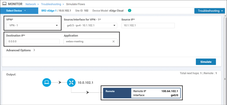
Figure 7-18 WebEx Traffic from Users in VPN 1 Would Egress Directly to the Internet
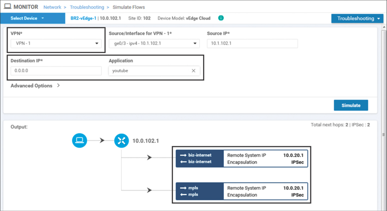
Figure 7-19 YouTube Traffic from Users in VPN 1 Would Continue to Be Forwarded to the DC2 WAN Edge Routers
As highlighted in Figure 7-7 and Example 7-4, the nat use-vpn 0 action has an optional configuration argument called nat fallback. This argument allows the administrator to specify the desired behavior in the event of a failure. With nat fallback enabled, in the event that all of the NAT-enabled VPN 0 interfaces on the local vEdge were to be in a non-operational state, the traffic would follow the forwarding path determined by the routing table. This would typically mean that the traffic traverses across the fabric and egress at a different site (such as a data center). Figure 7-20 illustrates this traffic pattern.

Figure 7-20 Illustrated NAT Fallback Data Path
In Use Case 10, the nat-vpn 0 action is configured for guest Internet access traffic without nat fallback enabled. Should all of the local interfaces with NAT configured go down, then guest traffic will not fall back and be forwarded across the SD-WAN fabric and will instead be blackholed. In this use case, the data policy for Corporate VPN does have the nat fallback option configured, and this allows for the WebEx traffic to be backhauled through the data center in the event of a failure of the local Internet connection. Example 7-5 shows both traffic patterns.
Example 7-5 also introduces a new set of tools for monitoring the forwarding decision of flows from the CLI: show policy service-path and show policy tunnel-path. These two show commands are the CLI corollaries to the Simulate Flows tool that has been shown inside of the vManage GUI.
Example 7-5 WebEx Traffic with Failure of Local Internet Connection
! When all of the transport interfaces are up / up:
!
BR2-vEdge-1# show interface description | until lte

                                         IF      IF      IF
                AF                       ADMIN   OPER    TRACKER
VPN  INTERFACE  TYPE  IP ADDRESS         STATUS  STATUS  STATUS   DESC
--------------------------------------------------------------------------------
0    ge0/0      ipv4  100.64.102.2/30    Up      Up      NA       biz-internet
0    ge0/1      ipv4  172.16.102.2/30    Up      Up      NA       mpls
0    ge0/2      ipv4  100.127.102.2/30   Up      Up      NA       lte
BR2-vEdge-1#
!
! With all of the transports up / up, Webex traffic from VPN 1 will egress
! locally. This output matches Figure 7-17.
!
BR2-vEdge-1# show policy service-path vpn 1 interface ge0/3 source-ip 10.1.102.1
 dest-ip 0.0.0.0 protocol 1 app webex all
Number of possible next hops: 1
Next Hop: Remote
  Remote IP: 100.64.102.1, Interface ge0/0 Index: 4
BR2-vEdge-1#
!
! VPN 3 has connectivity to resources on the internet.
!
BR2-vEdge-1# ping vpn 3 8.8.8.8 count 4
Ping in VPN 3
PING 8.8.8.8 (8.8.8.8) 56(84) bytes of data.
64 bytes from 8.8.8.8: icmp_seq=1 ttl=53 time=26.2 ms
64 bytes from 8.8.8.8: icmp_seq=2 ttl=53 time=25.1 ms
64 bytes from 8.8.8.8: icmp_seq=3 ttl=53 time=33.7 ms
64 bytes from 8.8.8.8: icmp_seq=4 ttl=53 time=26.0 ms
--- 8.8.8.8 ping statistics ---
4 packets transmitted, 4 received, 0% packet loss, time 3004ms
rtt min/avg/max/mdev = 25.141/27.798/33.733/3.457 ms
BR2-vEdge-1#
!
! Turning ge0/0 to a down state, simulating the failure of the local internet link:
!
BR2-vEdge-1# show interface description | until lte

                                         IF      IF      IF
                AF                       ADMIN   OPER    TRACKER
VPN  INTERFACE  TYPE  IP ADDRESS         STATUS  STATUS  STATUS   DESC
--------------------------------------------------------------------------------
0    ge0/0      ipv4  100.64.102.2/30    Down    Down    NA       biz-internet
0    ge0/1      ipv4  172.16.102.2/30    Up      Up      NA       mpls
0    ge0/2      ipv4  100.127.102.2/30   Up      Up      NA       lte
BR2-vEdge-1#
!
! With the local internet connection down, Webex traffic will be forwarded across
! the fabric to destinations 172.16.21.2 and 100.64.21.2. From the OMP TLOCs table,
! we can see that this is DC2-vEdge1 (System IP 10.0.20.1).
BR2-vEdge-1# show policy service-path vpn 1 interface ge0/3 source-ip 10.1.102.1
 dest-ip 0.0.0.0 protocol 1 app webex all
Number of possible next hops: 2
Next Hop: IPsec
  Source: 172.16.102.2 12346 Destination: 172.16.21.2 12366 Color: mpls
Next Hop: IPsec
  Source: 100.127.102.2 12346 Destination: 100.64.21.2 12386 Color: lte

BR2-vEdge-1#
!
! The filters on this command are used to enhance its clarity and brevity
!
BR2-vEdge-1# show omp tlocs ip 10.0.20.1 received | i mpls\|biz\|public\|C,I,R |
 exclude ::\|port | nomore
                 mpls
status          C,I,R
     public-ip         172.16.21.2
     public-ip         172.16.21.2
tloc entries for 10.0.20.1
                 biz-internet
status          C,I,R
     public-ip         100.64.21.2
     public-ip         100.64.21.2
BR2-vEdge-1#
!
! On the other hand, guest traffic originating in VPN 3 does not fallback across
! the fabric and now blackholed:
!
BR2-vEdge-1# ping vpn 3 8.8.8.8 count 4
Ping in VPN 3
PING 8.8.8.8 (8.8.8.8) 56(84) bytes of data.
From 127.1.0.2 icmp_seq=1 Destination Net Unreachable
From 127.1.0.2 icmp_seq=2 Destination Net Unreachable
From 127.1.0.2 icmp_seq=3 Destination Net Unreachable
From 127.1.0.2 icmp_seq=4 Destination Net Unreachable
--- 8.8.8.8 ping statistics ---
4 packets transmitted, 0 received, +4 errors, 100% packet loss, time 2999ms
BR2-vEdge-1# show policy service-path vpn 3 interface ge0/5 source-ip 10.1.103.1
  dest-ip 8.8.8.8 protocol 1 app icmp all
Number of possible next hops: 1
Next Hop: Blackhole
Use Case 11 Review
Use Case 11 starts to allude to the true power of centralized data policies: the ability to specify different forwarding behaviors on an app-by-app basis. While the forwarding decisions in this policy were made on the basis of a Layer 7 application definition, centralized data policies can match on a number of different Layer 3, Layer 4, and/or Layer 7 criteria. For example, this policy could be extended to match on a combination of the WebEx application and a source data prefix, such that the rule would only apply to users residing in certain subnets. Users outside of those specific source ranges would follow the traditional forwarding pattern.
Use Case 11 also continues to build on the nat use-vpn 0 action with the nat fallback action. With these combinations of actions, network administrators can create dynamic policies to meet business needs, while at the same time being able to create predictable behavior in the event of a failure. If the network administrators are concerned about conserving limited site-to-site bandwidth, the configurations in this policy can easily be extended to provide access for many different applications using local Internet egress points. The same administrators could then be very selective about which applications would be permitted to “fall back” to the limited site-to-site tunnels. For example, a cloud-hosted payroll application may be considered business critical and permitted to fall back to the site-to-site path. At the same time, Internet radio may be permitted to use the local Internet egress path, but in the event of a failure, it would not be considered business critical and would not be permitted to fall back to the site-to-site path.
Use Case 12: Application-Based Traffic Engineering
Enterprise WANs are becoming increasingly important to the business and are constantly being tasked to provide faster and more reliable connectivity, all while using less expensive transport networks and cutting overall costs. Traditionally, organizations used expensive, leased-line transports with minimal bandwidth and guaranteed service level agreements (SLAs) in order to connect their diffuse sites. As organizations transition to hybrid transport environments (where they may still have expensive, small links that are being augmented with substantially larger circuits without guaranteed SLAs), there is an ever-greater need for new and powerful tools to be able to dictate which paths applications take as they flow across the WAN.
As Figure 7-19 from Use Case 11 shows, the currently configured policy would have noncritical business traffic, such as YouTube, load-shared across the MPLS and Biz-Internet paths. Wasting the limited and expensive MPLS bandwidth is not desired, so in this use case the centralized data policy will continue to be refined so that certain classes of traffic are forwarded across the Biz-Internet path only. This policy will consider two different classes of traffic, YouTube and Facebook, and set different forwarding rules for each. The YouTube application will be preferred across the Biz-Internet SD-WAN tunnels. In the event that the Biz-Internet tunnels are not available, the YouTube traffic will move to any of the other transports available. The second application, Facebook, will be required to use the Biz-Internet tunnels to reach the data centers. In the event that the Biz-Internet tunnels are not available, this application will be unavailable. These traffic patterns are illustrated in Figure 7-21.
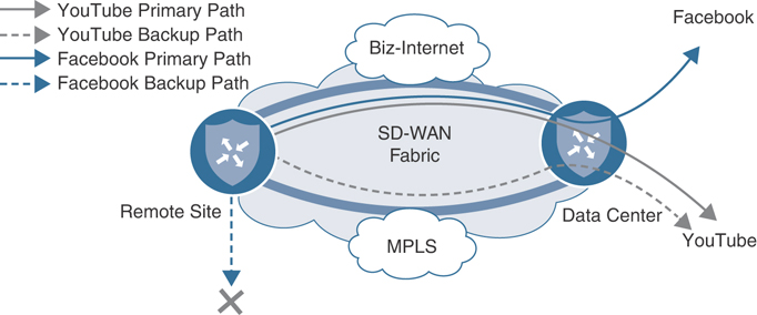
Figure 7-21 Desired Forwarding Behavior for YouTube and Facebook Applications
Before the policy from Example 7-4 has been modified, the forwarding behavior as shown in Example 7-6 can be observed.
Example 7-6 Application Forwarding Behavior Without Policy Changes
!
! Before modifications are made to the policy, both YouTube and Facebook traffic is
! forwarded across both links.
!
BR2-vEdge-1# show policy service-path vpn 1 interface ge0/3 source-ip 10.1.102.1
 dest-ip 0.0.0.0 protocol 1 app youtube all
Number of possible next hops: 2
Next Hop: IPsec
  Source: 172.16.102.2 12346 Destination: 172.16.21.2 12366 Color: mpls
Next Hop: IPsec
  Source: 100.64.102.2 12346 Destination: 100.64.21.2 12386 Color: biz-internet

BR2-vEdge-1# show policy service-path vpn 1 interface ge0/3 source-ip 10.1.102.1
 dest-ip 0.0.0.0 protocol 1 app facebook all
Number of possible next hops: 2
Next Hop: IPsec
  Source: 172.16.102.2 12346 Destination: 172.16.21.2 12366 Color: mpls
Next Hop: IPsec
  Source: 100.64.102.2 12346 Destination: 100.64.21.2 12386 Color: biz-internet

BR2-vEdge-1#
Example 7-6 again uses the show policy service-path command to be able to determine the path or paths that particular flows would take through a WAN Edge router. This example shows the outputs for the application “youtube” and the application “facebook,” indicating 255that flows from both applications would be load-shared across both the MPLS and Biz-Internet tunnels to DC2-vEdge1. In order to change this behavior, the policy configured in Example 7-7 will use the local-tloc action and the tloc-list action.
The local-tloc action is configured with the syntax
set local-tloc color {color} [encap {ipsec|gre}]
where color is any one of the supported TLOC colors. This action directs packets to be forwarded out of the TLOC that is specified in the color argument. If this TLOC is not available (because it is not configured, the tunnel is down, or so on), then the traffic is forwarded out any valid TLOC, as indicated by the routing table. There is also a configuration command called set local-tloc-list that allows for the selection of one or more colors. vManage defaults to using this syntax when policies are configured through the vManage GUI.
The tloc-list action in a centralized data policy is similar in structure and function to the centralized control policy tloc-list action that was explored in Use Case 2. By using the TLOC-List action, a network administrator is statically specifying the fabric tunnel endpoints toward which the flow will be forwarded. This functionality is roughly equivalent to the set next-hop-address functionality in a traditional policy-based-routing route-map. With the TLOC-List action, if the TLOCs specified in the list are not available, then the traffic is blackholed, even though there may be a different path available.
In short, the local-tloc action selects the preferred egress TLOC on the local WAN Edge router, while the TLOC-List action mandates the TLOCs on the receiving WAN Edge that the traffic will be forwarded to. The modified policy in Example 7-7 shows these two different configurations.
Example 7-7 Application-Based Traffic Engineering Policy
policy
 ! <<<No changes were made to the control policies, VPN membership policies, or
 ! the Guest VPN data policies, and they are omitted for brevity.>>>
 !
data-policy _CorporateVPN_Branch_-1763799758
  vpn-list CorporateVPN
    sequence 1
     match
      app-list TRUSTED_APPS
      source-ip 0.0.0.0/0
     !
     action accept
      nat use-vpn
      nat fallback
      count CORP_DCA_359403425
     !
    !
    !
    ! Sequence 11 uses the local-tloc-list command to indicate the color or colors
    ! on the local WAN Edge that are PREFERRED to be used for forwarding this flow.
    !
    sequence 11
     match
      app-list YouTube
      source-ip 0.0.0.0/0
     !
     action accept
      count CORP_YOUTUBE_359403425
      set
      local-tloc-list
       color biz-internet
       encap ipsec
      !
     !
    !
    !
    ! Sequence 21 uses the tloc-list command to specify the TLOCs that this traffic
    ! MUST be forwarded to. If the TLOCs are unavailable, the traffic will be
    ! dropped.
    !
    sequence 21
     match
      app-list Facebook
      source-ip 0.0.0.0/0
     !
     action accept
      count CORP_FACEBOOK_359403425
     set
       vpn 1
      tloc-list Europe_DC_INET_TLOCS
      !
     !
    !
  default-action accept
 !
  vpn-list GUEST_ACCESS_VPN
  ! <<<Omitted for brevity>>>
 !
 lists
 ! <<<Some lists without changes are omitted for brevity>>>
 !
  app-list Facebook
   app facebook
   app facebook_messenger
   app fbcdn
   app facebook_mail
   app facebook_live
  !
  app-list YouTube
   app youtube
   app youtube_hd
  !
  site-list BranchOffices
   site-id 100-199
  !
  tloc-list Europe_DC_INET_TLOCS
   tloc 10.0.20.1 color biz-internet encap ipsec preference 500
   tloc 10.0.20.2 color biz-internet encap ipsec preference 400
  !
 !
!
apply-policy
 site-list Europe_Branches
  control-policy Euro_Reg_Mesh_with_FW_MultiTopo out
 !
 site-list BranchOffices
  data-policy _CorporateVPN_Branch_-1763799758 from-service
  control-policy Branch_Extranet_Route_Leaking in
  vpn-membership vpnMembership_373293275
 !
 site-list DCs
  control-policy DC_Inbound_Control_Policy in
 !
 site-list North_America_Branches
  control-policy North_America_Reg_Mesh_with_FW out
 !
!
In sequence 11 in Example 7-7, YouTube application traffic is being matched and then the local-tloc-list action is configured to forward this traffic out of the Biz-Internet TLOC, if the TLOC is available. In sequence 21, Facebook traffic is being matched and is being forwarded to Biz-Internet TLOCs on DC2-vEdge1 and DC2-vEdge2, as specified with the tloc-list action. The effects of these two different configuration options can be seen in Example 7-8, where the results are shown in both a steady state and a state where an Internet connection of DC2 has failed.
Example 7-8 Application Traffic Engineering Behavior with Policy in Steady State and Failed State
!
! When all of the Biz-Internet BFD Sessions to Site 20 are operational:
!
BR2-vEdge-1# show bfd sessions remote-color biz-internet site-id 20
                                      SOURCE TLOC      REMOTE TLOC
                        DST PUBLIC                      DST PUBLIC         DETEC
T      TX
SYSTEM IP        SITE ID  STATE       COLOR            COLOR            SOURCE I
P                       IP                              PORT        ENCAP  MULTI
PLIER  INTERVAL(msec) UPTIME          TRANSITIONS
--------------------------------------------------------------------------------
--------------------------------------------------------------------------------
---------------------------------------------
10.0.20.1        20       up          biz-internet     biz-internet     100.64.1
02.2                    100.64.21.2                     12386       ipsec  7
       1000           0:00:24:25      6
10.0.20.2        20       up          biz-internet     biz-internet     100.64.1
02.2                    100.64.22.2                     12386       ipsec  7
       1000           0:00:24:25      5
10.0.20.1        20       up          lte              biz-internet     100.127.
102.2                   100.64.21.2                     12386       ipsec  7
       1000           0:03:07:26      1
10.0.20.2        20       up          lte              biz-internet     100.127.
102.2                   100.64.22.2                     12386       ipsec  7
       1000           0:00:47:23      1
!
! In steady state, when all of the links are operational, the two configurations
! have the same effect:  Traffic matching the YouTube app-list and traffic matching
! the Facebook app-list are both forwarded across biz-internet tunnel to
! 100.64.21.2 (DC2-vEdge1).
BR2-vEdge-1# show policy service-path vpn 1 interface ge0/3 source-ip 10.1.102.1
 dest-ip 0.0.0.0 protocol 1 app youtube all
!
Number of possible next hops: 1
Next Hop: IPsec
  Source: 100.64.102.2 12346 Destination: 100.64.21.2 12386 Color: biz-internet

BR2-vEdge-1# show policy service-path vpn 1 interface ge0/3 source-ip 10.1.102.1
 dest-ip 0.0.0.0 protocol 1 app facebook all
Number of possible next hops: 1
Next Hop: IPsec
  Source: 100.64.102.2 12346 Destination: 100.64.21.2 12386 Color: biz-internet

!
! After an internet failure at DC2, all of the Biz-Internet BFD Sessions to
! Site 20 are down:
!
BR2-vEdge-1# show bfd sessions remote-color biz-internet site-id 20
                                      SOURCE TLOC      REMOTE TLOC
        DST PUBLIC                      DST PUBLIC         DETECT      TX
SYSTEM IP        SITE ID  STATE       COLOR            COLOR            SOURCE IP
        IP                              PORT        ENCAP  MULTIPLIER  INTERVAL(msec) UPTIME
      TRANSITIONS
------------------------------------------------------------------------------------------------
------------------------------------------------------------------------------------------------
-------------
10.0.20.1        20       down        biz-internet     biz-internet     100.64.102.2
        100.64.21.2                     12386       ipsec  7           1000           NA
      11
10.0.20.2        20       down        biz-internet     biz-internet     100.64.102.2
        100.64.22.2                     12386       ipsec  7           1000           NA
      10
10.0.20.1        20       down        lte              biz-internet     100.127.102.2
        100.64.21.2                     12386       ipsec  7           1000           NA
      4
10.0.20.2        20       down        lte              biz-internet     100.127.102.2
       100.64.22.2                     12386       ipsec  7           1000           NA
      4
!
! In a failed state, where there is no longer a path to DC2 via the Biz-Internet color,
! the YouTube traffic will be forwarded across the MPLS path.
!
BR2-vEdge-1# show policy service-path vpn 1 interface ge0/3 source-ip 10.1.102.1
 dest-ip 0.0.0.0 protocol 1 app youtube all
Number of possible next hops: 1
Next Hop: IPsec
  Source: 172.16.102.2 12346 Destination: 172.16.21.2 12366 Color: mpls
!
! The Facebook application, will not failover to the MPLS path. The tloc-list
! action statically specifies the next-hop tunnel endpoints.  If those
! endpoints are not available, the traffic is blackholed.
!
BR2-vEdge-1# show policy service-path vpn 1 interface ge0/3 source-ip 10.1.102.1
 dest-ip 0.0.0.0 protocol 1 app facebook all
Number of possible next hops: 1
Next Hop: Blackhole
BR2-vEdge-1#
When the network is in a state where all of the Biz-Internet tunnels are operating as expected, Example 7-8 shows that the forwarding behavior for these two configurations is the same: both the YouTube and Facebook flows are forwarded across the Biz-Internet tunnel to 100.64.21.2, the interface IP address of DC2-vEdge1. The difference between these two configurations comes when the network is in a failed state, such as would occur if the Biz-Internet transport to Datacenter 2 was severed by a fiber-seeking backhoe. Example 7-8 shows that the YouTube application, configured with the local-tloc-list action, fails over to the MPLS TLOC and continues to operate. The Facebook application, on the other hand, which was configured with the tloc-list action where the next hops were statically specified, does not failover, and the traffic is instead blackholed.
Use Case 12 Review
This use case again illustrates that there are often several different design and configuration choices that can be used to accomplish any specific task. It is important for administrators to consider not only the forwarding behavior that is desired, but also to think through the possible outcomes and effects of different failure scenarios, and the effects of design choices on the eventual outcomes. As Example 7-8 shows, TLOC lists are a powerful but unforgiving tool; use them with caution.
This example used Facebook and YouTube as two sample applications for illustration purposes, but these placeholders can easily be replaced with applications that are important to the business: thin clients, enterprise resource planning (ERP) systems, file servers, email, collaboration software, and so on. Network administrators can apply the lessons here to solve the challenges facing their organizations.
Use Case 13: Protecting Corporate Users with a Cloud-Delivered Firewall
Throughout the course of this chapter, we have explored use cases where users were accessing the Internet by egressing directly from the WAN Edge, such as the WebEx application in Use Case 11. In Use Case 12, there were examples of traffic engineering policies that allowed users to access Internet-based applications by backhauling the traffic through a data center. Use Case 13 will explore a third option: integrating a cloud-delivered firewall (CDFW), such as Cisco Umbrella Secure Internet Gateway (SIG), into the SD-WAN fabric, and redirecting traffic flows to Umbrella SIG with service insertion policies. This use case is going to focus on the integration of Umbrella SIG with the SD-WAN fabric and the centralized data policies that are necessary in order to redirect traffic to Umbrella SIG. More information about Cisco Umbrella SIG, and the specific configurations for integrating Umbrella with Cisco SD-WAN, can be found at the end of this chapter and at http://cisco.com/go/umbrella.
In Chapter 6, a firewall inside one of the sites was configured and advertised as a service in the SD-WAN fabric. All of the traffic that was passing between sites was forwarded through the service based on manipulating the routing table with a centralized control policy. In this use case, rather than manipulating the routing table to send all traffic through the CDFW, a centralized data policy will be created to only send a specific set of applications through the firewall—specifically, a variety of Google apps. Figure 7-22 illustrates this traffic flow.
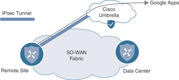
Figure 7-22 Redirecting Google Apps Traffic to the Cisco Umbrella Secure Internet Gateway
The first step in this use case will be configuring the connectivity to the CDFW. Next, we’ll configure the CDFW as a service in the SD-WAN fabric, as shown in Example 7-9. While this example uses Cisco Umbrella, this integration would also work with most any other CDFW provider that can use IPsec or GRE tunnels to establish connectivity.
Example 7-9 Local Configuration with CDFW Tunnel
!
! An IPSec tunnel to Cisco Umbrella is configured in VPN0.
!
BR2-vEdge-1# show running-config vpn 0 interface ipsec1
vpn 0
 interface ipsec1
  ip address 10.255.255.253/30
  tunnel-source-interface ge0/0
  tunnel-destination      146.112.82.8
  ike
   version      2
   rekey        28800
   cipher-suite aes256-cbc-sha1
   group        14
   authentication-type
    pre-shared-key
     pre-shared-secret abcdegfhijklmnopqrstuvwxyz
     local-id          SDWAN_BOOK@XXXXXXX-XXXXXXXXX-umbrella.com
     remote-id         146.112.82.8
    !
   !
  !
  ipsec
   rekey                   3600
   replay-window           512
   cipher-suite            aes256-gcm
   perfect-forward-secrecy none
  !
  no shutdown
 !
!
! The IPSec tunnel is in the Up / Up state
!
BR2-vEdge-1# show interface ipsec1
                                         IF      IF      IF
                AF                       ADMIN   OPER    TRACKER
VPN  INTERFACE  TYPE  IP ADDRESS         STATUS  STATUS  STATUS   DESC
------------------------------------------------------------------------
0    ipsec1     ipv4  10.255.255.253/30  Up      Up      NA       -

!
! A service is defined in VPN1 that references the new ipsec tunnel in VPN 0
!
BR2-vEdge-1# show running-config vpn 1
vpn 1
service IDP interface ipsec1
 interface ge0/3
  ip address 10.1.102.1/30
  no shutdown
 !
 ip route 10.1.102.64/26 10.1.102.2
BR2-vEdge-1#
The first step in the process is to establish the tunnel for connectivity to the CDFW solution, as shown in Example 7-9. The details for establishing these tunnels are typically provided by the CDFW vendor. The documentation for configuring a tunnel with Cisco Umbrella SIG can be found here: https://docs.umbrella.com/umbrella-user-guide/docs/add-a-tunnel-viptela. After the tunnel interface is configured, the next step is to configure a network service with the service command under the service-side VPN. This configuration is very similar to the service that was configured in Chapter 6. In this case, a service type of IDP (for Intrusion Detection and Prevention) was selected. After the service is configured, a centralized data policy needs to be created to redirect the traffic of interest to the network service.
Centralized control policies are enforced centrally on the vSmarts and are only evaluated when sending or receiving control plane updates with the Overlay Management Protocol. As such, there is limited impact from the control policies on the vSmarts and no performance impact on the WAN Edge routers. Centralized data policies, however, are forwarded to the WAN Edges from the vSmarts, where each flow is then evaluated against the policy. Hence, there can be significant performance implications to the structure of the policy. It is beneficial to structure the policies in a way that as few of the sequences as necessary are evaluated for each flow. For example, if you have a data policy that is only concerned with external applications, then create the first sequence of the data policy to match all of the internal traffic and eliminate it from consideration of the rest of the sequences in the policy (rather than relying on the default action at the end of the data policy).
While not strictly necessary for this policy in a lab environment, this best practice has been implemented in the policy in Example 7-10 by the first sequence in the policy.
Example 7-10 SIG Policy
policy
 ! <<<No changes were made to the control policies, VPN membership policies, or
 ! the Guest VPN data policies, and they are omitted for brevity.>>>
 !
 data-policy _CorporateVPN_Branch__1930818813
  vpn-list CorporateVPN
    !
    ! Sequence 1 stops any traffic that is being routed across the fabric from
    ! needing to be processed by any of the rules that are for internet bound
    ! applications.
    !
    sequence 1
     match
      destination-data-prefix-list INTERNAL_ADDRESSES
     !
     action accept
      count INTERNAL_PCKTS_1041684049
     !
    !
    sequence 11
     match
      app-list TRUSTED_APPS
      source-ip 0.0.0.0/0
     !
     action accept
      nat use-vpn 0
      nat fallback
      count CORP_DCA_1041684049
     !
    !
    sequence 21
     match
      app-list YouTube
      source-ip 0.0.0.0/0
     !
     action accept
      count CORP_YOUTUBE_1041684049
      set
       local-tloc-list
        color biz-internet
        encap ipsec
      !
     !
    !
    sequence 31
     match
      app-list Facebook
      source-ip 0.0.0.0/0
     !
     action accept
      count CORP_FACEBOOK_1041684049
      set
       vpn 1
       tloc-list Europe_DC_INET_TLOCS
      !
     !
    !
    !
    ! Sequence 41 redirects applications matching the “Google_Apps” list to the
    ! local instance of the IDP service. The “IDP” name matches the configured
    ! service in VPN 1.
    !
    sequence 41
     match
      app-list Google_Apps
      source-ip 0.0.0.0/0
     !
     action accept
      count UMBRELLA_PCKTS_1041684049
      set
       service  IDP local
      !
     !
    !
  default-action accept
 !
 vpn-list GUEST_ACCESS_VPN
  ! <<<Omitted for brevity>>>
 !
 lists
 ! <<<Some lists without changes are omitted for brevity>>>
 !
 !
 ! vManage includes, by default, two app-lists: one for Google_Apps, and a second for
 ! Microsoft_Apps. These two lists contain a myriad of different applications that are
 ! produced by the two organizations. Custom app-lists can be created to match
 ! only a subset of apps, but the default app-list is used in this example. The
 ! entire list is not displayed for brevity.
 !
  app-list Google_Apps
   app gmail
   app google
   app google_translate
   app gmail_drive
   app gtalk
   app youtube
   app youtube_hd
! <<< Output omitted>>>
  !
  app-list TRUSTED_APPS
   app webex-meeting
   app webex_weboffice
   app webex
  !
  app-list YouTube
   app youtube
   app youtube_hd
  !
  data-prefix-list INTERNAL_ADDRESSES
   ip-prefix 10.0.0.0/8
  !
 !
!
apply-policy
 site-list Europe_Branches
  control-policy Euro_Reg_Mesh_with_FW_MultiTopo out
 !
 site-list BranchOffices
  data-policy _CorporateVPN_Branch__1930818813 from-service
  control-policy Branch_Extranet_Route_Leaking in
  vpn-membership vpnMembership_373293275
 !
 site-list DCs
  control-policy DC_Inbound_Control_Policy in
 !
 site-list North_America_Branches
  control-policy North_America_Reg_Mesh_with_FW out
 !
!
Example 7-10 shows the changes that were made to the policy in order to accomplish the objectives of this use case. In sequence 41, packets that match the “Google_Apps” app-list are forwarded to the CDFW with the action service local command. The service local action is configured with the following syntax: set service {service} local [restrict]. This command is used to forward the traffic to one of the network services that is locally present on the WAN Edge, such as what was configured in VPN 1 in Example 7-9. The service value can be any one of the seven supported network services: FW, IPS, IDP, netsvc1, netsvc2, netsvc3, or netsvc4. The optional [restrict] value specifies that if the local service is unavailable, the traffic should be dropped.
With the policy changes in Example 7-10 applied to the network, you will see the results in Example 7-11.
Example 7-11 Validating Service Insertion Policy with CDFW
BR2-vEdge-1# show policy data-policy-filter data-policy-vpnlist CorporateVPN
data-policy-filter _CorporateVPN_Branch__1930818813
 data-policy-vpnlist CorporateVPN
  data-policy-counter CORP_DCA_-240945300
   packets 1
   bytes   96
  data-policy-counter CORP_YOUTUBE_-240945300
   packets 1
   bytes   96
  data-policy-counter CORP_FACEBOOK_-240945300
   packets 141
   bytes   13737
  data-policy-counter INTERNAL_PCKTS_-240945300
   packets 47
   bytes   11748
!
! The counters indicate that traffic is being forwarded to the Cisco Umbrella SIG.
!
  data-policy-counter UMBRELLA_PCKTS_-240945300
   packets 272
   bytes   43518
BR2-vEdge-1#
!
! The “show policy service-path” output for “google” and “gmail”, two different!
  services that are covered by the app-list “Google_Apps”, are being forwarded
! out of the IPSec tunnel that connects to the Umbrella SIG.
!
BR2-vEdge-1# show policy service-path vpn 1 interface ge0/3 source-ip 10.1.102.1
 dest-ip 0.0.0.0 protocol 1 app google
Next Hop: RFC-IPsec

BR2-vEdge-1# show policy service-path vpn 1 interface ge0/3 source-ip 10.1.102.1
 dest-ip 0.0.0.0 protocol 1 app gmail
Next Hop: RFC-IPsec
!
! However, the “show policy service-path” output for “youtube,” which is also
! covered by the app-list “Google_Apps”, is being forwarded to DC2-vEdge1
! instead of Umbrella SIG.
!
BR2-vEdge-1# show policy service-path vpn 1 interface ge0/3 source-ip 10.1.102.1
 dest-ip 0.0.0.0 protocol 1 app youtube
Next Hop: IPsec
  Source: 100.64.102.2 12346 Destination: 100.64.21.2 12386 Color: biz-internet
!
! The “show policy from-vsmart lists app-list” output confirms that the app
! “youtube” is part of two different app-lists: “Google_Apps” and “YouTube”.
!
BR2-vEdge-1# show policy from-vsmart lists app-list | i Google\|You\|you
from-vsmart lists app-list Google_Apps
 app youtube
 app youtube_hd
from-vsmart lists app-list YouTube
 app youtube
 app youtube_hd
BR2-vEdge-1#
!
! The “show policy from-vsmart” output indicates why “youtube” is being routed
! differently than “google” and “gmail”. The app-list “YouTube” is being matched
! in sequence 11, and has the action “local-tloc-list” applied to it. The
! rest of the sequences are therefore not evaluated for “youtube” traffic. Since
! Cisco SD-WAN policies use a first-match logic, the actions in sequence 41 are
! never applied to “youtube” traffic.
!
BR2-vEdge-1# show policy from-vsmart data-policy vpn-list CorporateVPN seq 11,41

from-vsmart data-policy _CorporateVPN_Branch__1930818813
 vpn-list CorporateVPN
  sequence 11
   match
    source-ip 0.0.0.0/0
    app-list  YouTube
   action accept
    count CORP_YOUTUBE_-240945300
    set
     local-tloc-list
      color biz-internet
      encap ipsec
  sequence 41
   match
    source-ip 0.0.0.0/0
    app-list  Google_Apps
   action accept
    count UMBRELLA_PCKTS_-240945300
    set
     service IDP
     service local
BR2-vEdge-1#
Example 7-11 shows that both the show policy data-policy-filter counters and show policy service-path can be used to validate that the service insertion policy is successfully redirecting traffic to the Cisco Umbrella SIG service. This example also highlights potential challenges that network administrators may encounter when configuring centralized data policies. In this policy, the application “youtube” was matched by the criteria in both sequence 11 and in sequence 41. Since the sequences are evaluated ordinally, when the application flows were matched by sequence 11, the actions for sequence 11 were performed and no further sequences were evaluated. This resulted in the “youtube” traffic being forwarded across the Biz-Internet tunnel, rather than being redirected with the service insertion action to the CDFW.
Use Case 13 Review
In this use case, service insertion was used to redirect specific traffic flows to Cisco Umbrella Secure Internet Gateway (SIG). Service insertion can be used for many other things than redirecting traffic to CDFWs. As Use Case 6 showed, service insertion can also be used for firewalling traffic traveling between two sites on the fabric. The uses of service insertion aren’t limited to inserting security services; other potential uses of service insertion would be redirecting traffic to WAN optimization appliances, load balancers, proxies, network sniffers, and so on.
Use Case 14: Protecting Applications from Packet Loss
In the final use case of this chapter, we will cover several tools that can be used to protect applications from the effects of lossy transport links. IP-based networks, by definition, operate at a best-effort level of packet delivery. There is no mechanism at the IP layer to ensure successful delivery of the packet, regardless of whether the underlying transport is a directly connected cable, a service such as MPLS with a contractually guaranteed SLA, or the public Internet. It is typical for all networks to experience some degree of packet loss, and most applications designed to operate on IP networks are engineered to tolerate some degree of packet loss.
One of the most effective ways to counter the effects of packet loss on the underlying transport networks is simply to move sensitive applications off of transports that are currently experiencing packet loss. In the Cisco SD-WAN fabric, this function is achieved through Application-Aware Routing policies and will be discussed in greater detail in Chapter 8. However, there are often circumstances (such as when there is only a single transport link available, or when all transport links are currently experiencing some degree of packet loss), when simply moving an application off of a lossy transport link is not a viable option. In this use case, two different tools to mitigate the effects of loss in these circumstances will be discussed: Forward Error Correction (FEC) and packet duplication.
Forward Error Correction for Audio and Video
The first technology we are going to examine is Forward Error Correction (FEC). FEC is not a new or novel technology, as different methods have been used with different implementations for decades. The principle behind FEC is that additional information (parity) is transmitted along with the original message such that if a portion of the original message is compromised, the entirety of the original message can be reconstructed. There are many protocols in common use that implement some form of FEC at different layers of the networking stack: 40GBASE-T and 100GE Ethernet standards use FEC at Layer 2, and most Voice over IP (VoIP) protocols implement some form of FEC at Layer 7. With Cisco SD-WAN, we now also have the ability to add FEC to the network layer.
Figure 7-23 shows the current state of the MPLS transport network on BR2-vEdge1. The Monitor > Network > WAN Tunnel output indicates that the MPLS network is currently experiencing 4–6% packet loss. In this use case, we will implement FEC in order to mitigate the impact of this lossy transport network on the audio and video applications that the employees are using to collaborate with.
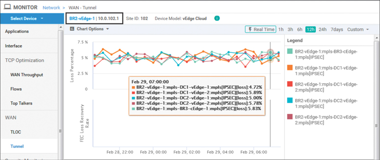
Figure 7-23 Monitor > Network > WAN Tunnel Shows the Current Packet Loss Rates
With Cisco SD-WAN, FEC operates on sets of four packets called an FEC block, as illustrated in Figure 7-24. In the first step, the four packets in an FEC block are processed with a mathematical operation called XOR. The result of this operation is transmitted in the fifth packet, called a parity packet. Each of the packets is encoded with a new FEC header and transmitted to the receiver. If any one of the original four packets is lost in transit to the receiver, as indicated in Step 2, but the parity packet is received with the three remaining original packets, the XOR operation is reversed such that the lost packet can be reconstructed from the three that were received and the parity information that is stored in the fifth packet, as indicated in Step 3. If two or more of the five transmitted packets (four data and one parity) are corrupted or lost, the lost packets cannot be reconstructed, and only the correctly received packets will be forwarded on to the end host. In this circumstance, the end hosts will notice that packet loss has occurred.
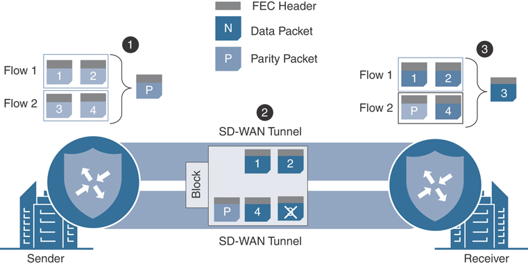
Figure 7-24 FEC Illustration
The process of sending five packets (four data packets and one parity packet) for every four packets worth of data being transmitted across the WAN would result in an increase of bandwidth consumption of at least 25% (the parity packet is as large as the largest data packet out of the set of four in the FEC block). While this increase in bandwidth consumption can be beneficial during times of packet loss on the transport links, it may also be unnecessary during a large portion of the time. In order to optimize this, there are two different FEC configuration modes: FEC-always and FEC-adaptive. FEC-always operates exactly as it sounds: the FEC process takes place unconditionally. FEC-adaptive, on the other hand, only operates when the loss percentage on the transport link is detected to be more than 2%. As of 19.2 code, this 2% value is static and is not configurable.
In order to implement this packet loss minimization policy, we will need a new sequence to match on the audio/video application family. Then, we need to enable FEC-adaptive in order to provide FEC when the transport packet losses are above 2%. In addition to configuring this on the data policy that is applied to the branch routers, a corresponding policy will need to be configured on the data center routers so that the traffic that is being forwarded from the data center to the branch sites is also protected by FEC. This policy also configures the local-tloc action in order to pin the traffic to the MPLS transport to better illustrate what is happening with the FEC policy. Example 7-12 shows these configurations.
Example 7-12 FEC Policy
policy
 ! <<<No changes were made to the control policies, VPN membership policies, or
 ! the Guest VPN data policies, and they are omitted for brevity.>>>
 !
 ! Branch Data Policy
 !
data-policy _CorporateVPN_Branch__1623113498
  vpn-list CorporateVPN
  ! Sequence 1 matches all of the applications in the Audio / Video App family
  ! and turns on fec-adaptive.
  !
    sequence 1
     match
      app-list AUDIO_VIDEO_APPS
      source-ip 0.0.0.0/0
     !
     action accept
      count CORP_AUDIO_VIDEO_-548650615
      loss-protect fec-adaptive
     loss-protection forward-error-correction adaptive
      set
       local-tloc-list
        color mpls
      !
     !
    !
    sequence 11
     match
      destination-data-prefix-list INTERNAL_ADDRESSES
     !
     action accept
      count INTERNAL_PCKTS_-548650615
     !
    !
    !<<<<remaining sequences are unchanged and omitted for brevity>>>>
    !
 default-action accept
 !
  vpn-list GUEST_ACCESS_VPN
  ! <<<Omitted for brevity>>>
 !
 ! A corresponding policy is also configured on the datacenter routers in order
 ! to apply the FEC policy to traffic that is being sent from the DC to the Branch
 !
 data-policy _CorporateVPN_DC_Corp__443359352
  vpn-list CorporateVPN
    sequence 1
     match
      app-list AUDIO_VIDEO_APPS
      source-ip 0.0.0.0/0
     !
     action accept
      count CORP_AUDIO_VIDEO_-1728404761
     loss-protect fec-adaptive
     loss-protection forward-error-correction adaptive
      set
       local-tloc-list
        color mpls
      !
     !
    !
  default-action accept
 !
 lists
 ! <<<Some lists without changes are omitted for brevity>>>
 !
  app-list AUDIO_VIDEO_APPS
   app-family audio-video
   app-family audio_video
  !
  !
 !
!
apply-policy
 site-list Europe_Branches
  control-policy Euro_Reg_Mesh_with_FW_MultiTopo out
 !
 site-list BranchOffices
  data-policy _CorporateVPN_Branch__1623113498 from-service
  control-policy Branch_Extranet_Route_Leaking in
 vpn-membership vpnMembership_373293275
 !
 site-list DCs
 data-policy _CorporateVPN_DC_Corp__443359352 from-service
  control-policy DC_Inbound_Control_Policy in
 !
 site-list North_America_Branches
  control-policy North_America_Reg_Mesh_with_FW out
 !
!
Example 7-12 includes the new sequence that was added into the data policy for the branch sites as well as the new policy that was created and applied to the data center sites. The effects of this policy can be seen with the show tunnel statistics fec command, as shown in Example 7-13.
Example 7-13 Validating FEC Policy from the Command Line
DC2-vEdge-1# show tunnel statistics fec dest-ip 172.16.102.2
tunnel stats ipsec 172.16.21.2 172.16.102.2 12366 12346
 fec-rx-data-pkts     60308
 fec-rx-parity-pkts   15095
 fec-tx-data-pkts     759660
 fec-tx-parity-pkts   189915
 fec-reconstruct-pkts 1100
 fec-capable          true
 fec-dynamic          true
DC2-vEdge-1#
Example 7-13 shows the output from DC2-vEdge-1, the recipient of the flows from BR2-vEdge1. The fec-rx-data-pkts and fec-rx-parity-pkts values are the number of data packets and parity packets, respectively, that have been received by this router. Allowing for slight discrepancies, due to the packets that may have been lost in transit, it is notable that the approximately 60,000 received data packets are approximately four times the 15,000 received parity packets. This is as would be expected since there are four data packets and a single parity packet in each FEC block. The fec-reconstruct-pkts value specifies how many packets were able to be recovered based on the received parity packets. This indicates that there were 1,100 times where at least three, but not four, of the data packets in the FEC block were received by DC2-vEdge-1. Using the received parity packet, the router was able to reconstruct the missing packets for these blocks, and the end hosts were unaware that any packet loss occurred during the transmission. The ratio of FEC blocks that were able to be reconstructed versus the total number of missing packets is graphed as the FEC Loss Recovery Rate in Figure 7-25. The fec-tx-data-pkts and fec-tx-parity-pkts values specify how many data packets and parity packets, respectively, have been sent to BR2-vEdge1.
Packet Duplication for Credit Card Transactions
As Figure 7-25 indicates, while FEC can be effective at dramatically reducing the number of packets that are lost by the end applications, even in the preceding example, there are many times when the Loss Recovery Rate is not 100%. For those circumstances where the utmost effort needs to be made to have zero packet loss, packet duplication may be the appropriate solution.
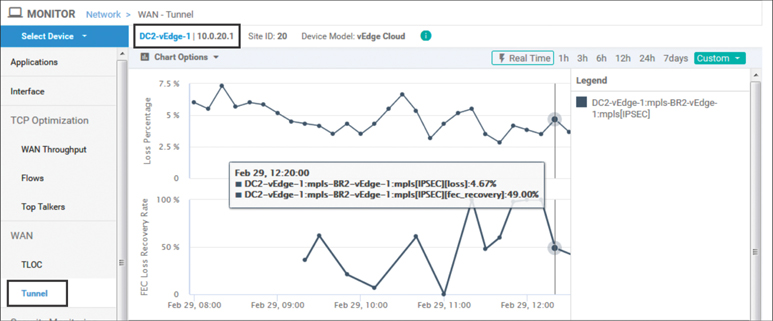
Figure 7-25 The Current Packet Loss Rates and FEC Recovery Rates
Figure 7-26 illustrates WAN Edges forwarding traffic flows with a packet duplication policy enabled. For each packet that is forwarded across a tunnel, a duplicate packet is forwarded across a different tunnel between the same pair of WAN Edge routers. The tunnel that is selected to forward the duplicate packet is the tunnel that currently has the lowest rate of packet loss of any of the tunnels between the pair of WAN Edges (excluding the tunnel that was used to forward the original packet).
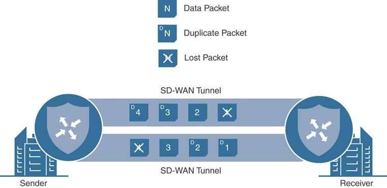
Figure 7-26 Packet Duplication Illustration
This type of policy is commonly used in retail environments and applied to credit card transactions. Credit card transactions are typically very small flows, but if a packet is lost in transit and is required to be retransmitted, the end-user experience can be slowed down dramatically. For this reason, network administrators find that it may be worth the “price” of transmitting every packet twice in order to ensure that the latency penalty caused by a packet needing to be retransmitted can be avoided.
Example 7-14 demonstrates the forwarding conditions between the credit card reader in branch 2 and the payment server in the data center through the use of Internet Control Message Protocol (ICMP). The current path between these two sites is experiencing more than 3% packet loss.
Example 7-14 Packet Loss on PCI Segment Resulting in Slow Credit Card Processing
test@BR2-PCI:~$ sudo ping 10.2.10.100 -i .001 -c 10000 -q
PING 10.2.10.100 (10.2.10.100) 56(84) bytes of data.

--- 10.2.10.100 ping statistics ---
10000 packets transmitted, 9612 received, 3% packet loss, time 50580ms
rtt min/avg/max/mdev = 2.398/4.804/104.705/2.810 ms, pipe 9
test@BR2-PCI:~$
Example 7-15 shows the data policies that are configured on the PCI VPNs in order to perform packet duplication and protect this loss-sensitive traffic. Note that two sequences are configured in both the policy applied to the data center and the policy applied to the branches. One sequence matches traffic with a source address of the payment servers; the other sequence matches the return traffic (traffic with a destination address of the payment servers). Structuring the policy this way enables the policy to be used for both the data center and branch locations simultaneously.
Example 7-15 Packet Duplication Policy
policy
 ! <<<No changes were made to the control policies, VPN membership policies,
 ! the Guest VPN or the Corporate VPN data policies, and they are omitted for
 ! brevity.>>>
 !
 data-policy _CorporateVPN_Branch_-1923459860
  vpn-list CorporateVPN
  !  <<<Omitted for brevity>>>
  !
  vpn-list PCI_VPN
    sequence 1
     match
      source-data-prefix-list PAYMENT_SERVERS
     !
     action accept
      count PCI_PCKTS_-1949123913
      set
       local-tloc-list
        color mpls
      !
     loss-protect pkt-dup
     loss-protection packet-duplication
     !
    !
    sequence 11
     match
      destination-data-prefix-list PAYMENT_SERVERS
     !
     action accept
      count PCI_PCKTS_-1949123913
      set
       local-tloc-list
        color mpls
      !
     loss-protect pkt-dup
     loss-protection packet-duplication
     !
    !
  default-action accept
 !
  vpn-list GUEST_ACCESS_VPN
  !  <<<Omitted for brevity>>>
 !
 data-policy _CorporateVPN_DC_Corp_1741652260
  vpn-list CorporateVPN
  !  <<<Omitted for brevity>>>
 !
  vpn-list PCI_VPN
    sequence 1
     match
      source-data-prefix-list PAYMENT_SERVERS
     !
     action accept
      count PCI_PCKTS_1715988207
      set
       local-tloc-list
        color mpls
      !
     loss-protect pkt-dup
     loss-protection packet-duplication
     !
    !
    sequence 11
     match
      destination-data-prefix-list PAYMENT_SERVERS
     !
     action accept
      count PCI_PCKTS_1715988207
      set
       local-tloc-list
        color mpls
      !
     loss-protect pkt-dup
     loss-protection packet-duplication
     !
    !
  default-action accept
 !
 lists
 ! <<<Some lists without changes are omitted for brevity>>>
 !
  data-prefix-list PAYMENT_SERVERS
   ip-prefix 10.2.10.0/24
  !
  vpn-list PCI_VPN
   vpn 2
  !
 !
!
apply-policy
 site-list Europe_Branches
  control-policy Euro_Reg_Mesh_with_FW_MultiTopo out
 !
 site-list BranchOffices
  data-policy _CorporateVPN_Branch_-1923459860 from-service
  control-policy Branch_Extranet_Route_Leaking in
  vpn-membership vpnMembership_373293275
 !
 site-list DCs
  data-policy _CorporateVPN_DC_Corp_1741652260 from-service
  control-policy DC_Inbound_Control_Policy in
 !
 site-list North_America_Branches
  control-policy North_America_Reg_Mesh_with_FW out
 !
!
After the policy in Example 7-15 is applied, the same test is performed again on the credit card reader as was performed in Example 7-14. As Example 7-16 shows, the packet loss has been completely eliminated from the perspective of the end hosts.
Example 7-16 Results after Packet Duplication Applied to the Network
test@BR2-PCI:~$ sudo ping 10.2.10.100 -i .001 -c 10000 -q
PING 10.2.10.100 (10.2.10.100) 56(84) bytes of data.

--- 10.2.10.100 ping statistics ---
10000 packets transmitted, 10000 received, 0% packet loss, time 45476ms
rtt min/avg/max/mdev = 2.385/4.512/53.553/1.963 ms, pipe 11
test@BR2-PCI:~$
Using the Tunnel Packet Duplication Statistics output from the Real Time display on DC1-vEdge1, Figure 7-27 shows in the PKTDUP RX column that only 9,800 of the original 10,000 packets were received on the MPLS tunnel. However, because all 10,000 duplicated packets were received on the Internet tunnel, as indicated by the 10,000 output in the PKTDUP RX OTHER column, the value in the PKTDUP RX THIS column is 10,000. The PKTDUP RX THIS column reflects the total number of original packets that the WAN Edge was able to receive from a combination of the primary tunnel and the tunnel forwarding the duplicate packets.
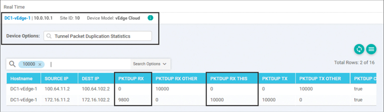
Figure 7-27 Real-Time Output Indicating the Packet Duplication Statistics on DC1-vEdge1
Output in PKTDUP TX and PKTDUP TX OTHER of Figure 7-27 indicate that the 10,000 reply packets were also transmitted down the MPLS tunnel and duplicated down the Biz-Internet tunnel. It is a good thing that the packets were duplicated, because according to the output in Figure 7-28, only 9,812 of the original 10,000 packets were received on the MPLS path. Just as with the DC1-vEdge1 router, the 10,000 value in PKTDUP RX THIS, which represents the number of original packets received across any transport tunnel and ready to be forwarded to the local end hosts, indicates that no packets were lost in transit for which a duplicate did not successfully arrive.

Figure 7-28 Real-Time Output Indicating the Packet Duplication Statistics on BR2-vEdge1
Use Case 14 makes extensive use of two different data plane features that are designed to protect against packet loss: packet duplication and Forward Error Correction. There is a third feature, TCP optimization (TCP-Opt), that also fundamentally alters data packets as they are forwarded through the router. All three of these features make fundamental changes to the typical forwarding operations and go well beyond the earlier use cases where a packet was being redirected or remarked.
Unfortunately, the implementations of these three features—Forward Error Correction, packet duplication, and TCP optimization—are different between the Viptela OS–based platforms and the XE-SDWAN-based platforms. While all three features are supported on both platforms, it is not possible in current software (Viptela 19.2 / XE 16.12) to interoperate between the two platform families when using these three features. Network administrators will need to keep this in mind when planning and designing their deployments, and always check the release notes for the latest information about which features are supported on which platforms.
Use Case 14 Review
In this use case, we explored two different methods for reducing the impact of lossy underlying transport networks on business applications: Forward Error Correction and packet duplication. In Chapter 8, another method, Application-Aware Routing, will be discussed in great detail. Application-Aware Routing can also be used to solve similar challenges by moving affected traffic classes off of transports that are currently exhibiting packet loss.
The full and complete policy for all of the configuration that has been performed in Chapters 6 and 7 can be found in Appendix B.
Summary
This chapter discussed one of the key types of SD-WAN policies: centralized data policies. Several different use cases using centralized data policies were reviewed, including how centralized data policies can be used to make per-application forwarding decisions as well as for Direct Cloud Access, injecting services on a per-application basis, and mitigating the effects of using lossy transport networks with Forward Error Correction and packet duplication.
The use cases reviewed in this chapter represent a large cross section of what centralized data policies can accomplish. There are a plethora of actions not included in the use cases in this chapter, however. Some additional topics that network engineers may be interested in learning more about include quality of service (specifically DSCP marking and remarking), setting the forwarding class on a flow to be matched in a Localized policy (for queuing and scheduling purposes, as covered in Chapter 9, “Local Policies”), and using traffic policers. Centralized data policies can also be used to generate Cflowd and NetFlow records that can be exported to an external flow collector for monitoring and reporting purposes. More information and configuration examples for all of these topics can be found in the Cisco documentation.
While these use cases represent some of the most common challenges that network engineers need to solve in order to meet business objectives, the tools and techniques that have been discussed throughout this chapter can also be applied and extended in novel ways to solve practically any set of requirements.
Review All Key Topics
Review the most important topics in the chapter, noted with the Key Topic icon in the outer margin of the page. Table 7-1 provides a reference for these key topics and the page numbers on which each is found.
Table 7-1 Key Topics
Key Topic Element |
Description |
Page |
|---|---|---|
Paragraph, Figure 7-1 |
Data policy directionality |
228 |
Paragraph |
Control policies vs. data policies enforced on WAN Edges via vSmarts |
241 |
Paragraph |
Concatenating data policies |
247 |
Application Traffic Engineering Behavior with Policy in Steady State and Failed State |
258 |
|
Paragraph |
Centralized control policy enforcement behaviors |
263 |
Paragraph |
Behavior of the service local command |
266 |
Paragraph |
FEC block operations |
271 |
Paragraph |
WAN Edge forwarding traffic flows with a packet duplication policy enabled |
275 |
Paragraph |
Deployment concerns for the data plane features Forward Error Correction, packet duplication, and TCP optimization |
280 |
Define Key Terms
Define the following key terms from this chapter and check your answers in the glossary:
Chapter Review Questions
1. In a centralized data policy, how do you match all flows?
Using the match-all criteria
By not specifying any matching criteria and only configuring the action statements
Only by using the default action
2. When the nat use-vpn configuration command is used, which VPN is the traffic going to be NATed into?
VPN 0
VPN 1
VPN 65535
The VPN specified in configuration
3. What is the purpose of the nat fallback configuration command?
Provides a backup forwarding path in the event that all of the WAN tunnels go down
Provides a backup forwarding path in the event that all of the local interfaces configured with NAT go down
Provides a backup forwarding path in the event that the destination is not reachable via NAT
4. In a vSmart configuration, how many data policies can applied per site?
Zero: Data policies are not applied in a vSmart configuration.
One: Each site gets one and only one data policy.
Two: Each site gets a data policy that is applied to traffic that is originating from the LAN and a second policy that is applied to the traffic that originates from the WAN.
As many as necessary, but never more than two per VPN per site.
5. When the TLOC specified in the LOCAL-TLOC action is not available, then the traffic that was matched in the data policy sequence is blackholed.
True
False
6. How many packets are in a single FEC block?
One data packet, one parity packet
One data packet, four parity packets
Two data packets, one parity packet
Four data packets, one parity packet
The value is configurable in the policy.
7. When FEC-adaptive data policies are used, what is the loss threshold at which FEC begins to operate?
0%
1%
2%
5%
The value is configurable in the policy.
8. When packet duplication is configured, which tunnel is used to send the duplicated packets?
The tunnel that is configured in the policy
The least utilized tunnel to the same destination
The same tunnel that the original packets were sent down
The tunnel that is currently experiencing the least amount of packet loss
9. When packet duplication is used, which field indicates the total number of unique packets that have been received?
PKTDUP RX
PKTDUP RX OTHER
PKTDUP RX THIS
PKTDUP TX
PKTDUP TX OTHER
10. Which of the following features are able to interoperate between Viptela OS platforms and XE-SDWAN platforms?
Forward Error Correction
Packet duplication
TCP optimization
All of these are correct.
Forward Error Correction and packet duplication
None of these answers is correct.
References
G. Jones, Ed., RFC 3871: Operational Security Requirements for Large Internet Service Provider (ISP) IP Network Infrastructure, Network Working Group, https://tools.ietf.org/html/rfc3871, September 2004
Cisco SD-WAN Command Line Reference, https://www.cisco.com/c/en/us/td/docs/routers/sdwan/command/sdwan-cr-book.html
Configuring Centralized Data Policy, https://sdwan-docs.cisco.com/Product_Documentation/Software_Features/Release_18.4/06Policy_Basics/04Centralized_Data_Policy/01Configuring_Centralized_Data_Policy
Cisco Umbrella: Add a Tunnel: Viptela, https://docs.umbrella.com/umbrella-user-guide/docs/add-a-tunnel-viptela