Chapter 11
Cisco SD-WAN Cloud onRamp
This chapter covers the following topics:
Cisco SD-WAN Cloud onRamp: This section covers what Cisco SD-WAN Cloud onRamp is and why it is relevant to your organization.
Cloud onRamp for SaaS: This section of the chapter covers the concepts and configuration of Cloud onRamp for SaaS.
Cloud onRamp for IaaS: This section of the chapter covers the concepts and configuration of Cloud onRamp for IaaS.
Cloud onRamp for Colocation: This section of the chapter covers the concepts and configuration of Cloud onRamp for colocation.
Cisco SD-WAN Cloud onRamp
In recent years, not only has the industry seen applications migrating to the cloud on a massive scale, but “born in the cloud” is becoming the de facto standard for application development and delivery. At the same time, the rapid adoption of business-critical cloud services by nearly all organizations across every vertical is fueling all things cloud and unveiling new challenges for network architects. These challenges include the following:
Providing reliable, flexible, and secure cloud connectivity models: There are a multitude of ways to reach public or private cloud workloads and applications these days. Network architects are now tasked to provide reliable and secure connectivity from the branch, hub, or data center to these workloads and applications.
Ensuring optimal cloud application performance and visibility: Since most networks have multiple egress points to the Internet, it is important to ensure the best path is utilized on a per-application basis and that performance of the path is collected and available for reporting.
Designing scalable, multi-cloud architectures: Organizations are starting to realize the benefits of a multi-cloud environment when it comes to private and public cloud workload placement. Ensuring that these architectures are scalable, easy to spin up and spin down, and stay cost-effective is key.
Cisco SD-WAN Cloud onRamp provides simple, yet highly effective workflows in vManage to optimize connectivity to Software as a Service (SaaS) applications by choosing the best-performing path in the network. Path selection is based on performance measurements obtained from all available paths. In the case where a specific path experiences degradation, the traffic is dynamically moved to a more optimal path. Cloud onRamp also automates scalable, multi-cloud connectivity to Infrastructure as a Service (IaaS) workloads by instantiating virtual SD-WAN Edge routers in a transit model and then connecting the transit network to both the SD-WAN overlay and the backend workloads. Finally, Cloud onRamp for colocation enables secure, efficient, and highly flexible service-chaining architectures to reach applications hosted in colocation facilities. Figure 11-1 shows the different types of cloud onRamp offered by Cisco SD-WAN.
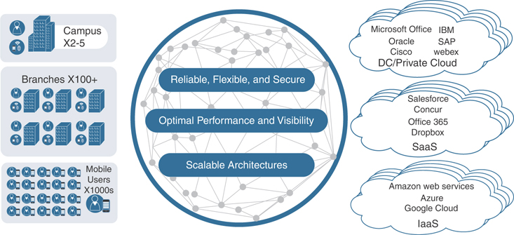
Figure 11-1 Cisco Cloud onRamp Options
Cloud onRamp for SaaS
As more applications move to the cloud, the traditional approach of backhauling traffic over expensive or low-performance WAN transports to the data center or hub for centralized Internet egress is quickly proving not to be the most optimal method for cloud application consumption. Current WAN infrastructures were never designed with cloud applications in mind: They can introduce latency and degrade the end-user experience, while the aggregation of traffic at a data center or hub often poses bottlenecks and capacity ceilings.
Network architects are tasked with reevaluating the design of their WANs to support a cloud transition, reduce network costs, and increase the visibility and manageability of their cloud traffic while ensuring an excellent user experience. Network architects are turning to inexpensive broadband Internet services to find ways to intelligently route trusted SaaS cloud-bound traffic directly from remote branches.
With Cloud onRamp for SaaS, the SD-WAN fabric continuously measures the performance of a designated SaaS application, such as Microsoft Office 365, through all available paths from a branch, including designated backhaul paths. For each path, the fabric computes a quality-of-experience score ranging from 0 to 10, with 10 being the best performance. This score gives network administrators visibility into application performance that has never before been available. Most importantly, the fabric automatically makes real-time decisions to choose the best-performing path between the end users at a remote branch and the cloud SaaS application. Enterprises have the flexibility to deploy this capability in several ways, according to their business needs and security requirements.
The benefits of Cloud onRamp for SaaS include the following:
Improved branch-office user experience for SaaS applications by using the best-performing network path
Increased SaaS application resiliency with multiple network path selections and active monitoring
Visibility into SaaS application performance by using probes that measure real-time data
Operational simplicity and consistency through centralized control and management of SaaS application policies
Figure 11-2 shows an overview of the Cloud onRamp for SaaS components.
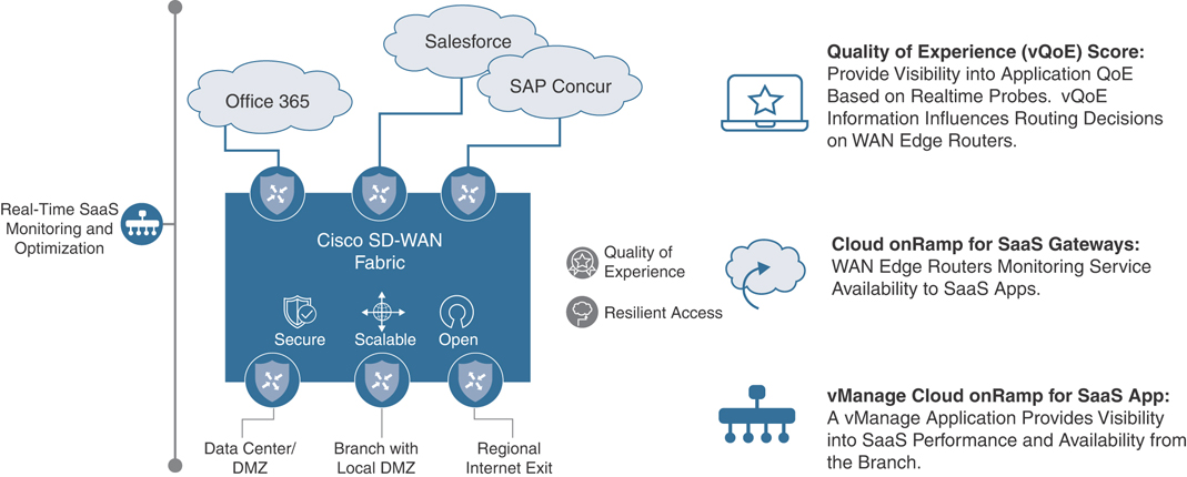
Figure 11-2 Cloud onRamp for SaaS
One common use case is direct cloud access from a remote site. Direct cloud access allows a remote site to access SaaS applications directly from the Internet. Cloud onRamp for SaaS permits only the designated application traffic to use the directly connected Internet transport securely, while all other Internet-bound traffic takes the usual path, which could be through a regional hub, a data center, or a carrier-neutral facility. This feature allows the remote site to bypass the latency of tunneling Internet-bound traffic to a central site, subsequently improving the connectivity to the prioritized SaaS application. This feature is commonly referred to as Direct Internet Access (DIA). The Cisco SD-WAN Edge router chooses the most optimal Internet path for access to these SaaS applications. Different applications could traverse different paths because the path selection is calculated on a per-application basis.
If any SaaS application path becomes unreachable or its performance score falls below an unacceptable level, the path is removed as a candidate path option. If all paths cannot be path candidates because of reachability or performance, then traffic to the SaaS application follows the normal, routed path.
Figure 11-3 illustrates a remote site using DIA to access SaaS applications.
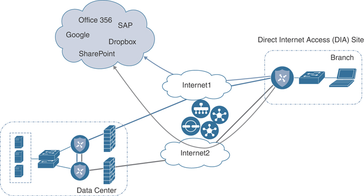
Figure 11-3 Direct Cloud Access/Direct Internet Access
Another common use case is cloud access through a gateway. Many enterprises do not use DIA at the branch office because either their sites are connected by only private transports or centralized policy or security requirements don’t permit it. They may use data centers, regional hubs, or even carrier-neutral facilities to enable Internet connectivity. In this case, SaaS traffic is tunneled to the best-performing gateway site, where it is subsequently routed to the Internet to reach the requested SaaS application service. Note that different remote sites and different applications may use different gateway sites and paths, depending on the application and measured application performance. Remote sites that use gateway sites for Internet access are referred to as client sites.
Figure 11-4 illustrates cloud access through a gateway.
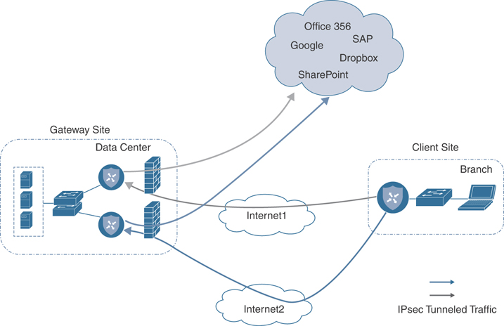
Figure 11-4 Cloud Access Through a Gateway
Finally, a third deployment model, the hybrid approach, makes it possible to have a combination of DIA sites and client/gateway sites. When you define both DIA sites and gateway sites, SaaS applications can use either the DIA exits of the remote site or the gateway sites for any given application, depending on which path provides the best performance. DIA sites are technically a special case of a client site, but the Internet exits are local instead of remote.
Note
At the time of this writing, the following SaaS applications are supported: Intuit, Concur, Oracle, Amazon AWS, Salesforce, Zendesk, Dropbox, Sugar CRM, Office 365, Zoho CRM, Google Apps, Box, and GoTo Meeting.
The Cloud onRamp for SaaS feature actively monitors SaaS application performance from each site over multiple paths. The WAN Edge router views performance statistics differently, depending on whether it is part of a DIA, gateway, or client site. A DIA or gateway site calculates performance statistics of the SaaS application directly, but a client site does not. SaaS performance from a client site depends on the SaaS application performance from a gateway site, plus the performance of the path from the client site to that gateway site.
In the case of a DIA or gateway site, the WAN Edge router issues numerous HTTP requests to each SaaS application over every available path to the application. Over a 2-minute sliding window, it calculates the average loss and latency for each application and path pair.
Using this data, the WAN Edge router calculates a quality of experience (vQoE) score. To get this score, the WAN Edge router accounts for average loss and latency. vManage then collects this data and keeps a record of expected average loss and latency values for all of the SaaS applications. If the actual measured loss and latency are less than the expected loss and latency, then a vQoE score of 10 is given. If actual loss and latency are more than the expected loss and latency, then a vQoE score that reflects a percentage of the baseline performance on a 10-point scale is assigned.
vManage assigns a color and vQoE status to each application and path. A vQoE score of 8 to 10 is green or good, a score of 5 to 8 is yellow or average, and a score of 0 to 5 is red or bad. For any application, the WAN Edge router takes a moving average over several 2-minute time periods and then picks the path with the higher vQoE score.
Figure 11-5 and Figure 11-6 detail how vQoE is calculated.
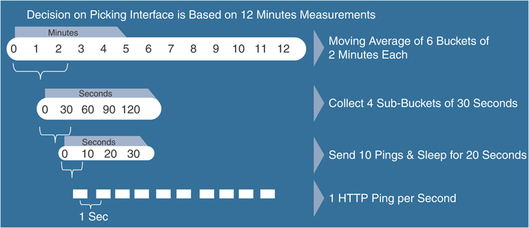
Figure 11-5 vQoE Measurements
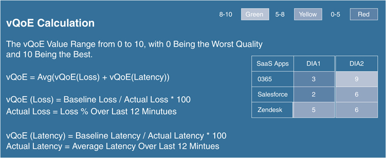
Figure 11-6 vQoE Score Calculation
As covered in the previous section, the gateway site issues HTTP requests directly to the SaaS application and calculates loss and latency of the application, along each of its Internet exit paths. It relays this information back to the client sites via the Overlay Management Protocol (OMP), which runs between the WAN Edge routers and establishes and maintains the control plane in the overlay network. The client site uses Bidirectional Forward Detection (BFD), which runs between WAN Edge routers over the IPsec tunnels to detect loss, latency, and jitter on the path to the gateway site. Figure 11-7 illustrates this process.
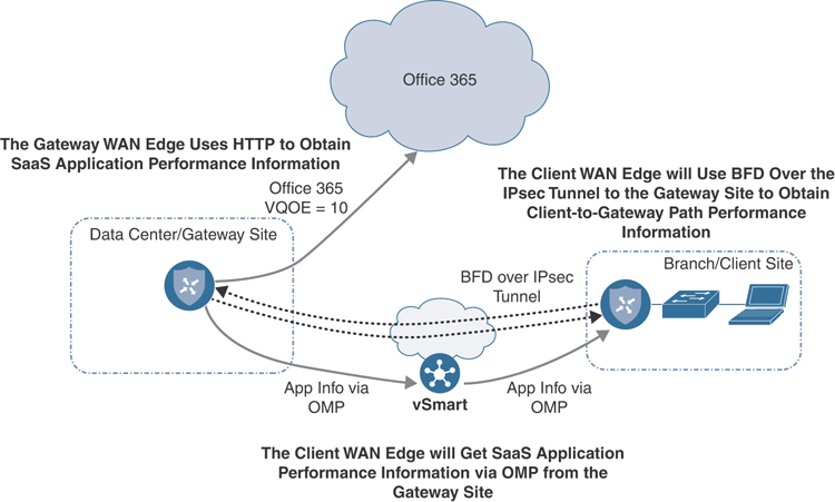
Figure 11-7 Obtaining Performance Metrics for Client/Gateway Sites
DIA sites execute the same probing process for their locally connected Internet circuits in addition to leveraging probe information to and from gateway sites. Figure 11-8 illustrates this process.
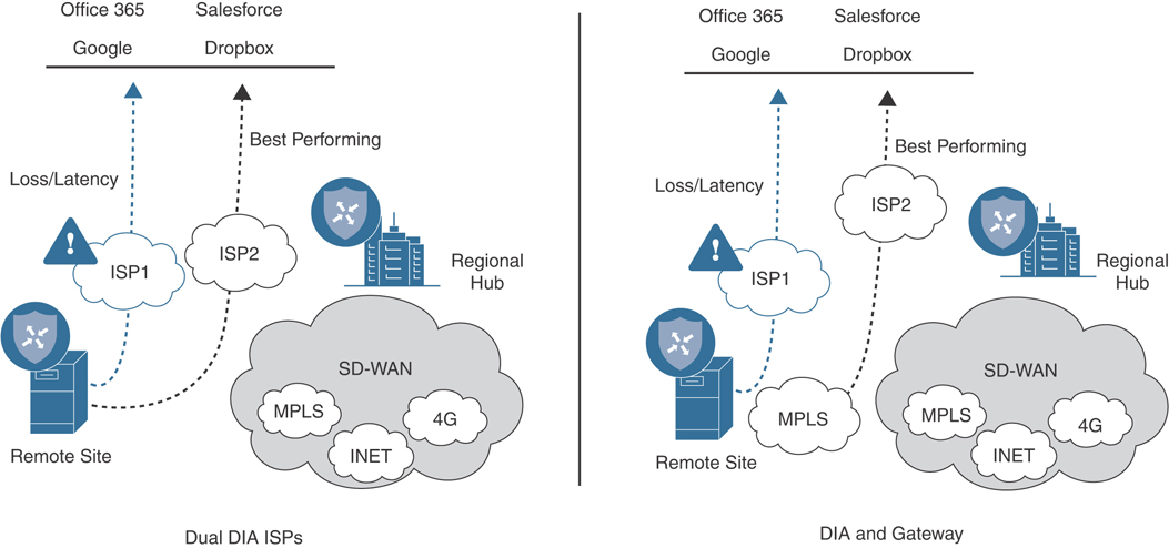
Figure 11-8 Obtaining Performance Metrics for DIA sites
Cisco SD-WAN Deep Packet Inspection (DPI) identifies SaaS applications. When a flow starts for the first time, the traffic takes the path indicated by the routing table. After a couple of packets, DPI identifies the application and stores its identity in a cache so that any subsequent flows going to that destination are sent out the optimal exit determined by the vQoE score, instead of the normal routed path. DPI does not redirect the initial application flow because the redirection would cause network address translation (NAT) changes that would break TCP. Figure 11-9 shows how Cloud onRamp for SaaS handles the application flow.
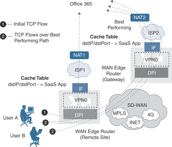
Figure 11-9 Cloud onRamp for SaaS and NAT
Note
For dual WAN Edge sites: Because DPI is used to classify flows on a WAN Edge device, it is important for traffic to be symmetric; that is, DPI should be able to see both request and response traffic. If traffic from a branch office takes a routed path to the Internet out of one WAN Edge routers but the return traffic comes back through a different WAN Edge router, DPI may not be able to classify the traffic correctly so that a local exit or gateway can be chosen for it. It will continue to be routed normally. Care should be taken with routing metrics to ensure symmetry for normally routed traffic.
In order to reach the SaaS applications to calculate performance statistics in the case of gateway and DIA sites, the WAN Edge router needs to first resolve the names of the Cloud onRamp SaaS applications into IP addresses. It performs this task by using the Domain Name System (DNS) server addresses defined in VPN 0. The router initiates a separate DNS query to the same application on each of its local Internet exits. When a host at a site issues a DNS query, the DPI engine intercepts it. If the local DIA Internet exit is the best path and if the query is for a Cloud onRamp SaaS application, the WAN Edge router acts as a proxy and overrides the user DNS settings by forwarding the query to the DNS server defined under VPN 0 over the best-performing DIA Internet exit. If the best path is through a gateway WAN Edge router, then the DNS query is forwarded to the gateway, which intercepts it and forwards it to the DNS server under VPN 0 over its best-performing Internet exit. The DPI engine forwards any DNS queries for non-Cloud onRamp applications normally according to the routing table.
Figure 11-10 illustrates this point.
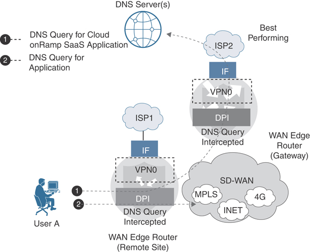
Figure 11-10 Cloud onRamp for SaaS DNS Interception
Because of the built-in workflows integrated into vManage, configuring Cloud onRamp for SaaS is very simple. However, before configuration can begin, several prerequisites must first be met. The lists that follow describe these prerequisites.
Note
The information presented in this section of the book has been adapted from the Cloud onRamp for SaaS Validated Design Guide. For detailed step-by-step instructions and more technical tips, refer to the Validated Design Guide found on Cisco.com.
Prerequisites for all site types (DIA, client, or gateway):
WAN Edge routers need to be in vManage mode as opposed to CLI mode. Simply attach a template to the WAN Edge router and it will be in vManage mode.
The minimum Viptela OS WAN Edge router software version is 16.3.0 to configure DIA sites and 17.1.0 to configure gateway sites, but you should use the latest recommended maintenance release. The minimum IOS-XE WAN Edge router software version is 17.2.1, but you should use the latest recommended maintenance release.
A default route that directs traffic out to the Internet (perhaps through a data center, regional hub, carrier-neutral facility, or even locally) and can reach the SaaS applications must be present in the service VPNs before you configure the Cloud onRamp for SaaS feature. The first couple of packets need to take the traditional routing path before the Cisco SD-WAN DPI engine can identify the application and cache it so that subsequent flows can be directed to the Internet by a DIA path or a gateway site path, whichever is more optimal at that time. The initial flow continues to take the routed path until completion.
Prerequisites for DIA or gateway sites only:
Network address translation (NAT) configuration: In order for SaaS traffic to be able to exit the site locally (for both DIA and gateway sites), NAT configuration is required under each VPN 0 physical interface attached to the Internet or Internet path. This requirement is necessary for the interface to be a candidate for local exit, regardless of any other NAT configured for the site. Enabling NAT, by default, causes translation of the source IP address of a site user to the outside IP address of the WAN Edge router when it uses the interface as a local exit to the SaaS applications.
Default route for local exit: You must have at least one default route defined under VPN 0 to allow the tunnel to connect to the remote sites and data centers through one or more of the physical interfaces. You can either statically define the configuration of this default route or obtain it via Dynamic Host Configuration Protocol (DHCP). For DIA and gateway sites, this default route gives the next-hop information for the direct Internet exits when the Cloud onRamp for SaaS feature is configured.
DNS server defined in VPN 0.
The following is a summary of steps required to configure Cloud onRamp for SaaS in Cisco vManage:
Step 1. Enable Cloud onRamp for SaaS globally. In the vManage Settings page, enable Cloud onRamp for SaaS.
Step 2. Define the SaaS applications. Define a list of SaaS applications to be monitored.
Step 3. Configure DIA sites (optional). Select the sites that will be configured as DIA sites.
Step 4. Configure gateway sites (optional). Select the sites that will be configured as gateway sites.
Step 5. Configure client sites (optional). Select the sites that will be configured as client sites.
First, start by enabling Cloud onRamp for SaaS globally by navigating to the Settings section of vManage, as shown in Figure 11-11.
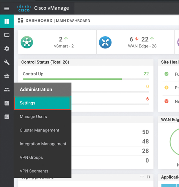
Figure 11-11 vManage Settings Page
Enable Cloud onRamp for SaaS and save the changes, as shown in Figure 11-12.
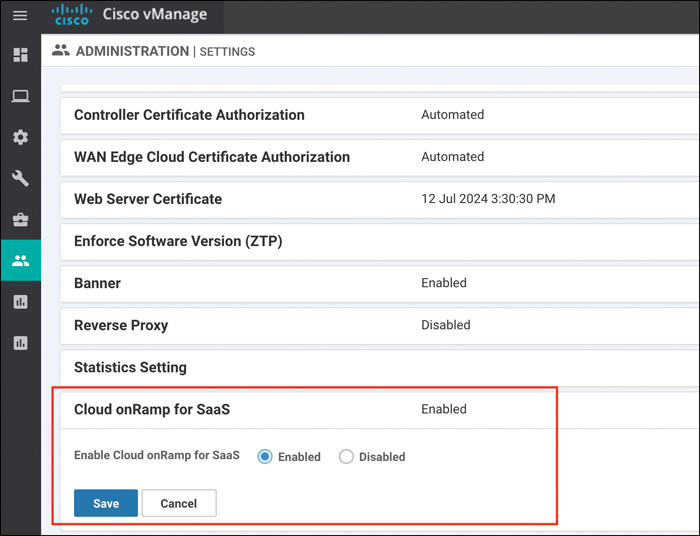
Figure 11-12 Enabling Cloud onRamp for SaaS Globally
To define the SaaS applications, first select the cloud icon at the top of the vManage GUI window and then select Cloud onRamp for SaaS, as shown in Figure 11-13. Alternatively, you can go to Configuration > Cloud onRamp for SaaS from the menu on the left side of the GUI.
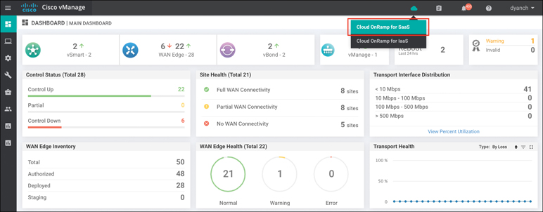
Figure 11-13 Accessing Cloud onRamp for SaaS
A screen pops up that welcomes you to Cloud onRamp for SaaS, states that Cloud onRamp for SaaS has been enabled, and instructs you to add applications and VPNs, client sites, gateways, and DIA sites; it invites you to start using Cloud onRamp for SaaS through the dashboard. Click the Manage Cloud onRamp for SaaS drop-down menu and select Applications to enable the desired SaaS applications, as shown in Figure 11-14.
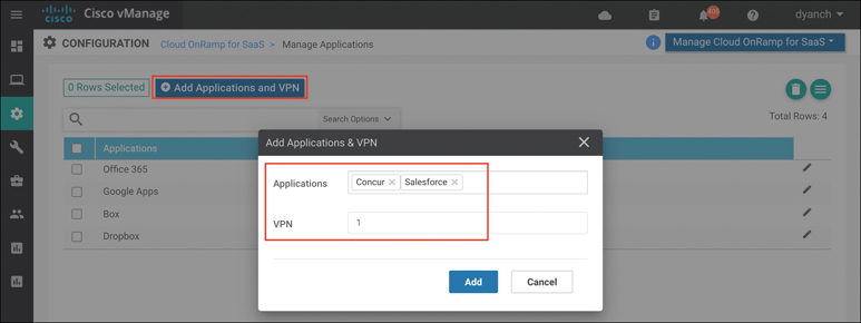
Figure 11-14 Defining Applications
If the goal is to configure Direct Internet Access (DIA) sites, navigate to the DIA sites section under the Manage Cloud onRamp for SaaS screen, as shown in Figure 11-15.
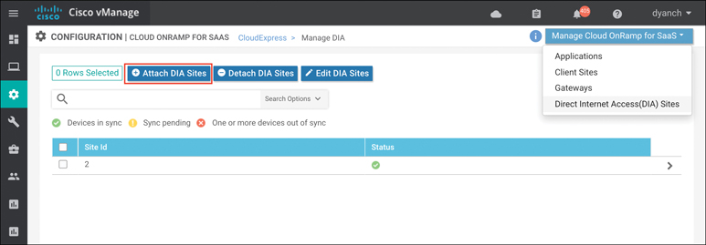
Figure 11-15 DIA Site Configuration
Attach the sites that are deemed to be DIA sites so that vManage and vSmart can push the appropriate configuration and policy to the devices, as shown in Figure 11-16.
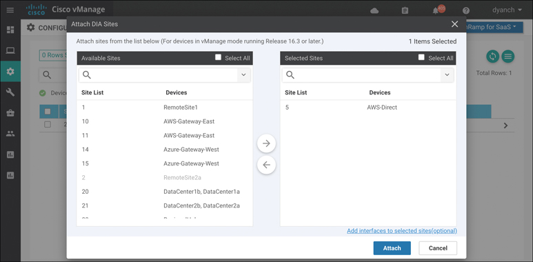
Figure 11-16 Attaching DIA Sites
Optionally, to configure specific interfaces for DIA, select Add Interfaces to selected sites at the bottom of the pop-up screen. Select the WAN Edge router interfaces in the textbox drop-down menu that you will use as direct exits for the SaaS applications, as shown in Figure 11-17. Select Save Changes.
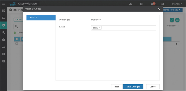
Figure 11-17 Adding Optional DIA Interfaces
Using the Task View section of vManage, verify that all configurations and policies have been pushed out successfully, as shown in Figure 11-18. This process can take 30 seconds or longer.
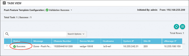
Figure 11-18 Cloud onRamp for SaaS Configuration Push
If you’re configuring gateway sites, follow the preceding instructions after navigating to the Gateways section and clicking Attach Gateways, as shown in Figure 11-19.
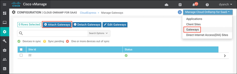
Figure 11-19 Gateway Site Configuration
If you’re configuring client sites, follow the preceding instructions after navigating to the Client Sites section and clicking Attach Sites, as shown in Figure 11-20. Selecting interfaces will not be available when configuring a client site since client sites do not break out locally.
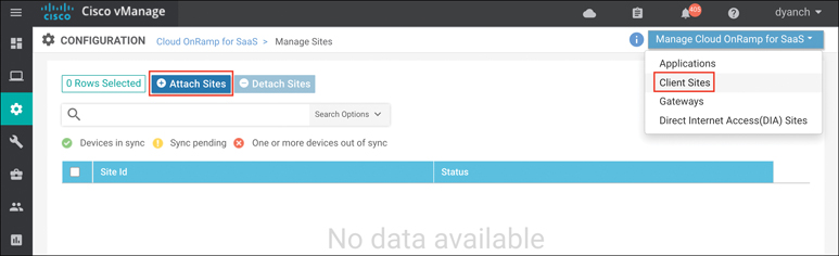
Figure 11-20 Client Site Configuration
vManage provides built-in monitoring for Cloud onRamp for SaaS. When you monitor Cloud onRamp for SaaS, you can view vQoE performance scores, view the network path selected for each application and site, and view the detailed loss and latency data for each application and path as well.
The main Cloud onRamp for SaaS page displays each configured SaaS application as a widget. Each widget lists the number of active sites, WAN Edge devices that use that application, and the number of WAN Edge devices that show vQoE scores in the good, average, and bad ranges, as shown in Figure 11-21. Note that these vQoE scores are shown only for the best-performing path according to each WAN Edge device.
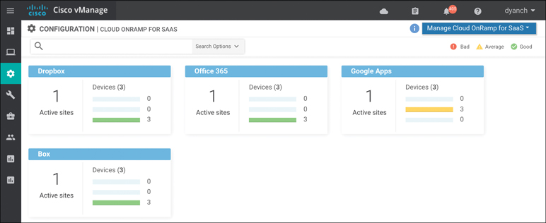
Figure 11-21 Cloud onRamp for SaaS Monitoring
From this page, select an application widget to get additional details about the vQoE scores and optimal paths selected. The resulting page will show the list of sites, the WAN Edge name, the vQoE status (a symbol indicating good, average, or bad), the vQoE number score, 410and the optimal path in use (local exit or gateway, selected local interface or system IP of the gateway, and an indication of the IPsec tunnel transports used to reach the remote gateway), as shown in Figure 11-22.
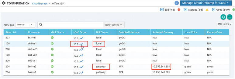
Figure 11-22 Application-Specific Performance by Site
If you select an arrow under the vQoE score column, a window will pop up to show the vQoE score history on a graph. You can see a 1-, 3-, 6-, 12-, or 24-hour view, a 7-day view, or a custom view of this data, as shown in Figure 11-23.
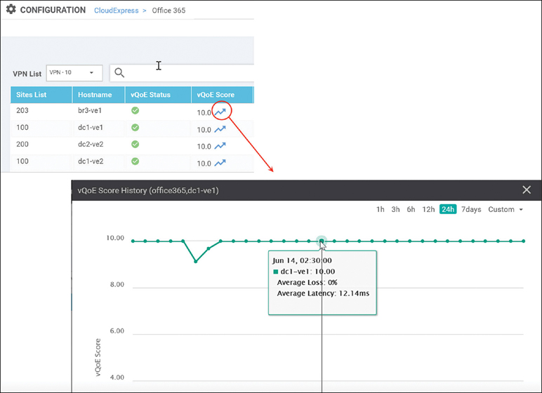
Figure 11-23 Historical Application Performance
You can make vManage display detailed loss and latency data on a per-SaaS-application basis by navigating to the device dashboard and selecting the Real Time option. The CloudExpress Applications output shows each application, the optimal path that has been chosen, and the mean latency and loss associated with the application for each optimal path, as shown in Figure 11-24.
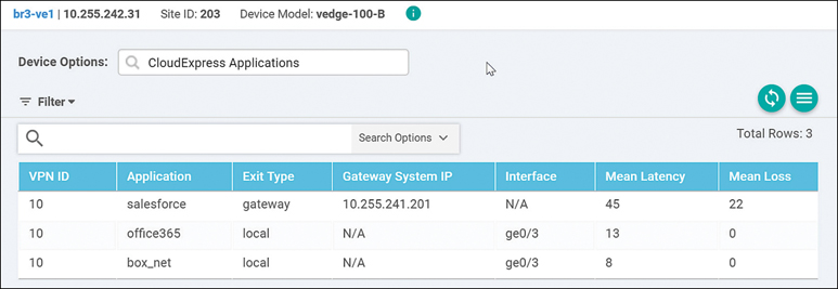
Figure 11-24 Real-Time CloudExpress Applications
The CloudExpress Gateway Exits output shows each application, what the gateway exits are, and the mean latency and loss associated with the application for each gateway path available, as shown in Figure 11-25. It also indicates the tunnel transport that is taken to reach the gateway site (Local Color/Remote Color columns).
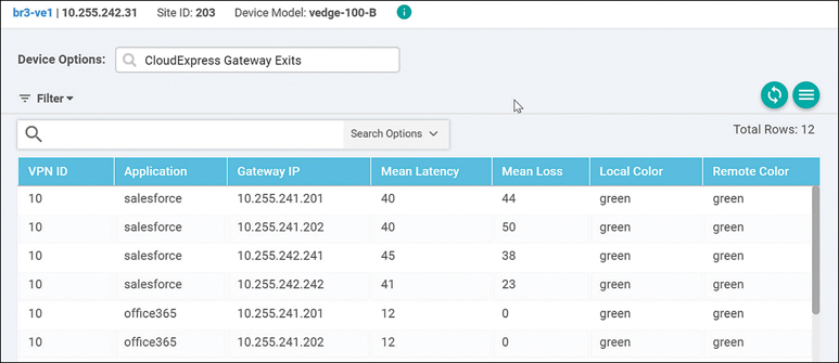
Figure 11-25 Real-Time CloudExpress Gateway Exits
The CloudExpress Local Exits output shows each application and the mean latency and loss associated with each of its local Internet exits, as shown in Figure 11-26.
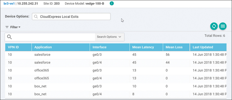
Figure 11-26 Real-Time CloudExpress Local Exits
Finally, the OMP CloudExpress Routes output shows the OMP routes received from the various gateways and the mean latency and loss associated with the applications and paths originating from them, as shown in Figure 11-27.
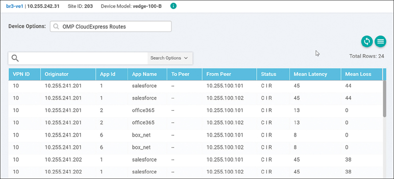
Figure 11-27 Real-Time CloudExpress Routes
Cloud onRamp for IaaS
In a multi-cloud world, organizations are quickly realizing the benefits of cloud computing services by leveraging Infrastructure as a Service (IaaS). IaaS providers, such as Amazon Web Services (AWS) and Microsoft Azure, allow organizations to more rapidly and cost-effectively develop and deliver new applications. Instead of procuring, installing, and managing hardware, which could take months to accomplish, you can easily use the on-demand and scalable compute services in an IaaS environment. This allows you to focus your resources on applications rather than on managing the data center and physical infrastructure. With the use of IaaS, expenses shift from fixed costs for hardware, software, and data center infrastructure to variable costs based on the usage of compute resources and the amount of data transferred between the private data center, campus, branch locations, and the IaaS cloud provider. Because of this new consumption model, you must be able to monitor the usage of such resources for cost tracking and/or internal billing purposes.
A virtual private cloud (VPC) is an on-demand virtual network, logically isolated from other virtual networks within a public cloud. Most public IaaS cloud providers, such as AWS, allow traffic to flow between different virtual private clouds within a single region and recently between regions through VPC peering connections. However, AWS does not allow traffic to transit through a VPC, meaning traffic must either originate or terminate within a VPC, not simply pass through it. This means that as the number of VPCs increases, the amount of peering between the VPCs increases dramatically, if full-mesh connectivity between VPCs is a requirement.
Cloud onRamp for IaaS extends the fabric of the Cisco SD-WAN overlay network into public cloud instances, allowing branches with WAN Edge routers to connect directly to public cloud application providers. By eliminating the need for a physical data center, Cloud onRamp for IaaS improves the performance of applications hosted in the cloud.
Note
At the time of this writing, both Amazon Web Services (AWS) and Microsoft Azure IaaS environments are supported by Cloud onRamp for IaaS. Other IaaS providers will be supported in later releases. This section of the chapter will focus on demonstrating how Cloud onRamp for IaaS is deployed for an AWS environment only, but the process is virtually the same for Microsoft Azure.
Cloud onRamp for IaaS is designed to alleviate design and scale issues by provisioning a transit VPC within the IaaS public cloud provider. A transit VPC is a VPC that has the single purpose of transporting traffic between other VPCs as well as campus and branch locations.
Figure 11-28 illustrates this design.
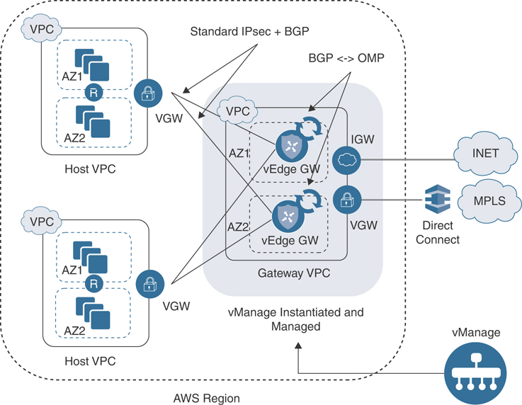
Figure 11-28 Cloud onRamp for IaaS Design
Within the Cisco Cloud onRamp workflow, one or more cloud instances can be created. Each cloud instance corresponds to an AWS account and region in which one or more transit VPCs can be created and to which one or more host VPCs can then be mapped. Multiple AWS accounts can be added to Cisco Cloud onRamp by adding either AWS Identity and Management (IAM) roles or access keys. These are used by Cisco Cloud onRamp to make the necessary application programming interface (API) calls to create the transit VPC and map host VPCs to the transit VPC.
A pair of redundant Cisco WAN Edge Cloud routers is implemented within a VPC dedicated to function as a transit point for traffic between host VPCs. The Cisco WAN Edge Cloud routers are each deployed within a different availability region within the transit VPC for greater resilience in case of failure. Each Cisco WAN Edge Cloud router is automatically provisioned with the following:
A management VPN (VPN 512), available via an AWS elastic IP address (public IP address)
A transport VPN (VPN 0), also available via an AWS elastic IP address
One or more service VPNs (VPNs 1, 2, and so on)
The transit VPC also provides the entry point from AWS into the Cisco SD-WAN Secure Extensible Network (SEN). The AWS VPN gateway at each host VPC establishes redundant site-to-site VPN connections to each Cisco WAN Edge Cloud router within the transit VPC, through the service VPN side of the Cisco WAN Edge Cloud routers.
When you map a host VPC to the transit VPC, Cisco Cloud onRamp uses AWS APIs to automatically create a redundant pair of AWS site-to-site VPN connections at the host VPC. Each AWS IPsec VPN connection is mapped to one of the two Cisco WAN Edge Cloud routers within the transit VPC. Each Cisco WAN Edge Cloud router within the transit VPC functions as a customer gateway from an AWS perspective. Each AWS site-to-site VPN connection consists of a pair of IPsec tunnels established to the same customer gateway. Therefore, a total of two IPsec tunnels is established from each host VPC to the transit VPC.
Figure 11-29 illustrates this point.
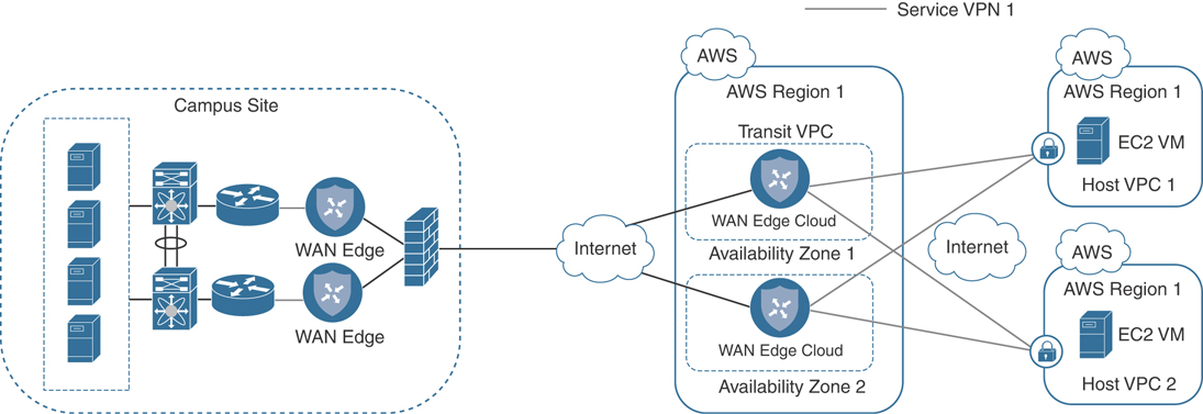
Figure 11-29 Cloud onRamp for IaaS Single Segment
Multiple host VPCs can be mapped to the same service VPN at the transit VPC. This provides connectivity between the host VPCs. Alternatively, individual host VPCs can be mapped to separate service VPNs at the transit VPC—if network segmentation is required.
Figure 11-30 illustrates this point.
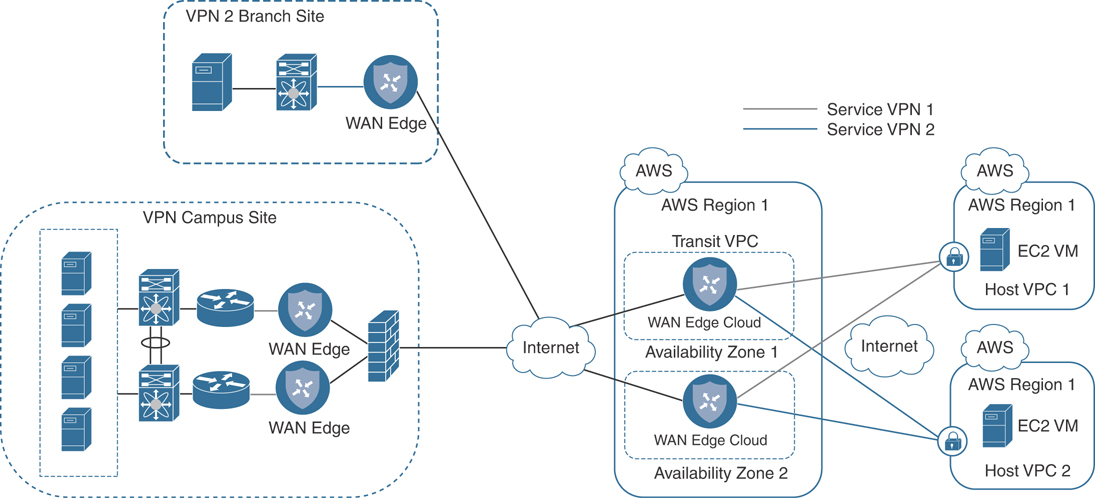
Figure 11-30 Cloud onRamp for IaaS Multi Segment
Because of the built-in workflows integrated into vManage, configuring Cloud onRamp for IaaS is very simple. However, before configuration can begin, several prerequisites must first be met:
Verify you have available tokens/licenses for two additional Cisco WAN Edge Cloud routers in vManage.
Configure a device template for the Cisco WAN Edge Cloud routers that will be used within the transit VPC.
Deploy the device template to the Cisco WAN Edge Cloud routers that will be used within the transit VPC. You cannot complete the Cloud onRamp for IaaS workflow unless the virtual WAN Edges being deployed have templates with a basic configuration attached to them. A sample base template can be found in the Cloud onRamp for IaaS Deployment Guide accessible on Cisco.com.
Verify you meet the AWS prerequisites such as elastic IP limits, VPC limits, and so on.
Note
The information presented in this section of the book has been adapted from the Cloud onRamp for IaaS Deployment Guide. For detailed step-by-step instructions and more technical tips, refer to the Deployment Guide found on Cisco.com.
The following is a summary of steps required to configure Cloud onRamp for IaaS:
Step 1. Add a new cloud instance. Navigate to the Cloud onRamp for IaaS workflow and begin the workflow.
Step 2. Select the cloud provider and configure access credentials. Select either AWS or Azure and provide the API key.
Step 3. Add a transit VPC. Select a region and create transit VPCs.
Step 4. Discover and map host VPCs to the transit VPC. Map the discovered host VPCs to the desired transit VPC.
Begin by navigating to the Cloud onRamp for IaaS section of vManage and selecting Add New Cloud Instance to start the workflow. Cloud onRamp for IaaS can be found either under the Configuration tab of vManage, as shown in Figure 11-31, or by clicking the cloud icon at the top right of the screen and selecting Cloud Onramp for IaaS.
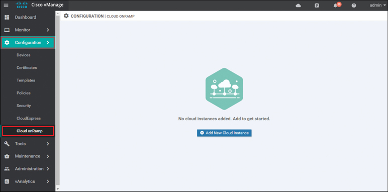
Figure 11-31 Cloud onRamp for IaaS Navigation
Select the cloud provider from the screen in Figure 11-32. For the purposes of this example, Cloud onRamp for IaaS using Amazon Web Services will be selected and deployed.
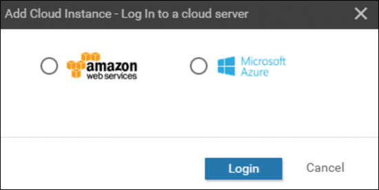
Figure 11-32 Add Cloud Instance
Cisco Cloud onRamp uses API calls to create the AWS transit VPC with two Cisco WAN Edge Cloud router instances as well as to map existing AWS spoke VPCs to the transit VPC. Either an AWS Identity and Management (IAM) role or an access key can be used to make the necessary API calls. In the example in Figure 11-33, an access key for AWS credentials will be used. The Cloud onRamp for IaaS Deployment Guide discusses how to generate the access key if you do not already have one.
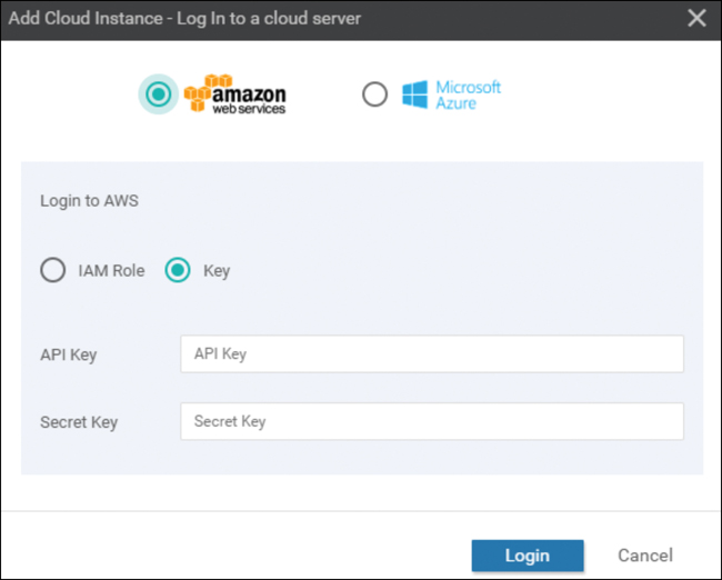
Figure 11-33 Log in to a Cloud
Enter the AWS access key ID in the API Key field, and enter the AWS secret access key in the Secret Key field shown in Figure 11-33. Click the Login button when you have entered the AWS credentials.
Upon entering your AWS credentials, you will be taken to the next step in the workflow: adding a transit VPC.
From the drop-down menu next to Choose a Region, select the AWS region in which you want to create a transit VPC, as shown in Figure 11-34. The following information must be provided to continue the deployment:
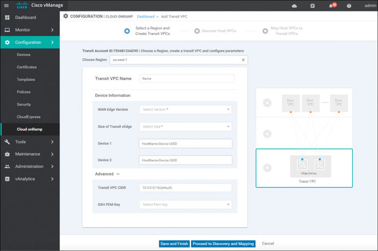
Figure 11-34 Add a Transit VPC
Transit VPC Name: This is the name of the transit VPC created by Cisco Cloud onRamp within AWS.
WAN Edge Version: This is the version of software that will run on the redundant pair of Cisco WAN Edge Cloud routers. Once the Cisco WAN Edge Cloud routers are running within the transit VPC, if necessary, you can upgrade the code version they are running to a higher release through vManage.
Size of Transit vEdge: This is the type of AWS compute resource allocated to the WAN Edge cloud routers. The larger the C4 instance, the more vCPUs, memory, and network performance but at a higher per-hour rate.
Device 1 and Device 2: These are the unused and licensed WAN Edge Cloud routers previously deployed with a basic template. The UUID of these routers should populate the drop-down.
Transit VPC CIDR (optional): The default CIDR for the transit VPC is 10.0.0.0/16. There must be sufficient address space to create six subnets within the CIDR block. Only IPv4 addressing is supported.
SSH PEM Key: By default, AWS EC2 instances are accessed using an SSH keypair. This is different from the AWS credentials discussed earlier. You must have an SSH keypair already configured under the same user ID used for the AWS access key discussed earlier. Refer to the Cloud onRamp for IaaS Deployment Guide for detailed instructions on how to generate an SSH keypair in AWS.
Once you have filled in the fields, you can choose to create just the transit VPC at this time by clicking the Save and Finish button. Alternatively, you can choose to proceed to the discovery and mapping of spoke VPCs to the transit VPC by selecting the Proceed to Discovery and Mapping button. In this example, the host VPCs are mapped to the transit VPC in a separate procedure.
After a few minutes, the Task View screen should appear, confirming that the transit VPC with a redundant pair of Cisco WAN Edge Cloud routers has been created within AWS, as shown in Figure 11-35.
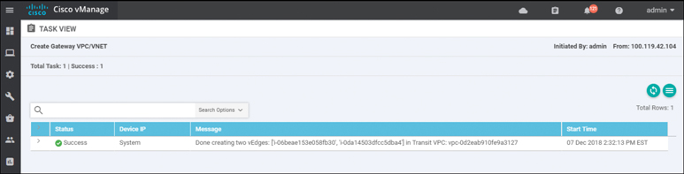
Figure 11-35 Successful Creation of a Transit VPC
Note
Note that the configuration deployed on the Cisco WAN Edge Cloud routers within the transit VPC can be modified at any time by making the appropriate changes to the template within vManage and deploying the changes to the devices.
Before host VPCs can be mapped to the transit VPC, they must first be discovered within Cisco Cloud onRamp. In the navigation panel on the left side of the screen, select Configuration and then select Cloud onRamp. This will bring you to the initial Cisco Cloud onRamp screen, as shown in Figure 11-36.
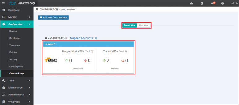
Figure 11-36 Cloud onRamp for IaaS Existing Cloud Instance
The IaaS cloud instance created in the previous procedure will appear when the Transit View tab is selected. As you can see in Figure 11-36, a single AWS cloud instance now exists. You can verify which AWS region the cloud instance resides in by clicking the Mapped Accounts link shown in Figure 11-36. Within this cloud instance, a single transit VPC with two Cisco WAN Edge Cloud routers has been created. Both Cisco WAN Edge Cloud routers are up, as indicated by the green arrow.
At this point, there are no host VPCs mapped to the transit VPC within the cloud instance. Host VPCs connect to the transit VPC through AWS site-to-site VPN connections that use elastic IP addresses (publicly routable IP addresses) at the transit VPC. Host VPCs must first be discovered and then mapped to the transit VPC.
Click the AWS cloud instance widget to which you wish to map host VPCs within the Cisco Cloud onRamp screen. This will bring up additional details regarding the cloud instance. Figure 11-37 shows an example.
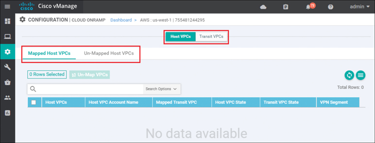
Figure 11-37 Mapped Host VPCs
The details screen has two tabs: Host VPCs and Transit VPCs. In Figure 11-37, the Host VPCs tab is selected. The Host VPCs tab has two subtabs: Mapped Host VPCs and Unmapped Host VPCs. By default, the Mapped Host VPCs subtab is selected. As can be seen in Figure 11-37, no host VPCs are currently mapped to the transit VPC within the cloud instance.
Multiple transit VPCs can be configured within a single cloud instance (AWS account within a region). When multiple transit VPCs exist within a cloud instance, host VPCs can be mapped to any one of the transit VPCs.
Select the Un-Mapped Host VPCs tab. The screen will change to look as shown in Figure 11-38.
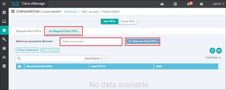
Figure 11-38 Un-Mapped Host VPCs Tab
Host VPCs must first be discovered by Cisco Cloud onRamp before they can be mapped to a transit VPC. The discovery process uses AWS API calls to discover the VPCs within the AWS account you select.
From the drop-down menu next to Select one account, select the account from which you wish to discover host VPCs.
When you entered the AWS credentials within this deployment guide, they were associated with an AWS account. The AWS account number associated with this account should appear within the drop-down menu. You can also enter new accounts by clicking in the New Account button at the bottom of the drop-down menu. A pop-up screen asking for the account credentials will appear, as shown in Figure 11-39.
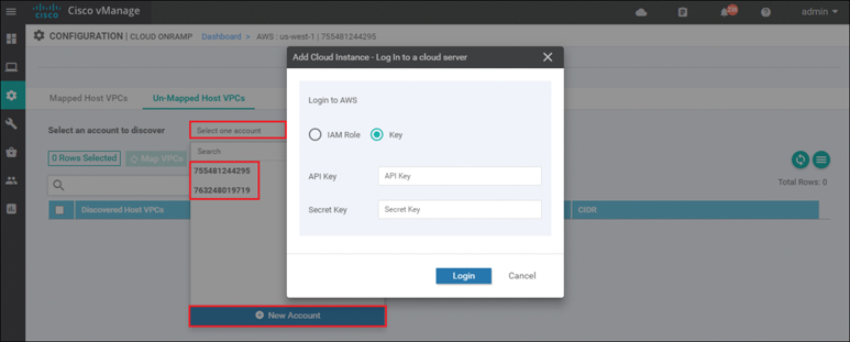
Figure 11-39 Add a New Account
For this example, the host VPCs were created under the same account as the transit VPC.
Click the Discover Host VPCs button. The screen should update to show the VPCs available to be mapped to a transit VPC. Figure 11-40 shows an example.
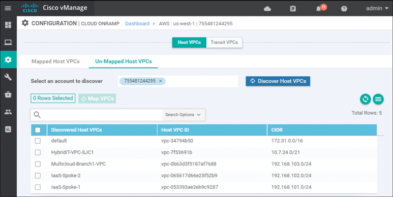
Figure 11-40 Discovered VPCs
Note
Only VPCs within the AWS account selected and within the same AWS region as the transit VPC will appear. VPCs must also have a name tag associated with them within AWS for them to appear within Cisco Cloud onRamp. The default VPC automatically created by AWS for each region typically does not have a name tag associated with it. If you want the default VPC for the AWS region to appear within the list of VPCs to map to the transit VPC, you must assign a name tag to it within AWS before it can be discovered.
Select the host VPCs that you want to map and click the Map VPCs button, as shown in Figure 11-41.
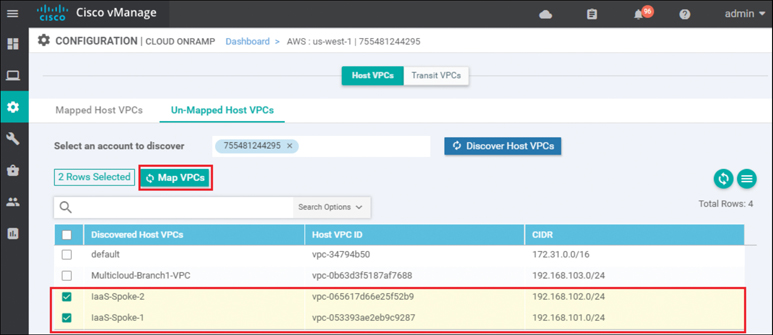
Figure 11-41 Map VPCs
For this example, both host VPCs IaaS-Spoke-1 and IaaS-Spoke-2 were selected from the preceding picture. The pop-up screen in Figure 11-42 will then appear.
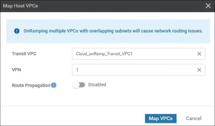
Figure 11-42 Transit VPC Mapping Details
If there is only one transit VPC configured within the cloud instance, the Transit VPC field will be filled in for you. If there are multiple transit VPCs within the cloud instance, then from the drop-down menu select the transit VPC to which you wish to map the host VPC.
You have the choice of mapping the host VPC to any of the service VPNs you have defined within the device template attached to the Cisco WAN Edge Cloud router instance. Each host VPC can be mapped to a single service VPN. Mapping host VPCs to the same service VPN allows communication between the host VPCs. Mapping host VPCs to different service VPNs provides network isolation of the host VPCs from each other and allows only branch and campus sites with the same service VPN to access the host VPC.
Enabling Route Propagation will propagate the BGP routes to both host VPCs. By default, Route Propagation is disabled.
Click the Map VPCs button. After a few minutes, the Task View screen should appear, confirming that the host VPC has been mapped to the transit VPC, as shown in Figure 11-43.
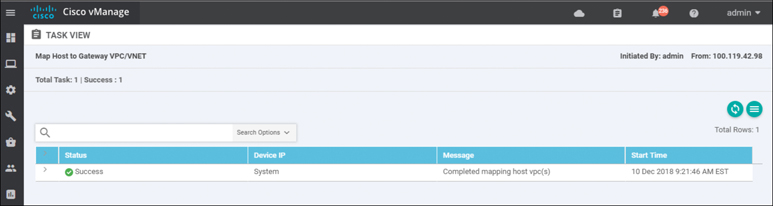
Figure 11-43 Successful Mapping of Both Host VPCs to the Transit VPC
When you monitor Cisco Cloud onRamp, you can view the following:
The connectivity state of each host VPC
The state of the transit VPC
Detailed traffic statistics for the IPsec VPN connections between the transit VPC and each host VPC
To view the connectivity state of each host VPC, select the cloud icon at the top of the vManage GUI and then click Cloud onRamp for IaaS. You will come to a page displaying each configured cloud instance as a widget. Each widget will list how many host VPCs are mapped to any of the transit VPCs within the cloud instance as well as how many transit VPCs are defined for the cloud instance. Figure 11-44 shows an example.
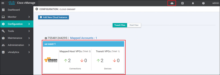
Figure 11-44 Cloud Instance Widget
The aggregate number of host VPCs that are reachable is indicated with a green “up” arrow under Mapped Host VPCs. Likewise, the aggregate number of host VPCs that are unreachable is indicated with a red “down” arrow. The color-coded up and down arrows indicate whether the IPsec VPN tunnels connecting the host VPC with the transit VPC are up or down.
The aggregate number of Cisco WAN Edge Cloud routers that are reachable is indicated with a green up arrow under Transit VPCs. Likewise, the aggregate number of Cisco WAN Edge Cloud routers that are unreachable is indicated with a red down arrow. In the case of transit VPCs, the color-coded up and down arrows indicate whether the logical Cisco WAN Edge Cloud router is reachable or not. Generally, reachability indicates whether the Cisco WAN Edge Cloud router is running or not. Since there are two Cisco WAN Edge Cloud routers per transit VPC, the number of devices shown here should be twice the number of transit VPCs.
Although the widget can be used to quickly display whether any of the Cisco WAN Edge Cloud routers is down/unreachable or whether any of the host VPCs is unreachable, it does not tell you which specific Cisco WAN Edge Cloud router is down/unreachable or which host VPC is unreachable. For this information you must look further within the cloud instance.
Click the IaaS cloud instance deployed. You can see specific details regarding whether individual host VPCs are up or down as well as their associated transit VPC. You can also see which service VPN the host VPC is mapped to at the transit VPC. Figure 11-45 shows an example.
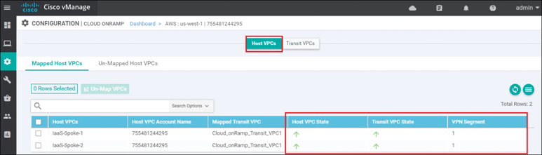
Figure 11-45 Per-Host State Details
When you click the Transit VPCs tab, you will be taken to a screen that displays the state of each transit VPC within the cloud instance. Figure 11-46 shows an example.
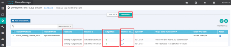
Figure 11-46 Transit VPC State
Although the more detailed information discussed in the previous procedure is useful in determining if a given Cisco WAN Edge Cloud router is up or down, it doesn’t provide any information regarding the traffic between the transit VPC and each host VPC.
Click the graph icon for one of the Cisco WAN Edge Cloud routers under the Interface Stats column shown in Figure 11-46.
A pop-up screen displaying statistics for the IPsec VPN connections between the Cisco Cloud onRamp router and the host VPC(s) is displayed. Figure 11-47 shows an example.
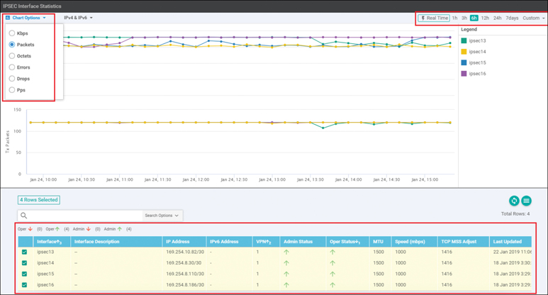
Figure 11-47 Host VPC VPN Statistics
Statistics are displayed in both the transmit and receive directions—from the perspective of the Cisco WAN Edge Cloud router logical IPsec interfaces configured within the transit VPN. By default, statistics are displayed for all IPsec interfaces. You can remove an interface from the graph by unselecting it in the panel below the graph.
Cloud onRamp for Colocation
The traditional architectural method of delivering traffic optimization (such as load balancing, security policy, WAN optimization, and so on) relied on centralized provisioning of elements, such as firewalls, intrusion detection/prevention sensors, data leak prevention systems, URL filtering, proxies, and other such devices at aggregation points within the network (most commonly the organization’s data centers). For SaaS applications and Internet access, this approach resulted in backhauling user traffic from remote sites into the main data centers, which increased application latency and negatively impacted overall user experience. For applications hosted in the data center, this approach resulted in the potential waste of data center bandwidth resources. Additionally, this architectural method also proved to be challenging to effectively mitigate security incidents, such as virus outbreaks, malware exploits, and internally sourced denial of service attacks.
Today, as we move into the era of SD-WAN, this problem is exacerbated by the architectural shift into a distributed access model. Branches and users are now free to access SaaS applications and Internet resources directly—bypassing the aggregation points highlighted earlier. While this provides a much more efficient method of moving data from point A to point B, it poses a challenge to IT teams looking to maintain their traditional optimization and security policies.
Figure 11-48 shows how Cloud onRamp for Colocation provides a solution to this problem by creating a hybrid model.
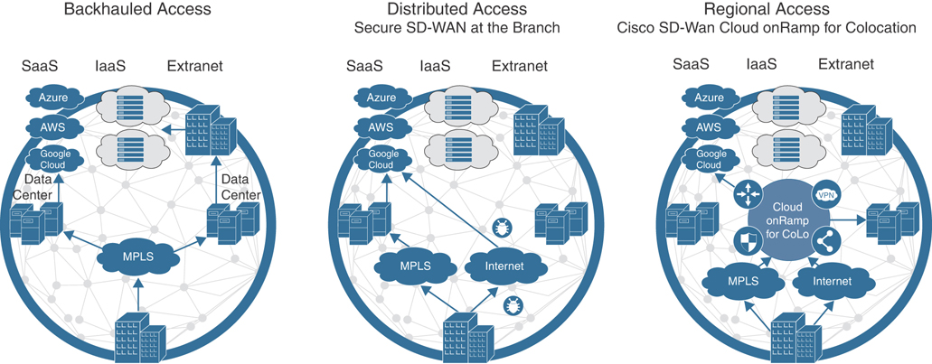
Figure 11-48 The WAN of Yesterday, Today, and Tomorrow
In addition to the challenges previously listed, the following items also create pain points for many customers wishing to optimize cloud access:
It is becoming increasingly difficult to apply optimization policies uniformly across private and public applications.
Some IaaS and SaaS vendors simply do not provide the necessary optimization and security policy sought by many IT teams.
Those IaaS and SaaS providers that do offer optimization and security policies typically do so in a way that is not consistent with your enterprise policy.
Ultimately, there exists an inconsistency in the application of policies across users, devices, applications, and cloud resources.
Cisco SD-WAN offers support for both centralized and distributed architectural models. By leveraging service insertion policies and/or intelligent routing, Cisco SD-WAN can steer traffic of interest wherever necessary to satisfy policy. It is this core function that gave birth to the concept of regionalized service chaining. Coupled with Cisco Cloud onRamp for Colocation, Cisco SD-WAN can establish strategic demarcation points between users/devices and the resources they access. By positioning optimization/security network elements in strategic points across the network, regional service chaining strikes the right balance between operation, cost, application quality of experience, and the ability to effectively mitigate security incidents.
Choosing to move to a regionalized model with service chaining comes with many benefits, such as the following:
Security: Distributed policy enforcement offers simple and secure access, deployment, and control.
Scalable architecture: The flexible architecture of Cloud onRamp for Colocation allows you to scale out as required. Cisco Cloud Services Platform (CSP) negates the need to order, cable, rack, and stack dedicated appliances when capacity needs increase or changes need to be made.
Performance agility: The ability to spin up new network elements on demand offers improved performance agility. Optimize application performance by strategically placing Cloud onRamp for Colocation in colocation centers that are closest to your SaaS and IaaS cloud providers.
Flexibility: The solution supports both Cisco virtual network functions (VNFs) and third-party VNFs.
Cost savings: By having various strategic locations to connect to various clouds (including private clouds), enterprises can optimize the costs of circuits to connect their users to applications. Circuit costs for a colocation facility are significantly lower than in a private data center.
Figure 11-49 shows how traffic shifts from a data center model to a center of data model. Users, devices, and things exist on the left, and the resources they access (centers of data) are shown on the right. Cloud onRamp for Colocation sits on the demarcation between these groups. Any traffic moving from left to right within the drawing must pass through Cloud onRamp to satisfy business policy.
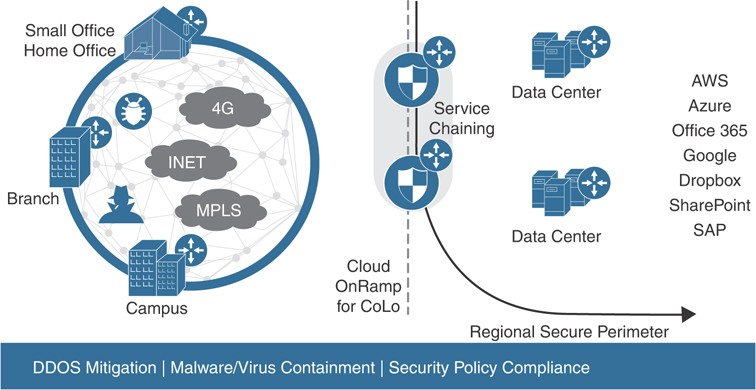
Figure 11-49 Regionalized Service Chaining
Why Colocation?
Colocation centers allow you to rent equipment, bandwidth, or space in a secure public data center. These facilities provide flexibility to directly connect with a variety of telecommunications, network, and cloud service providers at a fraction of what it would cost to run direct connections to a private data center. One of the greatest benefits to utilizing a colocation center, however, is its geographical coverage. A colocation facility not only provides high-speed access into public and private cloud resources, but also its geographical presence ensures that you can strategically select a facility (or multiple facilities) in close proximity to your users. Hence, with Cisco SD-WAN and Cisco Cloud onRamp for Colocation, you can ensure your users’ traffic need only travel a short distance to the nearest colocation—where that traffic will be optimized, further secured, and transmitted to its intended destination over a high-speed backbone.
How It Works
Establishing regional service chaining is a useful approach in maintaining the organization’s optimization and security policies that were once used in a centralized architecture. In this case, policy enforcement can happen on demand by modifying SD-WAN policies to steer application traffic of interest to the nearest colocation facility without the need to re-engineer the network at either remote sites or data centers. Traffic steering can be as granular as a single application or as coarse as the entire remote site’s traffic. Once this traffic reaches the colocation facility, it will be shuttled through the appropriate service chain (hosted by Cisco Cloud onRamp for Colocation) as dictated by SD-WAN policy. It’s important to note that Cisco SD-WAN is not a requirement for Cloud onRamp for Colocation. Cisco SD-WAN greatly simplifies traffic steering, however, and will be the focus of the example for this section.
Initial traffic steering is performed by Cisco SD-WAN Edge routers (running either IOS-XE or Viptela OS). Through intelligent routing, Deep Packet Inspection, and/or service insertion policy, the ingress router will identify the traffic, analyze its destination, and steer the traffic through the nearest colocation facility (when necessary). It is also important to note that this traffic steering is not limited to IaaS, SaaS, or Internet destinations. In fact, organizations seeking to provide inter-site security and optimization can also utilize Cisco Cloud onRamp for Colocation with service chaining, such as when WAN optimization is necessary.
As mentioned, network functions (such as load balancers, IDS/IPS, firewalls, proxies, and so on) are typically virtualized or hosted within Cisco Cloud onRamp for Colocation and are installed in a colocation facility within geographic proximity to the users it will service.
Figure 11-50 shows the high-level architecture of the solution.
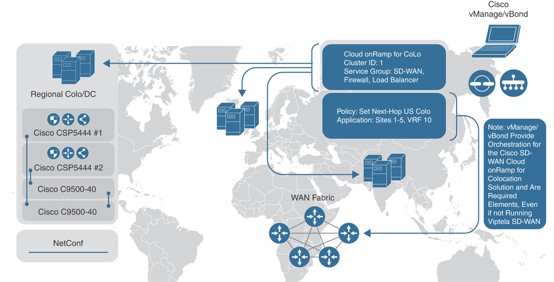
Figure 11-50 High-Level Architectural View
These virtual or physical network services are then directly connected to the Cisco WAN Edge router via the LAN interface. This router then, in essence, announces the presence of these network functions through BGP or OMP service routes (or even via a default route). For traffic that must adhere to a particular optimization or security policy, ingress routers will select the nearest colocation router announcing the presence of these network services and forward their traffic appropriately. Again, strategically placed Cloud onRamp for Colocation clusters allow administrators to minimize the latency penalty for inter-site, Internet, SaaS, and IaaS traffic—thus providing a high quality of experience (QoE) without having to sacrifice security or optimization.
By utilizing this approach, coupled with the templating capabilities of Cisco SD-WAN, administrators can quickly and easily onboard new colocations and/or service chains into the WAN fabric without the need to adjust policy.
Figure 11-51 shows the physical components that make up the solution.
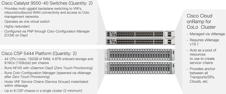
Figure 11-51 Cloud onRamp for Colocation Cluster
Service Chaining for a Single Service Node
In the case of a service chain with a single service node, application traffic of interest is steered from the source WAN Edge router across the SD-WAN fabric to the Colocation Edge router announcing the service. Once the traffic passes through the network service (a firewall, for instance), either it is forwarded back to the Colocation Edge router (which then forwards it to the original destination router across the SD-WAN fabric) or it is forwarded out of the network service chain toward the public cloud/Internet.
Both control and data policies can be used for this type of service chaining. The main difference between them is that data policies are sent from vSmart controllers to the SD-WAN routers, while control policies stay only on the vSmart controllers (that is, similar to how a BGP route reflector would modify routes prior to announcing them to neighbors). Knowing this, it is important to note that with control policies, since vSmart controllers do not “see” actual data packets, matching policy rules can only be on control plane identifiers (such as site IDs, OMP routes, and so on). Data policies do not have this limitation, as these policies are enforced directly on the SD-WAN router.
Figure 11-52 depicts how a single service chain node is inserted into the fabric by leveraging SD-WAN policy.
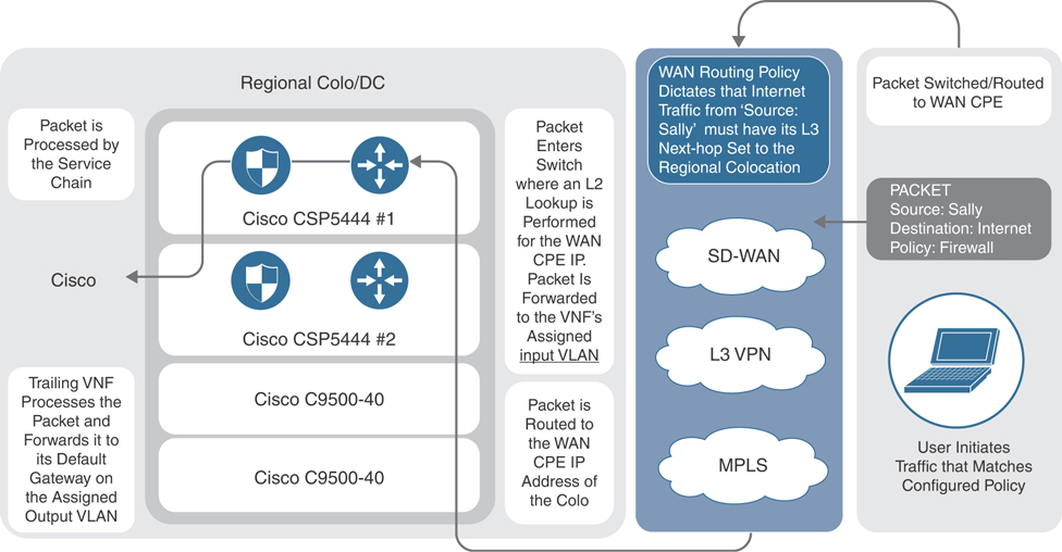
Figure 11-52 Simplified Packet Walkthrough
In all cases, the network service is advertised into the SD-WAN fabric via OMP. Service advertisement is done in the VPN context, which gives service insertion even further flexibility with regard to managed service providers and multitenancy. Not only can service insertion be regionalized, but also different VPNs can potentially utilize different services in the same region. This level of flexibility may not be required for common deployment scenarios.
In the case of a firewall service, Cisco SD-WAN fabric also supports provisioning trusted and untrusted side interfaces. In such a case, policies can be orchestrated in such a way that site-to-site traffic is forwarded across the untrusted zone and trusted zone interfaces appropriately, with regard to traffic direction. OMP, in fact, advertises two services—one for the trusted interface and one for untrusted interfaces. As such, traffic symmetry can be maintained.
Service Chaining for Multiple Service Nodes
In the case of multiple service nodes (such as a firewall, followed by a proxy or load balancer), application traffic of interest is steered from the source WAN router to the Colocation Edge router hosting the network service. Traffic is then handed off to the first element of the service chain. Once processed by the network service element, traffic then follows that device’s routing table to the next element. If allowed by the second network service element, it is then forwarded to the third element (and so on). When traffic has progressed through the entire service chain, it is then forwarded either out to the public cloud/Internet or back to the Colocation Edge router (which, in turn, would send the traffic to the original destination).
Figure 11-53 depicts the life of a packet as it travels from end user to cloud destination.
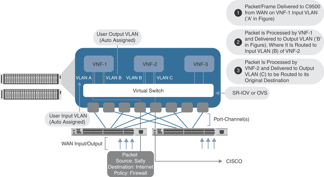
Figure 11-53 Detailed Packet Walkthrough
Just as in the case of the single service node, both control and data policies can be used for the service insertion. The same differences between data and control policies are true for a multinode service chain.
Service Chaining and the Public Cloud
The positioning of Cisco Cloud onRamp for Colocation clusters within colocations is mainly influenced by the following factors:
Amount of available bandwidth to accommodate inbound traffic
Geographic proximity to the source of transmission to minimize backhaul latency
Availability of cross-connects with public cloud providers
Availability of power, cooling, space, and so on
Infrastructure as a Service
Considering the factors in the preceding list, it is feasible to provision Cisco Cloud onRamp for Colocation within the transit path of traffic destined to IaaS resources. There are two 438options to consider when utilizing this type of deployment, though both yield the same result. The first is via direct connection to the cloud provider. Amazon AWS refers to this service as DirectConnect, while Microsoft Azure refers to the service as ExpressRoute. In either case, a physical connection is made between your Cisco Cloud onRamp for Colocation cluster and your resources within the cloud service provider. The second option is via legacy VPN. With this option, a VPN is built between your Cisco Cloud onRamp for Colocation cluster and the cloud service provider. In both instances, the cloud provider will use BGP to peer with Cloud onRamp for Colocation VNF elements to advertise appropriate prefixes. These prefixes are then propagated throughout the WAN or SD-WAN fabric.
Figure 11-54 shows how Cloud onRamp for Colocation can be integrated with other features, such as Cloud onRamp for IaaS (discussed previously). Here, Cloud onRamp for IaaS is used to build automated connectivity into the IaaS cloud while Cloud onRamp for Colocation is used to optimally connect end users to this integration point.
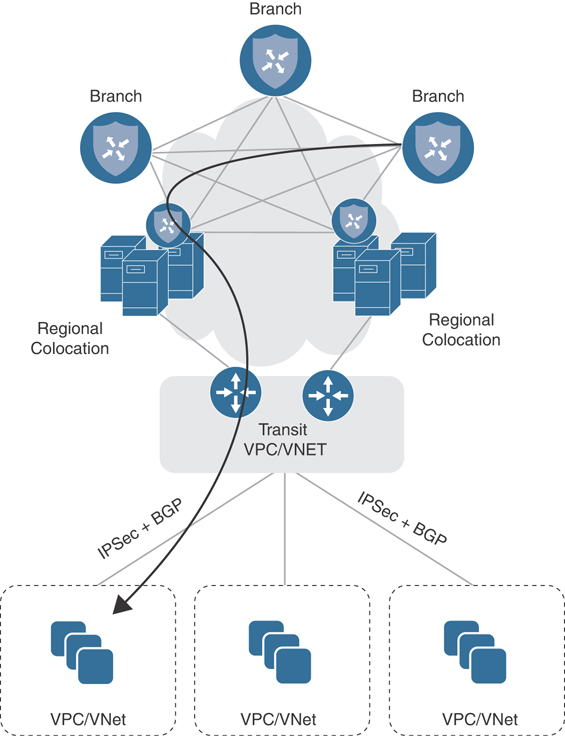
Figure 11-54 Infrastructure as a Service via Colocation
Service chaining for IaaS resources happens in much the same way as with any other service chainable resources. Traffic of interest will be directed to the nearest colocation facility, where it will be processed by Cloud onRamp for Colocation service chains and forwarded to the IaaS provider. If you will recall, Cisco SD-WAN has the capability of extending the SD-WAN fabric to the AWS/Azure cloud (a feature known as Cloud onRamp for IaaS). Though logically this solution seems ideal, the advantage that Cisco Cloud onRamp for Colocation brings to the table is one of reduced latency and optimization. With Cloud onRamp for Colocation, remote sites do not need to transit the Internet (and be subjected to potential latency issues). Instead, IaaS-bound traffic will move to the nearest colocation facility, where it will be processed by a service chain and forwarded on a high-speed backbone link to the IaaS provider, thus minimizing latency and guaranteeing a high-quality experience for the end user.
Software as a Service
SaaS resources, by nature, present a unique challenge to network architecture since the only way to reach these resources is via the Internet. Distributed Internet access (as with SD-WAN) has solved this problem by allowing direct access to these resources from the branch location. However, again, we are confronted with the issue of how to optimize and secure this traffic, without sacrificing the distributed architecture that provides a high-quality experience. Cisco SD-WAN, coupled with Cloud onRamp for Colocation, provides a two-pronged solution to this dilemma.
Ideally, Cloud onRamp for Colocation clusters will be placed in a colocation (or colocations) that has direct connectivity to the SaaS provider’s resources. Given this advantage, we know that the object of the game will be to get our user traffic to the nearest colocation as quickly and efficiently as possible to capitalize on the colocation’s high-speed transport into the SaaS provider’s cloud. To accomplish this, Cisco SD-WAN offers the Cloud onRamp for SaaS feature. This feature utilizes HTTP probing to identify which circuits within the organization offer the least amount of loss and latency to reach a given SaaS application. When this feature is enabled, remote sites will begin to probe SaaS applications via their locally attached Internet 439circuit. In addition, probes can also be sent through colocations. In theory, Cloud onRamp for Colocation–enabled locations will have the best loss and latency into the provider’s cloud and, hence, be chosen as the primary path for reaching the application. In the event of loss or latency within the colocation, one of two outcomes is possible: the traffic will be diverted to the “next best” performing colocation or it will utilize the locally attached Internet circuit, as shown in Figure 11-55.
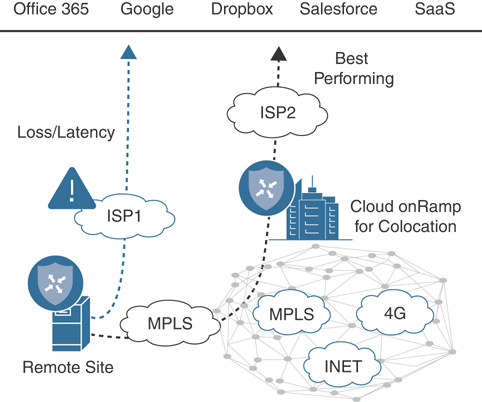
Figure 11-55 Infrastructure as a Service via Colocation
Redundancy and High Availability
High availability and redundancy for service chains are achieved both by provisioning two identical service chains (on separate CSPs within the same colocation) and through the use of multiple colocation facilities hosting the same set of services. In such a case, chassis redundancy is provided through the use of two or more CSPs in the Cisco Cloud onRamp for Colocation cluster. Service chain redundancy is provided either through identical service chains spread across multiple chassis or multiple colocations.
The Cisco Cloud onRamp for Colocation solution monitors each service chain element for uptime and throughput. Upon failure, the device will be rebooted automatically. It is assumed, however, that individual service chain elements also maintain either Active/Active or Active/Standby failover session state. In essence, the automatic reboot should trigger the element to “fail over” to its identical device residing on the second chassis.
Service Chain Design Best Practices
An enterprise would typically go through the following stages while designing its service chains for Cloud onRamp for Colocation:
Identify virtual network functions (VNFs).
Design service chains.
Design the Cloud onRamp for Colocation clusters(s).
As an example, the connection patterns emerge from an analysis of a typical customer network, as shown in Figure 11-56.
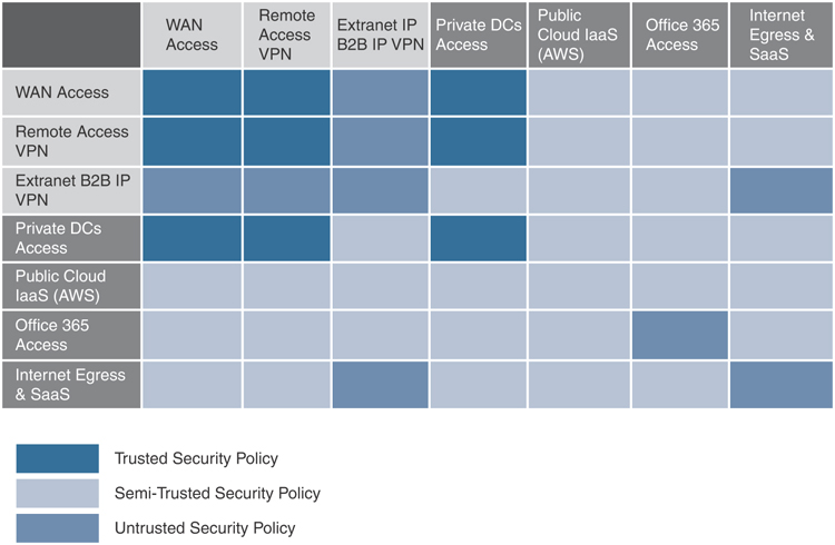
Figure 11-56 Source and Destination Matrix
Based on this information, service-chaining policies can be derived. The table in the figure shows which groups cannot interact with each other (medium blue), which groups can interact but with certain controls (light blue), and which groups can interact without additional services (dark blue). Knowing this information will help determine the type of VNFs needed. For example, when creating a service chain for traffic coming from your employees, you may require fewer firewalls, as the source of such traffic is considered to be trusted.
Cisco Cloud onRamp for Colocation supports both Cisco VNFs and third-party VNFs. Based on your traffic patterns and volume, select the VNF that suits your need best.
Consider the following when selecting VNFs and their placement for your service chains:
SR-IOV versus DPDK: Your service chain design depends on the VNFs you have identified and their support of each of these traffic forwarding modes.
High availability (HA).
Port channeling.
Next, evaluate your compute needs. By default, a cluster must include two CSP 5444 appliances along with two Catalyst 9500 series 40-port switches. This combination provides high-throughput and ample compute capability for most applications (44 CPU cores, 192GB RAM, 5TB hard disk space). Each individual cluster is capable of expanding to eight CSP 5444 appliances, however. Bear in mind that additional CSPs will reduce the number of switch ports available for integrating physical network appliances within your service chains.
Configuration and Management
The entire Cisco Cloud onRamp for Colocation architecture utilizes the same dashboard as the Cisco SD-WAN solution. Hence, all provisioning, troubleshooting, monitoring, and configuration are done within the workflows of vManage.
In this section, we will briefly show how to create a cluster, followed by a simple data policy, to set up a typical service chain.
Cluster Creation
First, verify vManage version via the Help > About screen, as shown in Figure 11-57. At a minimum, Cloud onRamp for Colocation requires version 19.1 of vManage.
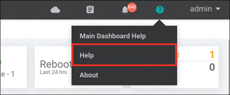
Figure 11-57 vManage Help
Ensure that CSP and C9K device licenses exist within the Configuration > Devices screen on vManage. If not, ensure that valid licenses exist within the appropriate Smart Account for this cluster. These device licenses can then be manually downloaded and imported into vManage or automatically downloaded from the Smart Account (via the Configuration > Devices screen).
From the Configuration menu within vManage, choose Cloud onRamp for Colocation, as shown in Figure 11-58.
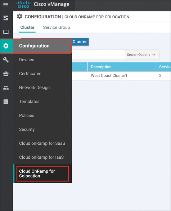
Figure 11-58 vManage Configuration
Before proceeding, ensure that the cluster is correctly cabled. Cloud onRamp for Colocation is designed to be turnkey and prescriptive. Hence, the cluster must be cabled in a prescriptive manner. A cabling guide can be found in the Cloud onRamp for Colocation solution guide on the Cisco documentation website.
Once the cluster is physically cabled and powered on, click the Configure and Provision Cluster button. Enter a name, site ID, location, and description for your cluster, as shown in Figure 11-59. With the exception of Site ID, other values are recommended to be unique.
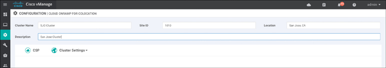
Figure 11-59 Configure and Provision Cluster
Identify the appropriate switches and CSPs for this cluster by clicking the Switch and CSP icons in the middle of the screen. Provide a name, select a serial number, and click the Save button, as shown in Figure 11-60.
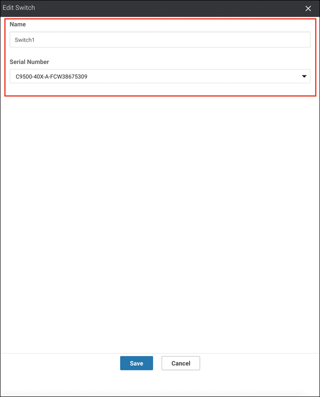
Figure 11-60 CSP and Switch Allocation
Set credentials for this cluster by clicking the Credentials button. By default, CSPs and C9Ks will ship with well-known passwords. It is best practice to set a new, complex password for these devices within this workflow. At a minimum, you should reset the Admin account password, as shown in Figure 11-61, though you may optionally create a new user.
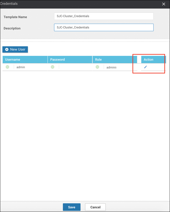
Figure 11-61 Cluster Credentials
Note
Cluster credentials provide command-line access to the CSP and C9K devices. In most circumstances, CLI access to these devices is not required for cluster provisioning and management.
When finished, click the Save button.
Next, specify resource pool settings by clicking the Resource Pool button. These settings allow vManage to stitch together service chain elements as well as allow those service chain elements to boot up with basic configuration parameters for bootstrap purposes (for example, these settings would allow a Firepower Threat Defense virtual firewall to automatically contact Firepower Management Center as soon as it is booted and without user intervention), as shown in Figure 11-62. These values will be unique to your environment, and some are oftentimes provided by the colocation provider. Click the Save button when finished.
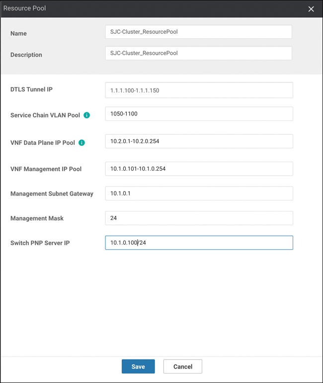
Figure 11-62 Cluster Resources
DTLS Tunnel IP: Analogous to System IP in Cisco SD-WAN nomenclature and only used when a VNF joins the SD-WAN fabric.
Service-chain VLAN Pool: Pool of VLANs that vManage will use to stitch VNFs together from a Layer 2 perspective.
VNF Data Plane IP Pool: Pool of IP addresses that vManage will use to stitch VNFs together from a Layer 3 perspective.
VNF Management IP Pool: Pool of IP addresses that vManage will use to automatically assign management addresses to the management interface of a booting VNF (where applicable).
Management Gateway Prefix: Default gateway for management subnet.
Management Mask: Subnet mask for management subnet.
Switch PNP Server IP: Auto-populated from Management IP Pool but can be manually specified, if desired. This setting identifies the IP address that Colo Configuration Manager will use to communicate directly with the switches. You must configure the address shown in this field as the DHCP Option 43 parameter in your management subnet DHCP server.
Note
Because switches do not join the SD-WAN fabric, they have no way of directly communicating with vManage for provisioning updates. Colo Configuration Manager, or CCM, is a component that automatically spawns with cluster creation and is used to proxy-switch configuration from vManage. It does not require intervention from the administrator for provisioning, managing, or monitoring purposes and should only be accessed under Cisco TAC supervision.
The cluster is now ready to be provisioned. As a final (optional) step, consider adding an NTP and syslog server to this cluster by clicking the Cluster Settings button. Because Cisco SD-WAN relies heavily on certificate authentication, accurate timekeeping is paramount. Hence, an NTP server is strongly recommended. When finished, click the Save button.
Activate the new cluster by clicking the ellipsis (far right side of screen) and choosing Activate. The following screen should appear. To preview the configuration that will be provisioned, click on each of the CSPs in the left pane. When ready, click the Configure Devices button, as shown in Figure 11-63.
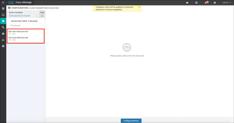
Figure 11-63 Cluster Activation
Note
Although four devices are being provisioned (at a minimum), this task will prompt the user to confirm configuration on only three devices (two CSPs and one Colo Configuration Manager).
Cluster activation can take up to 45 minutes. You can review the status of activation via the workflow screen that appears after clicking the Configure Devices button in the previous step. Alternatively, you can revisit this screen via the Task menu in the upper-right corner of vManage.
As previously discussed, switches do not directly attach to the SD-WAN fabric and, hence, require a local resource for proxy configuration from vManage. In the preceding steps, an IP address was defined for Colo Configuration Manager. The Catalyst 9500 switches, upon bootup, will automatically begin searching for this local resource as part of their bootstrap (PNP) process. In the case shown in Figure 11-64, the switches will learn of CCM via DHCP Option 43. You must configure the Management subnet DHCP server with the appropriate Option 43 information. In Cisco IOS-XE, review the following example. The CCM IP address defined in Figure 11-63 and in Figure 11-64 is 10.1.0.100. Input your values where appropriate.
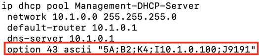
Figure 11-64 DHCP Server Configuration
Note
The ASCII information specified in the Option 43 statement specifies that the switches are to utilize HTTP/S as a transport protocol on port 9191. It is recommended not to alter these values, however. Simply replacing the preceding example’s IP address (10.1.0.100) with your cluster CCM address is all that is required.
Approximately 10 minutes after cluster activation, you might notice that the task output has stopped. This is likely due to the Catalyst switches not contacting the newly created CCM. In such a case, simply reboot the switches to force them to obtain new IP addressing information with DHCP Option 43. Your cluster should then move to ACTIVE state after a few additional minutes.
Note
It is entirely normal for the Catalyst switches to reboot periodically during the provisioning process as the virtual switching system is initialized and inter-chassis port channels are created.
Image Repository
Once the cluster is up and operational, you must upload applicable virtual machine images to the vManage Software Repository via Maintenance > Software Repository. Cloud onRamp for Colocation uses a KVM-based hypervisor. As such, QCOW2 images are the only supported disk image files. To upload a premade package for use within service chains, click the Virtual Images tab, followed by the Upload Virtual Image button.
Where necessary, a custom package can also be created to provide complete flexibility in which devices can be utilized within service chains. Click the Add Custom VNF Package button. Here, you can specify many package parameters (most notably, the Day0 configuration that the device should boot up with) along with uploading your QCOW2 image, as shown in Figure 11-65. When finished, click the Save button.
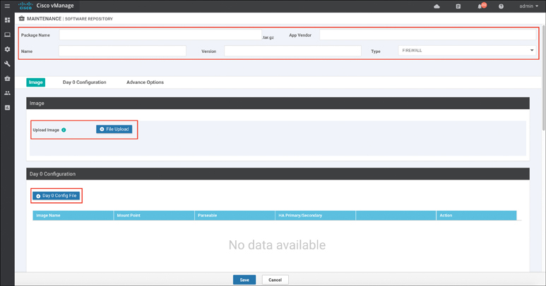
Figure 11-65 Custom VNF Package
Service Chain Creation
The next step in Cloud onRamp for Colocation administration is to define a new data policy. This step instructs remote routers to utilize the service chain that will be built in the proceeding steps. From the Configuration > Policies menu, click the button Add Policy (or, alternatively, you may edit an existing policy). Identify the Match criteria in the first screen (in this case, a Protected-Applications list was created). Click the Next button to navigate to the Configure Traffic Rules section, as shown in Figure 11-66. Click the button to add a new traffic data policy.
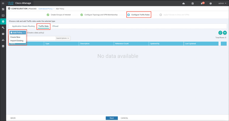
Figure 11-66 Traffic Data Policy
Click the Sequence Type button and select Service-Chaining. Click the Sequence Rule button to construct the policy. In the example shown in Figure 11-67, traffic matching the Protected-Applications list will be subjected to service chaining using the device advertising the Firewall service located at TLOC IP address 1.2.1.1.
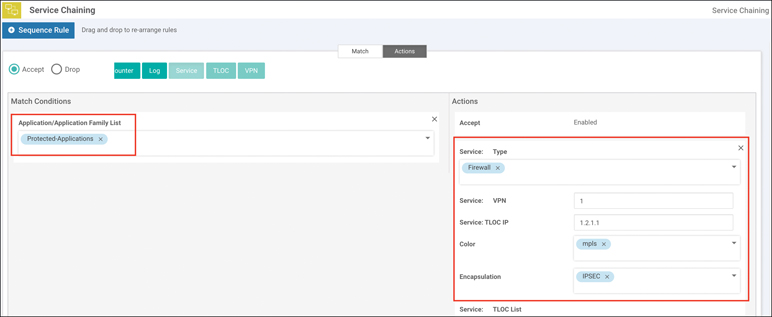
Figure 11-67 Source and Destination Matrix
Save the policy sequence and proceed to the Apply Policies to Sites and VPNs section. Apply the new policy to the SD-WAN routers at the remote sites (this may require you to construct VPN and site lists). In addition, choose which VPN this policy is going to be applied to, as shown in Figure 11-68.
Figure 11-68 Policy Application
Next, a VPN configuration feature template for the colocation router (where the firewall is connected) needs to be created. This template will specify the service node IP address that corresponds to the Firewall label used in the data policy, as shown in Figure 11-69.
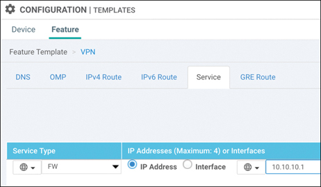
Figure 11-69 OMP Service Advertisement
Next, provision the service chain on the Cloud onRamp for Colocation cluster from within the Cloud onRamp for Colocation > Service Group page. This step assumes that the cluster also hosts the Colocation Edge router that will be advertising the service configured in the preceding step (though this could also be a separate physical box or a traditional IOS-XE CSR, if desired). Hence, you might need to complete this step and revisit the previous steps in order to ensure that the Colocation Edge router is properly advertising the Firewall service.
From the Configuration > Cloud onRamp for Colocation menu, click the Service Groups tab. In Figure 11-70, as part of the Add Service Group workflow, you are prompted to enter ingress and egress VLANs (10 and 20, respectively).
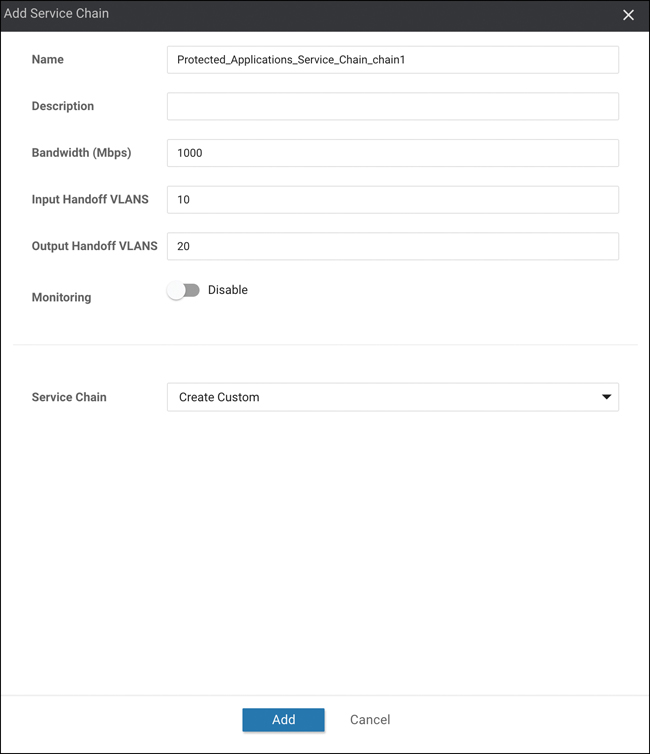
Figure 11-70 Add Service Chain
After clicking Add, you will be prompted to build the service chain. From the screen in Figure 11-71, click and drag each service chain element from the left pane to the right pane (assuming the Custom chain option was selected in the previous workflow screen).
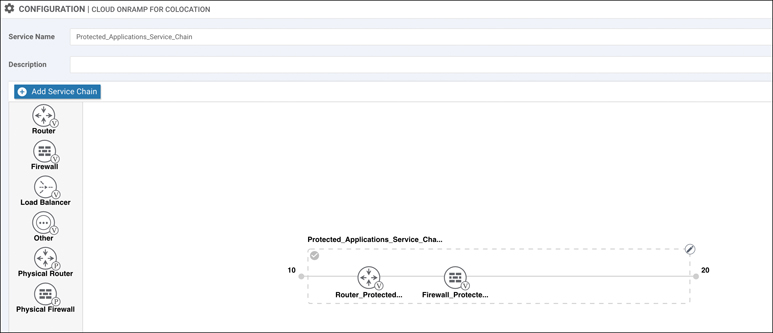
Figure 11-71 Service Chain Creation
Click each of the service chain elements to configure their parameters as appropriate. As discussed previously, some variables within this screen (see Figure 11-72) will be provided by the customer, and others will be pulled from the Cluster Resources configuration pools created in the cluster creation section.
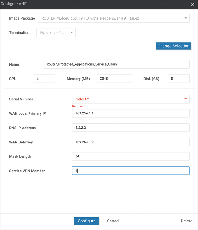
Figure 11-72 VNF Definition
Once complete, click the ellipsis to the right of the new service chain and choose the Attach Cluster option. The configuration established from Figure 11-72 now accomplishes the following:
Establishes a Colocation Edge router to join the colocation to the SD-WAN fabric
Provisions a firewall as the second element of the service chain
Configures the Colocation Edge router to advertise the existence of the firewall through OMP service route announcements
Configures a data policy to force remote site routers to seek out a colocation offering firewall services with which to forward traffic in the “Protected Applications” list
Monitoring
Service chain and cluster status can be viewed via the Colocation Clusters tab of the Monitoring > Network menu, as shown in Figure 11-73. Click the cluster name to view health and performance statistics.
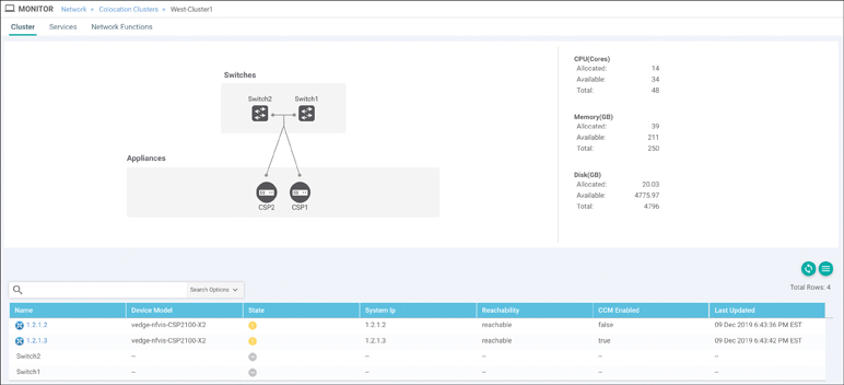
Figure 11-73 Colocation Cluster
From the screen in Figure 11-73, you can view CSP health by clicking the CSP in the lower pane. Service chain health and status can be viewed by clicking the Services tab. You can view the Services screen as a list or graphical representation using the Table | Diagram option, as shown in Figure 11-74. In the Diagram view, hovering over the service chain element presents the user with information specific to the VNF, as shown in Figure 11-75.
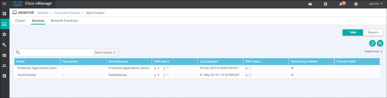
Figure 11-74 Service Chain Status
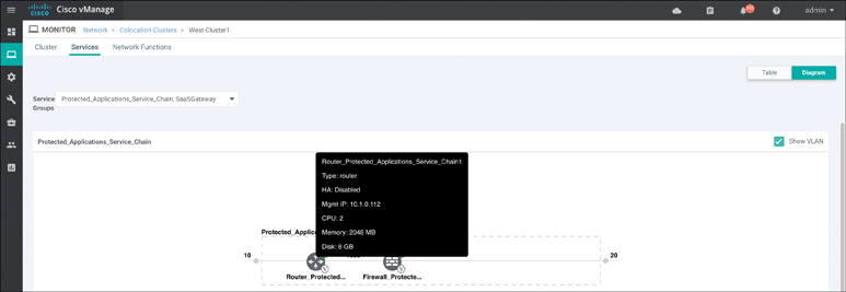
Figure 11-75 Service Chain Status (Diagram View)
You can review individual VNF health via the Network Functions tab in the upper-left corner of this screen. You can view metrics such as CPU, Hard Disk, and Network I/O by clicking the respective tabs in the left pane, as shown in Figure 11-76.
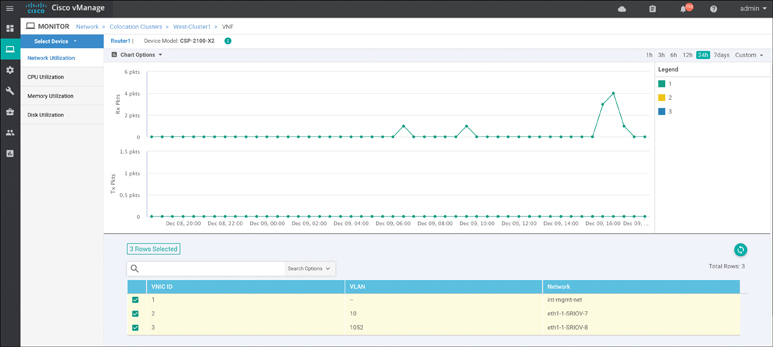
Figure 11-76 VNF Health
Summary
This chapter covered all aspects of Cisco SD-WAN Cloud onRamp, including onRamp for SaaS, IaaS, and Colocation. With onRamp for SaaS, on one hand, the Cisco SD-WAN fabric improves branch-office user experience by using the best-performing network path, increasing application resiliency, and providing path and performance visibility. OnRamp for IaaS, on the other hand, extends the SD-WAN fabric into public cloud instances and provides all the benefits of Cisco SD-WAN directly to the front doorsteps of cloud workloads. Finally, Cloud onRamp for Colocation allows for distributed security enforcement, a scalable architecture through the use of CSP and VNFs, and performance agility by strategic placement of colocation access points.
Review All Key Topics
Review the most important topics in the chapter, noted with the Key Topic icon in the outer margin of the page. Table 11-1 lists these key topics and the page numbers on which each is found.
Table 11-1 Key Topics
Key Topic Element |
Description |
Page |
|---|---|---|
Paragraph |
Direct cloud access use case |
395 |
Paragraph |
Cloud onRamp for IaaS concept |
413 |
Paragraph |
Cloud onRamp for Colocation concept |
429 |
Section |
Service Chaining for Single Service Node |
434 |
Section |
Service Chaining for Multiple Service Nodes |
436 |
Define Key Terms
Define the following key terms from this chapter and check your answers in the glossary:
Chapter Review Questions
1. Cisco Cloud onRamp for SaaS requires a Cisco SD-WAN Edge router to be placed in the SaaS cloud.
True
False
2. What are the three Cloud onRamp for SaaS site types?
Gateway site
DIA site
Local site
Client site
Hub site
3. Cloud onRamp for SaaS supports dual Internet and MPLS transport sites.
True
False
4. Cloud onRamp for SaaS DPI does not redirect the initial application flow after detection.
True
False
5. Which two real-time outputs provide information about Cloud onRamp for SaaS?
CloudExpress Applications
CloudExpress Paths
CloudExpress Gateway Exits
CloudExpress Local Paths
CloudExpress Statistics
6. Which three things is a WAN Edge Cloud router provisioned with automatically?
Management VPN
Transport VPN
BGP AS
SNMP ID
Service VPN
7. How many Cisco SD-WAN WAN Edge Cloud routers are provisioned in a single transit VPC or VNET during the Cloud onRamp for IaaS process?
It depends on the scale of the network.
Two
Four
Eight
8. When logging in to an AWS cloud instance during the Cloud onRamp for IaaS process, both IAM role and API key methods are supported.
True
False
9. When you monitor Cisco Cloud onRamp for IaaS, which of the following can you view? (Select three.)
The connectivity state of each host VPC
The concurrent sessions going through the transit VPC
The state of the transit VPC
Detailed traffic statistics for the IPsec VPN connections between the transit VPC and each host VPC
10. Cloud onRamp for Colocation includes which of the following components? (Select all that apply.)
Cisco CSP
Cisco Catalyst 9K
Cisco WAN Edge Cloud router
Cisco Identity Services Engine
11. Cisco Cloud onRamp for Colocation supports which two types of service insertion?
Control policy
Local policy
Data policy
CLI policy
OMP policy