Chapter 11
Basic Aeronautical Knowledge
In This Chapter
 Deciding whether to take flying lessons
 Getting a handle on the fundamental science of aviation
 Exploring fixed-wing and rotary-wing aircraft
 Using two sample flight lesson plans
You can ride a bike without a lot of detailed training, but the same can’t be said for flying an aircraft; you have to be familiar with all sorts of aircraft parts and instruments and know how outside conditions and your actions will affect how your craft flies. In this chapter, we look at the basic aeronautical knowledge that you need for the various flight aptitude tests. Note that we cover only the minimum knowledge you need to successfully complete the tests; after you’re selected for a military flight training program, that program will instruct you in much greater detail in each of these subjects.
We first consider the advantages and disadvantages of taking flying lessons before you take a military flight aptitude test. We then explore both fixed- and rotary-wing aircraft to give you a conceptual knowledge of each. We cover the correlation between the various flight instruments and end the chapter with two sample flight lesson plans.
Getting a Flying Start: Debating Pre-Test Flying Lessons
The question, “Should I take flying lessons before I take the test?” comes up more often — and sparks a far greater number of differing opinions — than any other subject in this book.
On the pro side of the argument, anything that gives you an edge on the test has to be a good thing, right? Flying lessons not only teach you the basics of such topics as aviation fundamentals (including lift, drag, weight, and power), aircraft parts and control surfaces, and instruments and controls but also give you time in the sky.
On the other hand, many feel that the military is seeking only a potential skill level and that, after you’re selected, you’ll receive all the required flight training you’ll ever need — and perhaps a bit more. After all, the military’s goal for the test is to find those who are potentially best suited for a career in military aviation, not those who are already talented aviators. Some observers will even tell you that previous flight training only ensures that you’ve developed bad habits that a military instructor pilot will have to correct.
Although this last argument has some validity, we strongly believe that a minimal amount of flight training can provide you with enough conceptual knowledge to give you an edge on the flight aptitiude test. We’re not talking about hours and hours in the cockpit; a minimum of two to three hours of flight experience and the associated ground schooling can give you a leg up (though we recommend getting a private pilot’s license if possible). If you’re determined to pass the exam (and we can guess you are because you’re reading this book), even a slight edge may be well worth the time and the relatively small amount of money you spend for flying lessons at a local airport. In fact, the U.S. Air Force actually increases (on a graduated scale) your chance of being selected for pilot training for up to 200 hours of flight time.
Understanding the Basic Science of Flight
Although people often marvel at airplanes as feats of technology, few have stopped to think about just how the plane gets in the air. But as a military aviator, those scientific concepts are vital parts of your training, and your flight aptitude test is sure to quiz you on them. The following sections give you the skinny on some of the critical scientific principles for flying.
For additional coverage, we recommend Aerodynamics for Naval Aviators by H. H. Hurt, Jr. (Skyhorse Publishing) and either Rotary Wing Flight by the FAA (Aviation Supplies and Academics, Inc.) or the Army field manual called Fundamentals of Flight (FM 1-203).
Appreciating the atmosphere
The aircraft you pilot someday will penetrate the atmosphere somewhat like a boat paddle going through the water, so you want to know a little more about the makeup of the wild blue yonder than just “It’s made of air and stuff.” The earth’s atmosphere is comprised of various elements (Chapter 9 covers the more-exact composition); as a whole, it affects your aircraft and its performance. But aviators are primarily concerned with the oxygen in the atmosphere and the effect that element has on their bodies, as well as how temperature and humidity affect aircraft performance. Just a little more than 20 percent of the atmosphere is made up of oxygen; this element is relatively heavier than most other gaseous elements in the atmosphere, so you find more of it below 30,000 feet. The higher you fly, the less oxygen pressure you have available, and that’s why pilots wear oxygen masks above a certain altitude.
During the test, you can expect questions about the atmosphere and how it relates to the aviation world. Here’s an example of an atmosphere-type question you may encounter:
 The most accurate description of earth’s atmosphere is that it is made up of
(A) 78 percent oxygen, 19 percent nitrogen, and 2 percent carbon dioxide, with trace amounts of water vapor and dust particles.
(B) 3 percent water vapor, 78 percent ozone, and 20 percent nitrogen.
(C) 20 percent oxygen, 77 percent hydrogen, 3 percent carbon dioxide, and some water vapor.
(D) 21 percent oxygen, 78 percent nitrogen, .03 percent carbon dioxide, trace amounts of rare gases, water vapor, and some dust particles.
(E) 77 percent oxygen, 21 percent hydrogen, and 2 percent carbon dioxide, with trace amounts of nitrogen, water vapor, and dust particles.
The correct answer is Choice (D).
Focusing on the four forces acting on an aircraft
Four forces are necessary for an aircraft to fly, and understanding them helps you recognize the limitations you must overcome to successfully challenge the bonds of earth. Here’s a basic description of each; you can see the forces in Figure 11-1:
 Lift: Lift is the upward force vector resulting from air movement along both the upper and lower portions of the wing. (We describe this vector in more detail in the later section “Lifting off with the airfoil.”)
 Drag: Drag is the air resistance that slows down the forward movement of an aircraft. You encounter two types of drag: induced, which is the drag that results from the wing’s developing lift, and parasite, which is the drag associated with the resistance to forward movement.
 Weight: Weight is the downward force resulting from the gravitational pull of the earth.
 Power: Power, or thrust, is the force that enables an aircraft to move forward though the air.

Illustration by Wiley, Composition Services Graphics
Figure 11-1: The interaction of these four forces allows the aircraft to fly.
Your test will feature questions that both directly and indirectly relate to the four forces on an aircraft in a given situation. An example of one such question may include the following:
 The four forces that act on an aircraft in flight are
(A) Lift, weight, thrust, and drag
(B) Lift, mass, propulsion, and resistance
(C) Aerodynamics, mass, propulsion, and drag
(D) Lift magnitude, mass, thrust, and drag
(E) Roll, pitch, yaw, and magnitude
The correct answer is Choice (A).
Knowing Newton’s three laws of motion
Sir Isaac Newton’s laws of motion are basic scientific principles that explain how flight is possible. Without them, no flight.
 Newton’s First Law of Motion: Unless acted upon by an outside force, a body at rest tends to remain at rest, and a body in motion tends to remain in motion.
 Newton’s Second Law of Motion: An object changes velocity if it’s pushed or pulled on. When an outside force acts on an object, the object’s acceleration is directly proportional to the applied force and inversely proportional to the mass of the object. This law derives the formula of F = ma, where F is the force acting on an object, m is the object’s mass, and a is the object’s acceleration.
 Newton’s Third Law of Motion: For every action, there is an equal and opposite reaction.
The flight aptitude test will test your ability to apply Newton’s laws. An example of a type of question on this topic includes the following:
 A body at rest tends to
(A) Accelerate at a constant velocity
(B) Remain in motion
(C) Fall to the ground
(D) Remain at rest
(E) Reach escape velocity
The correct answer is Choice (D).
Lifting off with the airfoil
The airfoil — the structure commonly known as the wing — is what allows an aircraft to fly (see Figure 11-2). Basically, the airfoils travel through the air at a given speed to enable lift to occur.

Illustration by Precision Graphics
Figure: 11-2: An airfoil with relative wind travel.
When an airfoil travels through the air, the air separates over and under the wing. Both streams of air must divide at point A and reach point B at the same time. As you can see in Figure 11-2, the upper curvature of the wing is greater than the lower curvature. Therefore, the air traveling over the top of the wing must move at a faster speed than the air traveling under the lower portion to reach point B at the same time.
Bernoulli’s principle states that as the velocity of a fluid (in this case, air) increases, the pressure exerted by that fluid decreases. Simply put, the faster air traveling over the top of the airfoil causes a decrease in pressure, which results in a lifting force. That’s why a wing needs forward motion to gain lift. Without enough forward motion (airspeed), lift is reduced, and the airplane won’t fly.
But speed isn’t the only vital component of lift. The angle of attack is a reference line that represents the angle of the chord line (the line from the leading edge of an airfoil to the trailing edge) in relation to the forward airflow against the wing. As you increase the angle of attack, lift increases to a point (usually around 17 degrees) called the critical angle of attack; going past that point disturbs the airflow, and you lose lift (also known as experiencing a stall of the wing).
Bernoulli’s principle and wing lift are critical in aviation. Here’s how the exam may test you on this subject:
 Most of the lift on an aircraft’s wings is because of
(A) A decrease in pressure on the bottom side of the wing
(B) A decrease in pressure on the upper side of the wing
(C) A vacuum created under the wing
(D) An increase in pressure on the upper side of the wing
(E) None of the above
The correct answer is Choice (B).
Figuring out the Operation of Fixed-Wing Aircraft
A fixed-wing aircraft is characterized by rigidly or semirigidly attached wings that gain lift by the forward movement of the aircraft in relation to relative wind (see Figure 11-3). The following sections let you in on some of the important aspects of fixed-wing aircraft that you want to know for the aptitude test.
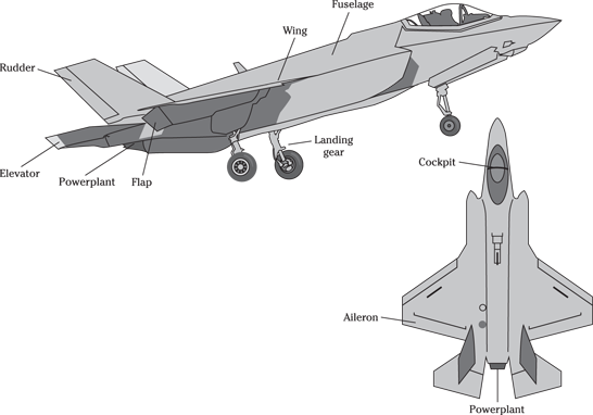
Illustration by Precision Graphics
Figure 11-3: Major parts of a standard fixed-wing airplane.
Addressing aircraft axes of movement
Whenever an aircraft changes its position in flight, movement is defined as a rotation around one of three axes of flight. These axes of movement are imaginary lines that run through the aircraft’s center of gravity (a point where the force of gravity is centered on the aircraft):
 Longitudinal: The imaginary line from the front to the rear of the aircraft is the longitudinal axis, and it’s characterized by a rolling motion (that’s why it’s sometimes called the roll axis).
 Lateral: The imaginary line from the aircraft’s center of gravity to the opposite wingtip center point is called the lateral axis or the pitch axis, and it involves a pitching motion.
 Vertical: The imaginary line that is vertical through the aircraft’s center of gravity is the vertical axis or yaw axis, and movements around it are yawing motions.
All angles intersect at a relative 90-degree angle, and movements along the three axes are controlled by changes in various surface structures (see Figure 11-4).
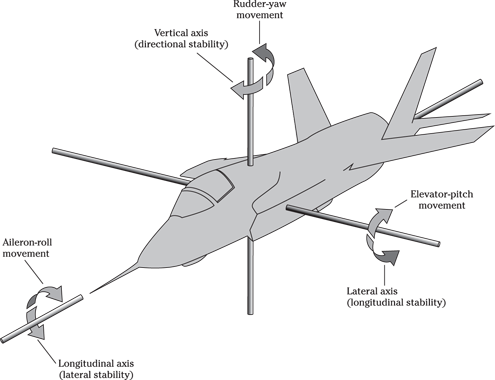
Illustration by Precision Graphics
Figure 11-4: The three axes of flight.
The flight aptitude test will contain conceptual and situational questions about the three axes of flight, such as the following:
 The three axes around which flight movement occurs are
(A) Horizontal, vertical, and lateral
(B) Latitude, longitude, and vector
(C) Lateral, longitude, and vector
(D) Lateral, longitudinal, and perpendicular
(E) Roll, pitch, and yaw
The correct answer is Choice (E).
Whizzing through wing types and placement
Although you don’t need to worry about the aeronautical design and efficiencies of various wing shapes, you should at least be aware of the different wing shapes and placements, each of which has distinct advantages and disadvantages. (Check out the wing designs in Figure 11-5; you don’t need to worry about the specific pros and cons of each for the test.)
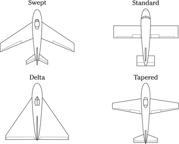
Illustration by Precision Graphics
Figure 11-5: A variety of wing designs (swept, standard, delta, and tapered).
Looking at landing gear
Landing gear is the fuselage attachment that allows the aircraft to absorb the impact upon a positive and sometimes abrupt contact with a landing area. Landing gear can be either fixed or retractable and designed to land on hard or rough surfaces, land, or water. Military aircraft that land on hard surfaces (except helicopters) usually employ retractable landing gear to reduce the negative effects of drag.
Perusing the primary flight controls
Different controls in the crewmember station effectively change the way the different airfoils on an aircraft react with the relative wind. The primary flight controls are the stick-and-rudder controls that change the movement of the rudder, ailerons, and elevators. (Don’t worry, future rotor-heads: We cover rotary wing controls later in this chapter.)
 Pitch: Pitch is controlled by the elevators and changes as a result of pulling the stick, or yoke, fore and aft. If you pull back the yoke or stick, the aft edges of the elevators move up (each in the same direction), forcing the tail of the aircraft down and the nose up and creating pitching, or a rotation around the lateral axis.
 Roll: Roll is controlled by the wing ailerons (small movable sections of the wings, located at the trailing edges, that control roll movements) and changes as a result of pushing the stick, or rotating the yoke, left or right. The ailerons move opposite from one another to gain a rolling motion along the longitudinal axis (as we note earlier, like a paddle in the water). If you turn the stick or yoke left, the aileron on the left wing has its trailing edge pointed upward, pushing the left wing down, and the right wing has its aileron pointed downward, pushing the right wing up. This action results in a left rolling motion.
 Yaw: Pushing your feet against the rudder pedals establishes a yaw motion. If you push the left rudder pedal left, the aft (rear) section of the rudder moves left (forcing the tail right and nose of the aircraft left) and turns the aircraft left around the vertical axis.
To perform a turn or any flight maneuver, you must apply a series of interrelated coordinated applications of these flight controls in what’s called a coordinated turn.
Considering secondary flight controls
Secondary flight controls assist with the primary flight controls during different flight configurations. (Head to the preceding section for info on primary flight controls.) Aircraft secondary flight controls include trim devices and flaps.
 Trim devices are designed to reduce the physical effort and input by the aviator (that’s you) to maintain a stable flight profile.
 Flaps, inboard from the wing ailerons, work in unison and extend during takeoff and landing to increase the camber (outside upper portion) of the wing. When you lower the flaps, you increase the drag on the aircraft and increase lift. Flaps aren’t required at level cruise flight, but they become critical at takeoff and landing, where you want greater lift at a slower speed than normal. This extra lift and drag allows your aircraft to land at much slower speeds and clear obstacles on both takeoff and approach.
Firing up for flight instruments
The early aviators didn’t have much in the way of flight instruments, but today’s pilots have more than a piece of string in the windshield (yes, they actually used that) to give guidance on what their aircraft are doing. The flight instruments tell you how high you are, which way you’re heading, how fast you’re flying, and if you’re in a turn. Trust us, the instruments in the following sections come in handy when you’re flying visually at night and punch into the clouds without warning.
Altimeter
You can determine your altitude based on the atmospheric pressure; the greater the altitude, the less the outside pressure. Your aircraft’s altimeter is an instrument that uses the barometric pressure to accurately tell you your elevation in relation to mean sea level (the average surface level of the sea). To do so, it applies a standard (a constant for comparison); the standard atmospheric condition is 29.92 Hg (inches of mercury).
The altimeter, shown in Figure 11-6, features an elevation dial and a small pressure window (called the Kollsman window) where the barometric pressure is set. Just about every initial aviation communication includes the barometric pressure; by setting this number in the Kollsman window, you can tell your altitude in relation to sea level. If you know how high the surface elevation you’re flying over is, you know your above ground level (AGL) altitude.
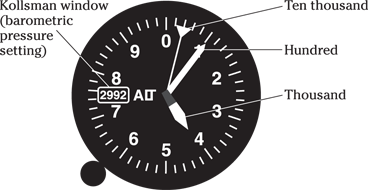
Illustration by Precision Graphics
Figure 11-6: An altimeter.
Say you’re flying in a relatively high-pressure area; approach control has told you the pressure is 30.22. You set the altimeter to reflect the information given to you by air traffic controllers (along with current safety hazards), and you see that your altimeter reads 1,275 feet. Looking at your approach chart or map, you see that the airfield that you’re over has an elevation of 230 feet, so you know you’re 1,045 feet above the ground (that’s your altimeter reading minus the airfield’s elevation).
Attitude indicator
The attitude indicator (see Figure 11-7), also known as the artificial horizon, gives you an aircraft orientation relative to the horizon of the earth. Before each takeoff, you set the attitude indicator to level flight. This instrument, in conjunction with others, can then tell you whether you’re climbing or descending (pitch indication) and whether your wings are in a turning attitude (roll indication). This indicator is one of the primary instruments for nonvisual (inclement weather) flying.
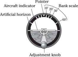
Illustration by Precision Graphics
Figure 11-7: An attitude indicator.
Turn indicators
Turn indicators serve as backups to the attitude indicator (see the preceding section) and utilize gyroscopic inertia (the tendency of a gyroscope wheel to continue rotating in the same plane about the same axis in space). Turn indicators fall into two basic categories, both of which are shown in Figure 11-8.
 A turn-and-slip indicator shows the rate and direction of a turn. The slip portion of the indicator tells you you’re performing a coordinated turn and using all the controls efficiently.
 In a standard turn, with all aerodynamic forces being efficient, you will complete 360 degrees in two minutes.
 A turn coordinator shows the rate of turn and the roll rate (how fast you enter into the turn at a specified bank angle).
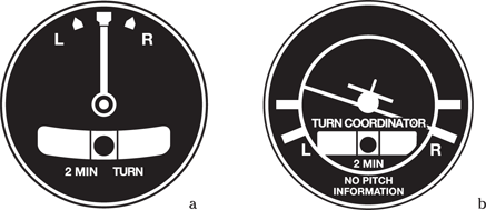
Illustration by Precision Graphics
Figure 11-8: A turn-and-slip indicator (a) and turn coordinator (b).
Heading indicator
The heading indicator, also known by the older term directional gyro, is a mechanical instrument that backs up and serves as an aid to the magnetic compass. The heading indicator (shown in Figure 11-9) stabilizes the readings and allows you to navigate without the fluctuation errors found in the magnetic compass.
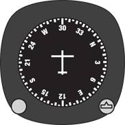
Illustration by Wiley, Composition Services Graphics
Figure 11-9: A heading indicator.
Airspeed indicator and vertical speed indicator
The airspeed indicator (shown in Figure 11-10) detects and displays a differential pressure that adjusts ram airspeed (pitot pressure) for static pressure. Basically, that means that the airspeed indicator tells you vital airspeed rates critical to achieving a desired flight profile (such as a climb, descent, or level). If you look closely at the indicator, you see various colored lines. The white arc represents the stall (minimum) and maximum speeds you can operate at with the flaps extended. The green arc shows the normal airspeed operating range of the aircraft. The yellow arc is the caution range in which you can safely operate the aircraft in smooth, non-turbulent air only. The red line at the upper edge of the yellow arc is the velocity at which the aircraft sustains structural damage, so don’t cross it.
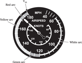
Illustration by Wiley, Composition Services Graphics
Figure 11-10: An airspeed indicator.
The vertical speed indicator (shown in Figure 11-11) tells you whether you’re climbing or descending and at what rate of speed by detecting the rate of change in static air pressure.
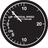
Illustration by Precision Graphics
Figure 11-11: A vertical speed indicator.
Examining engines (piston and turbine)
The modern military utilizes the turbine engine (also known as a powerplant), which is designed to deliver power by exhaust thrust or is geared to a controlled pitch propeller. You can check out a turbine engine in Figure 11-12. Piston engines, like the ones you experience during any pre-test flight training, are commonly used in civilian aviation. (Because you won’t use a piston engine in your military flight training, we don’t feature a cross section figure of one here. See the earlier section “Getting a Flying Start: Debating Pre-Test Flying Lessons” for info on taking lessons.)

Illustration by Wiley, Composition Services Graphics
Figure 11-12: Cross section of a turbine engine.
Putting the instruments and plane setup concepts together
When taking a military flight aptitude test, you need to understand the correlation between the aircraft flight instruments and the relative position of the airframe in 3-D perspective. You must comprehend how the different flight instruments are connected to give you an overall view of the aircraft at a particular point in space.
The test gives you pictures of a situational view of an aircraft, and you must be able to correctly decide what the cockpit instruments will look like for that particular aircraft attitude. Because the gauges may be difficult to read when they’re reduced to fit in the cockpit dashboard in these figures, we also duplicate the gauges in an enlarged view. Following are examples of how the aircraft instruments correlate to the aircraft attitude.
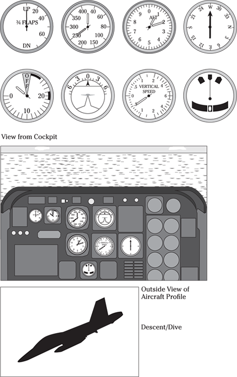
Illustration by Wiley, Composition Services Graphics
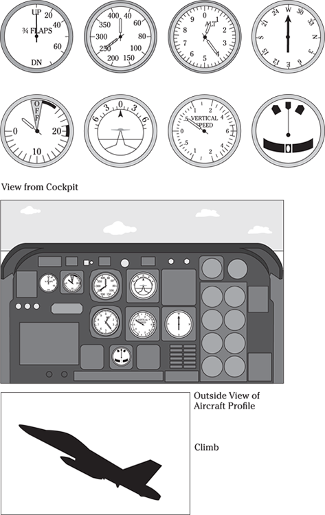
Illustration by Wiley, Composition Services Graphics
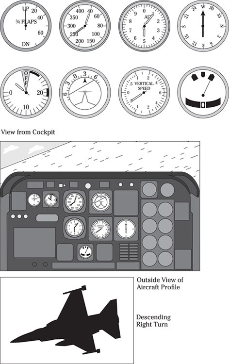
Illustration by Wiley, Composition Services Graphics
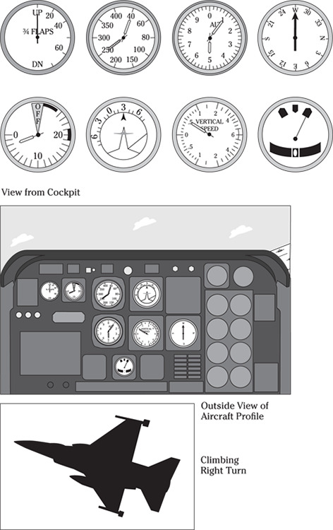
Illustration by Wiley, Composition Services Graphics
 In the figure, which of the four aircraft attitudes pictured is the correct aircraft as depicted by the aircraft instruments?
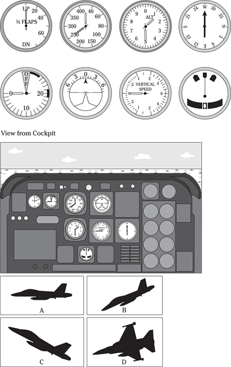
Illustration by Wiley, Composition Services Graphics
(A) Aircraft A
(B) Aircraft B
(C) Aircraft C
(D) Aircraft D
The correct answer is (A).
Reviewing the Components of Rotary-Wing Aircraft
A rotary-wing aircraft, shown in Figure 11-13, is characterized by airfoils or wings that are attached to a hub and rotate to achieve lift. (Although various types of rotary-wing aircraft exist, the only one you need to concern yourself with for the test is the helicopter; that’s the one we discuss here.) Rotary-wing aircraft gain lift and forward momentum by tilting the plane of the rotor disk and changing the direction of lift toward a somewhat forward (or sideways, if desired) direction. This rotating lifting capability allows the aircraft to either hover stationary above a fixed point or to land or take off with minimal forward motion.
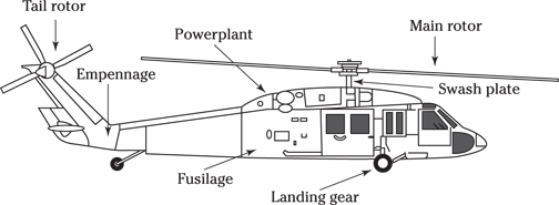
Illustration by Wiley, Composition Services Graphics
Figure 11-13: Key parts of a standard helicopter.
Talking about types of rotor blade systems
Rotor blade systems basically describe the different ways in which the rotor blades are attached to the engine. Three types of rotor blade systems are most commonly in use today:
 Fully articulated: A fully articulated rotor blade system typically has three or more rotor blades. Each rotor blade is attached to the rotor hub independently; through a series of hinges, the blades are allowed to flap and lead/lag independently to overcome the effects of dissymmetry of lift, or the difference in lift between the advancing main rotor blade and the retreating main rotor blade.
 Rigid: A rigid rotor blade system usually refers to a hingeless system with blades that are flexibly attached to the hub.
 Semirigid: A semirigid rotor blade system is a two-bladed system that is rigidly attached to the rotor hub and allows for flapping and feathering. The two blades flap rather like a seesaw: As one flaps down, the other flaps up.
Landing gear
Helicopter landing gear consists of either skids or wheels to facilitate movement while taxiing on land. Helicopters are designed to land in unimproved areas — that is, areas without paved runways in good condition — so proper landing gear is vital.
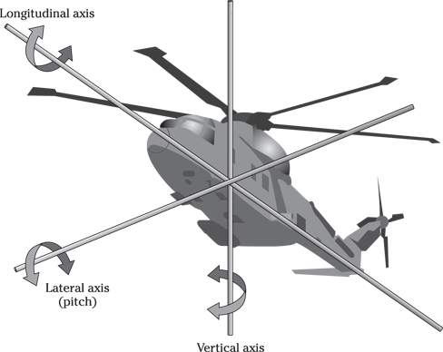
Illustration by Wiley, Composition Services Graphics
Figure 11-14: A helicopter’s three axes of movement through the center of gravity.
Peeking at primary flight controls
In a helicopter, the primary flight controls consist of the cyclic, the collective, and the anti-torque pedals.
 Cyclic control: The cyclic control, which looks much like the stick in a fixed-wing aircraft, tilts the entire rotor disc by changing the pitch angle (that is, the angle of attack) of each rotor blade in cycles from a maximum position to a minimum position during each rotation.
 Collective control: The collective control, located on the left side of the pilot, allows for a simultaneous increase or decrease in pitch of the main rotor blades. This pitch change results in the lifting force of a helicopter. As the pitch increases, you get more lift, but the main rotor system also needs more engine power from the transmission. This increase in power is controlled by a mechanical governor or by a twist-grip throttle control located on the collective handle.
 Anti-torque control: Anti-torque (or the counter main rotor torque) helps prevent the aircraft fuselage from turning as a result of the torque of the overhead spinning main rotor system. Mechanically, the tail rotor is geared to turn faster — usually about three revolutions to each revolution of the main rotor system — and counters this torque to control any yaw movement. By pushing the anti-torque pedals (located where the rudder pedals appear in fixed-wing aircraft), you maintain the ability to move the nose of the aircraft to the left or right as desired.
Note: The discussion of secondary controls for rotary-wing craft is quite murky and complicated, so we don’t open that can of worms here. You won’t be required to know about those controls for the flight aptitude test anyway.
Investigating flight instruments
The helicopter employs basically the same flight instruments as fixed-wing aircraft (see the earlier section “Firing up for flight instruments”), with just a few exceptions. The most important difference is the torque gauge, which informs you how much torque, or engine power, is being applied to the main rotor system. This important indicator gives you critical information regarding available thrust to lift any required payload. Torque is the limiting factor in helicopter carrying capability because of either absolute engine power available or transmission limitations.
Revisiting engines (piston and turbine)
Understanding how the helicopter flies
A helicopter turns its overhead main rotors until it reaches an operational speed determined by the aircraft manufacturer’s design engineers. The tail rotor, which is smaller and sometimes has more blades than the main rotor, rotates more quickly. This tail rotor counters the overhead lateral rotational torque.
You begin to take off by increasing the pitch of the main rotor blade, with the tail rotor automatically increasing its rotational speed. However, you usually have to use the anti-torque pedals to correct a turning tendency as this initial takeoff occurs. At the same time, you have to correct a drifting motion (caused by dissymmetry of lift) by applying a cyclic control movement (left or right, depending on which way the rotor turns). All these corrections require constant power adjustments (unless your aircraft adjusts the power automatically through a governor). Each and every input requires an adjustment to the others; the balancing act of power and inputs is called hovering, and it’s a challenging task.
Basic flight principles
The helicopter hovers either in ground effect (increased lifting efficiency) or out of ground effect depending on power available (which depends on ambient conditions). During a normal takeoff, you apply a forward tilt of the rotor disc to gain forward momentum. At first, the aircraft is in disturbed air and isn’t as efficient as it can be. But as the aircraft begins its forward acceleration, it eventually overcomes the downward rotor wash effect and moves into completely undisturbed air. When this shift happens, you’ll notice a substantial increase in aircraft efficiency, called effective translational lift. If you’ve ever flown in a helicopter and experienced a vibration at the beginning of takeoff and toward the end of an approach, that was effective translational lift.
Cruise flight, ascents, and descents are connected just like hovering, with varying degrees of rotor disc inputs, collective levels, and counteractive anti-torque movements. Because the instruments in helicopters are largely the same as in fixed-wing aircraft, the instrument usage is basically the same as well, with the exception of the torque indicator.
You will be expected to understand the basic flight principles and differences between fixed- and rotary-wing aircraft for the flight aptitude test. An example of a test question over this knowledge may be the following:
 The lift differential that exists between the advancing main rotor blade and the retreating main rotor blade is known as
(A) Coriolis effect
(B) Dissymmetry of lift
(C) Translating tendency
(D) Translational lift
(E) Lift vector
The correct answer is Choice (B).
Helicopter-specific flight principles
Two important, helicopter-specific flight principles are retreating blade stall and autorotation.
 Retreating blade stall occurs when the retreating blade loses speed and increases its angle of attack. As the helicopter flies forward, the rotor’s tip speed approaches the speed of sound. The advancing blade has the forward speed of the aircraft speed plus the rotor turn speed. The retreating blade’s overall effective speed decreases as the aircraft speed increases, to the point where the retreating blade actually stalls and suddenly loses its lift, resulting in a very dangerous condition.
 Autorotation describes the situation where, upon losing engine power, the pilot releases the gear-driven aspect of the rotor blades by immediately reducing the cockpit collective lever and thereby reducing rotor blade pitch. This action allows the blades to freely windmill with the forward upward flow of air through the rotor system. The aircraft begins a (very) rapid rate of descent but builds up or retains inertia in the rotor system to trade off for lift in the final seconds before impact with the ground, as shown in Figure 11-15.
 Autorotation is a timed event, and if you trade the inertia for lift too soon, the aircraft will run out of lift too high above the ground. And if you make the trade too late . . . well, that’s why autorotation timing will be a primary focus of your helicopter training.
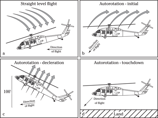
Illustration by Wiley, Composition Services Graphics
Figure 11-15: Airflow during autorotation.
Sample Flight Lesson Plans
If you do decide to take some flying lessons before you take your military flight aptitude test, here are two handy flight lesson plans specifically designed to provide you with the basic information you’ll need to get an advantage on the test. We cover the pros and cons of taking flying lessons in the earlier section “Getting a Flying Start: Debating Pre-Test Flying Lessons.”
If you have no flight experience and plan to do the minimal amount to gain situational awareness, show your flight instructor these lesson plans and a sample of the test you’ll be taking. Get at least two to three hours in the air focusing on the situations that the test will cover. If money is the determining factor, we suggest you take minimal actual flight lessons (in a real airplane), take a formal ground school (you can often find classes at colleges and universities), and use some of the flight simulation software found commercially.
Flight lesson #1
Objectives: To familiarize the potential aviation officer candidate with the basic aerodynamic principles, engine, aircraft systems, and flight instruments. To provide the potential aviation officer candidate with a hands-on knowledge of basic flight maneuvers.
Pre-lesson ground school time: 5 hours. This self-research is designed to give you conceptual knowledge of the aircraft flight principles you’ll be covering.
Pre-flight ground time: 45 minutes. You spend this time before the flight period with a flight instructor, who explains in detail the flight objectives and answers any questions you may have.
Flight time: 1.5 hours.
Post-flight ground time: 30 minutes. You us this period to review the flight with the instructor, who follows up on any of your unanswered questions.
Non-flight content
Newton’s laws
Bernoulli’s principle
Principles of flight
Lift
 Explanation of lift
 Factors effecting lift
Weight
 Load terms and types
 Center of gravity
Drag
 Parasite
 Induced
Thrust
 Powerplant and propeller
 Piston versus turbine
 Propeller thrust development
 Turbine (jet) thrust development
 Controllable pitch propellers
Wing design
Aircraft design
Fuselage
Ailerons
Flaps
 Plain
Plain
 Slotted
 Split
Split
 Fowler
Rudder
Elevators
Flight controls
Flight content
Introduction to takeoff
Straight and level flight
Orientation to flight instruments and power settings
Climbs
Descents
Climbing and descending turns
Stalls
Basic navigation reference
Introduction to landings
Flight lesson #2
Objectives: To give the potential aviation officer candidate a continued grasp of aviation fundamentals to further instruct the candidate on the aircraft system and navigation instruments and how they correlate with pilot maneuver inputs.
Pre-lesson ground school time: 5 hours
Pre-flight ground time: 1.5 hours
Flight time: 1.5 hours
Post-flight ground time: 30 minutes
Non-flight content
Review of lesson #1
Aircraft systems and flight instruments
Navigation instruments
Basic flight principles and flight instruments
Examples of flight instrument displays/aircraft attitude
Flight content
Instrument correlation of aircraft
Takeoff
Climbing and descending turns
Steep turns
Slow flight
Stalls
Introductions to landing
 Before you begin your flight training, be sure your instructor knows your goals for taking the flight training (that is, getting a better score on the military flight aptitude test). You may also want to show the instructor the flight training lesson plans we include later in this chapter, which give what we feel is the minimum amount of pre-test flight instruction.