WIRING & LIGHTING
“Repair” has a somewhat different connotation when it comes to home wiring than it does in other home systems. With walls, floors, insulations, roofing, and other systems, repair often means “patching.” When you are dealing with your home electrical system, repair more often means replacing a failed device or connector with a safe and operational one. For example, if a light switch fails it would be a bad idea to try and identity and repair a fault in the switch. You are much better off (and code compliant) if you safely remove the failed switch and install a brand new one.
The electrical items that most frequently require actual repairs are light fixtures. If you include lamps and cords in this category, you’ve pretty much covered it. Some electrical failures result from poorly made connections in the original installation. Some, like switches and ceiling fans, will break down because they have moving parts and that always introduces stress.
When replacing part of an electrical fixture, the rule of thumb for finding the replacement part is to remove the broken part and bring it with you to a lighting or electrical supply store. Failing that, take down the make and serial number of the fixture so the clerk can look up part information for you.
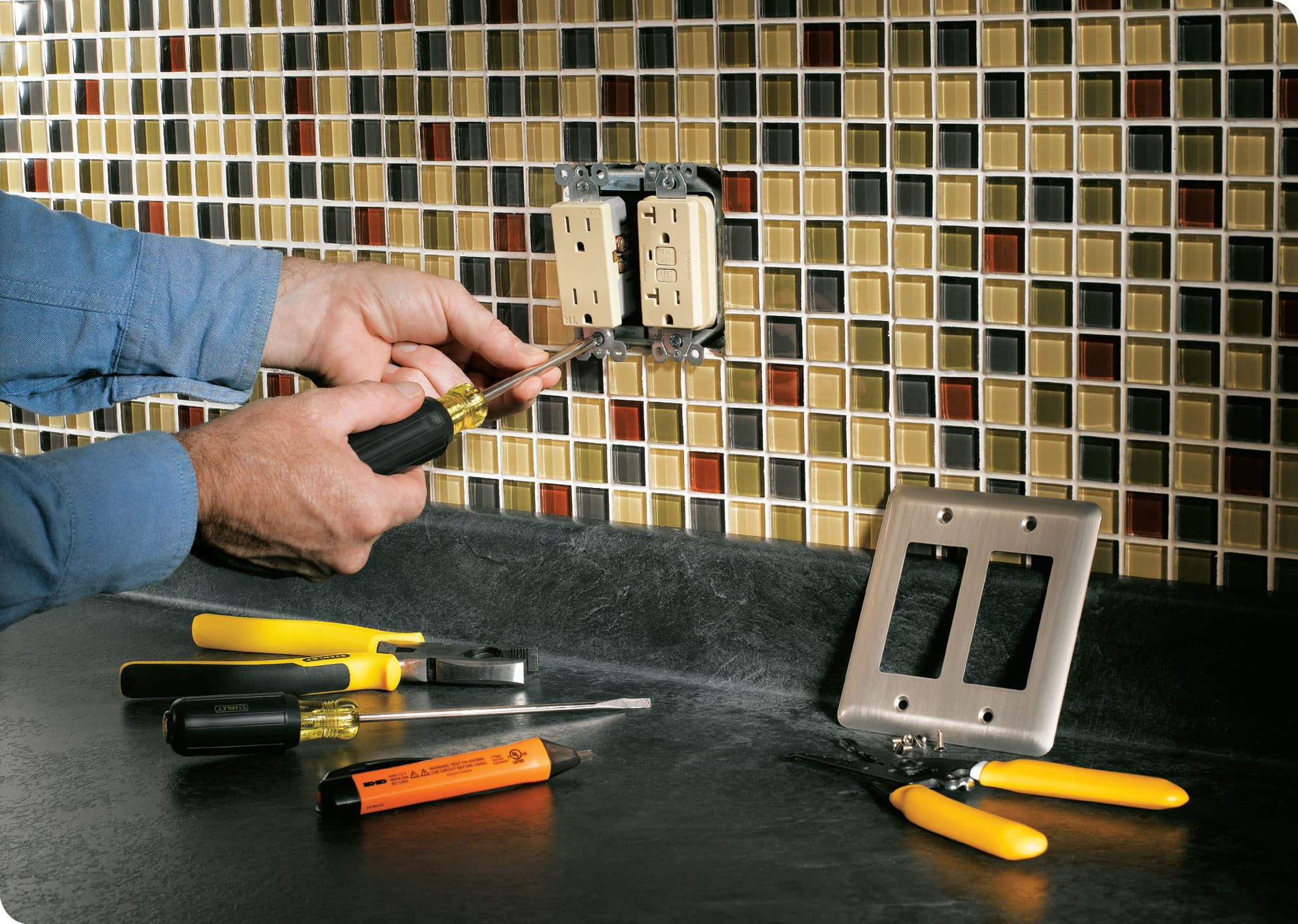
Many home wiring repair and minor improvement projects are pretty simple and only dangerous if you are not careful and don’t follow instructions and safety precautions. Some, such as replacing ordinary duplex receptacles with GFCI-protected devices will greatly improve the safety of your home.
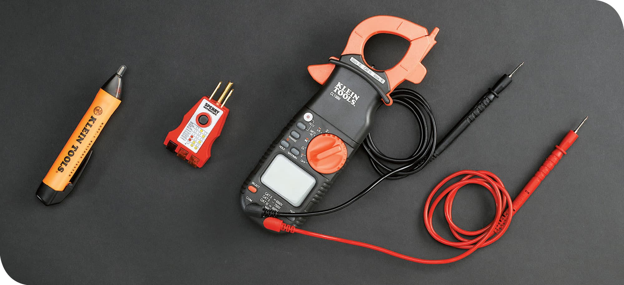
Most basic home wiring repairs can be accomplished with relatively simple hand tools, such as screwdrivers, a utility knife, and pliers. As you take on more complex projects, you’ll want to invest in some simple hand tools that are specific to home wiring. But in either case you will need some diagnostic tools to work safely, even on the simplest projects. The diagnostic tools above include, from left to right, a touchless circuit tester that lets you check for voltage without actually touching live wires or screw terminals; a plug-in tester for checking the polarity and grounding of a receptacle; and a multimeter, which is a crucial device for more complicated work but may not be needed for some of the more basic projects.

A cable ripper has one job only: to split the sheathing on wire cable (called NM cable) and expose the insulated wires inside without damaging them.

A wire stripper has graduated holes, like an old-style pencil sharpener, so you can select the opening that matches the gauge of the wire you are working with and use the tool to safely strip off the insulation without damaging the copper wire inside. You cannot make electrical connections with unstripped wire.
WIRING SAFETY
Safety should be the primary concern when working with anything having to do with electricity. Although most household electrical repairs and straightforward, always use caution and good judgment when working with electrical wiring or devices. Common sense and attentiveness prevent accidents.
The most basic rule when working with electricity is to always shut off the power to the area or device you are working on. This does not simply mean turn the switch controlling a device to “OFF.” Switches can be defective and, depending on how that particular circuit is wired, there may be live current in the wires even if the device appears to be off. Someone also could inadvertently flip the switch on. Turn off power at the main circuit panel by shutting off circuit breakers or removing fuses. If you are working in an isolated area and know which circuit you may be coming in contact with, shutting off the breaker in only that circuit should be sufficient and allows you to retain power service elsewhere in the house. But always test the wiring and devices around the work area with a voltage tester or sensor to confirm that no power is present. And test thoroughly—it is always a possibility that power from multiple circuits is entering any electrical box. The absolute safest way to ensure you will not come in contact with electrical voltage is to shut off the main breakers in your panel, which cuts off all electrical service to the house. Even then, however, test for voltage.
OTHER IMPORTANT SAFETY CONSIDERATIONS WHEN WORKING WITH ELECTRICITY:
• Do not attempt any job unless you are certain how to do it and comfortable with the work. Never guess.
• Wear rubber-sole shoes when working with wiring—they are poor conductors of electricity in the event you get a shock.
• If you need to work on a ladder, use only wood or fiberglass ones—never metal.
• If you need to replace a circuit breaker or fuse, make certain that you buy one made by the same manufacturer as the electrical panel (they are not interchangeable) and that the new device is rated for the same amperage as the one you are replacing.
• Do not drill or saw into or otherwise penetrate any wall without either shutting off all power to the house first or testing with a voltage finder—this is a different tool than the voltage tester or sensor shown here and more closely resembles an electronic stud finder (some of which also have voltage finder capability).
• Never splice wires together unless the connection is made inside a certified junction box.
• Always use a wire connector of the correct size when splicing wires: a connector that is too big or too small can allow wires to fall out. Never make a splice using only electrical tape to bind the wires: that is not the purpose of electrical tape and is not allowed by codes.
• Do not attempt to remove cable sheathing or strip insulated conductors (wires) using a knife, scissors or any tool other than one rated for that purpose (see Cable ripper and Wire stripper, shown here).
• When attaching a wire to a screw terminal, make sure the required loop at the end of the wire is slightly larger than the diameter of the screw and orient the wire so the open end will be pressed further into a closed position when the screw is tightened in a clockwise direction.
• Test all connections by tugging lightly on them to make sure the wires are held fast and will not pull out or detach from a terminal from light pressure.
• Use the right tool for the job, and make sure the tool is clean and in good condition. In most home wiring projects, a very basic set of hand tools should include needle-nose pliers, linesman pliers (or wire cutters), phillips and slotted screwdrivers. Other tools will be required situationally.
• Never force wires or devices into a junction box. If you have the appropriate amount of cable extending into the box and do a neat job of arranging the connectors, any device you are mounting on the box should easily fit onto the box without pressure.
• Use only the regulation screws that are provided with your junction box to attach devices and faceplates to the box. A screw that it too long can extend too far into the box and contact the wires. One that is too narrow or wide or improperly threaded can slip out.
• Do not hesitate to contact a professional electrician when you encounter a situation that is outside of your knowledge and comfort level.
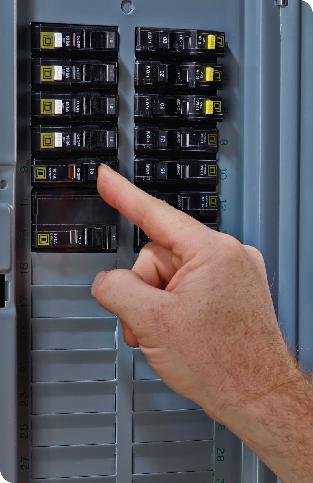
Locate and inspect your main service panel before starting any job. If your circuit map is up to date, try shutting off the power to the likely circuit you want to work on by flipping the switch on the appropriate breaker to OFF. Test the device you will be working on with a touchless circuit tester to make sure it is not receiving power. If there is any doubt in your mind, shut off the main circuit breakers at the top of the panel that provide power to all circuits.
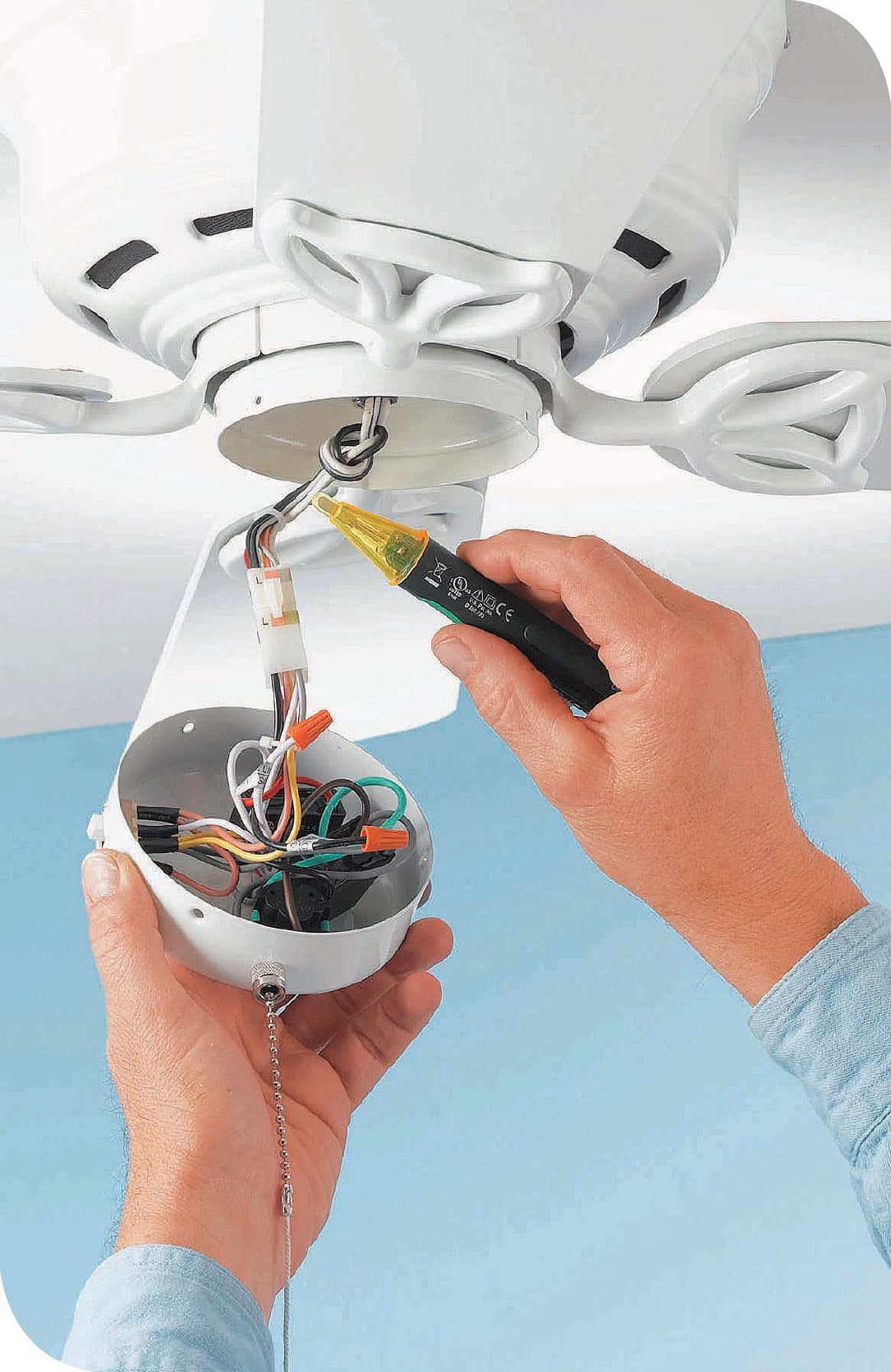
Shut off power, and test the wires by placing a touchless voltage sensor within 1/2" of the wires. If the sensor beeps or lights up, then the circuit is still live and is not safe to work on. When the sensor does not beep or light up, the circuit is dead and may be worked upon. “Touchless” testers are safer than older neon circuit testers because you do not have to contact any potentially live wires.
BASIC WIRING SKILLS
Following are a few of the most elementary skills for working with electrical systems that are you may encounter when attempting the scope of repair projects featured in this book. Several of them you will not likely need, since the projects in this book are largely one-for-one replacements of devices and electrical fixtures and, therefore, do not require you to run new wiring. But because there are possible situations where you would need to work with new wires or cables (usually NM cable—which stands for nonmetallic), we are including some basic handling skills here. More complex projects will, of course, require more advanced skills that you will need to learn before attempting them.
How to Reset a Circuit Breaker

Open the door of the main service panel and locate the tripped breaker. It should be the only one flipped to an OFF position, and there is usually a red tab exposed.
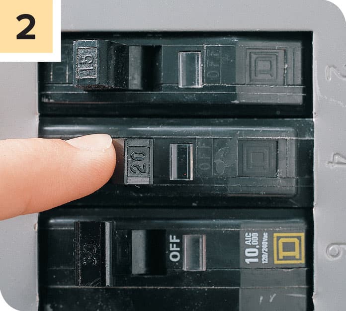
To reset the breaker, first press the lever all the way to the OFF position, and then back to the ON position. If you were successful you should hear a clicking sound.
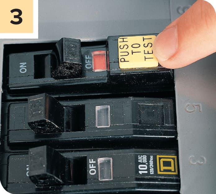
If an AFCI and GFCI breaker trips, press the “Push” button after you reset the breaker. If the breaker is functioning properly, it will trip to the OFF position. If it does not, the breaker likely is faulty and needs replacement.
How to Remove NM Cable Sheathing
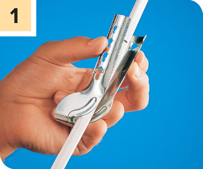
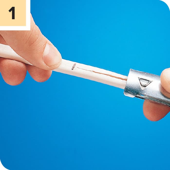
Feed the end of the cable into a cable ripper so the cutting point is 8" to 10" from the end and precisely centered side to side. Squeeze the tool to pierce the cable sheathing. Do not loosen your grip.

Holding the cable tightly, pull back on the cable ripper tool to create a longitudinal slice through the sheathing and insulating paper, all the way to the end.

Pull down the sheathing and paper all the way to the initial point of the cut. Trim off the excess with scissors or the cutting jaws of a linesman pliers or a combination wire-stripper tool.
How to Strip Wire Insulation
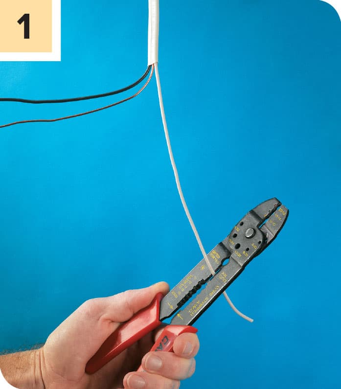
Cut the insulated conductors from your stripped cable (see previous page) so the wires extend 3" past the point where the sheathing resumes. You can use wire cutters or the cutting jaws on a combination wiring tool.
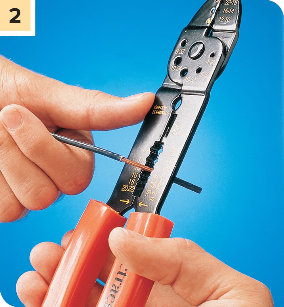
Insert each insulated conductor into the appropriately sized opening on your wire stripper or combination tool (in most homes this will be either 12 or 14-gauge). Clamp the jaws of the tool onto the insulation 3/4" from the end. Rotate the tool back and forth slightly to pierce the sheathing all the way around, and then press the tool toward the end of the wire. The insulation should slide along the wire and drop off when you reach the end.
How to Connect Wires to Screw Terminals
Strip 3/4" of insulation from the wires in your cable (see previous page). With needle-nose pliers, bend a “C” shaped loop into the end of each wire. Avoid scratching the wire. The diameter of the C should be roughly 1/4".

Unscrew the screw terminal on the device you are connecting to just enough to create clearance for the wire loops. Hook each wire loop over onto the shaft the correct screw terminal so the open end of the C is on the clockwise-turning side of the screw. Note that some devices have a slot in the casing next to the terminal for the wire to rest in. Make sure the feed side of the wire is in this slot to get the sturdiest connection. Use some tension to keep the loop in place as you tighten the screw so the screw head does not dislodge the loop. Tug lightly on the feed wire after you are done to make sure the connection is secure.
How to Join Wires with a Wire Connector
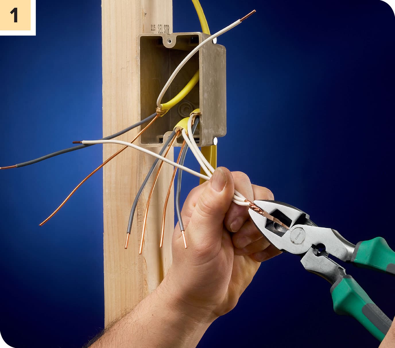
Ensure power is off and test for power. Grasp the wires to be joined in the jaws of a pair of linesman pliers. The ends of the wires should be flush and they should be parallel and touching. Rotate the pliers clockwise two or three turns to twist the wire ends together.

Twist a wire connector over the ends of the wires. Make sure the connector is the right size. Hand-twist the connector as far onto the wires as you can. There should be no bare wire exposed beneath the collar of the connector.
How to Pigtail Wires

NOTE: Pigtailing is done mainly to avoid connecting multiple wires to one terminal, which is a code violation.
Cut a 6" length from a piece of insulated wire the same gauge and color as the wires it will be joining. Strip 3/4" of insulation from each end of the insulated wire.
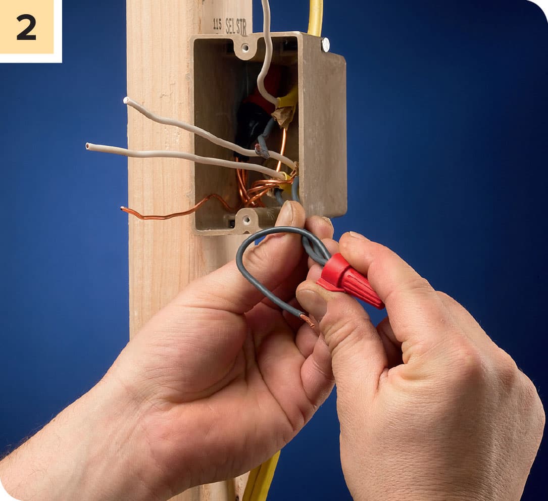
Join one end of the pigtail to the wires that will share the connection using a wire nut.
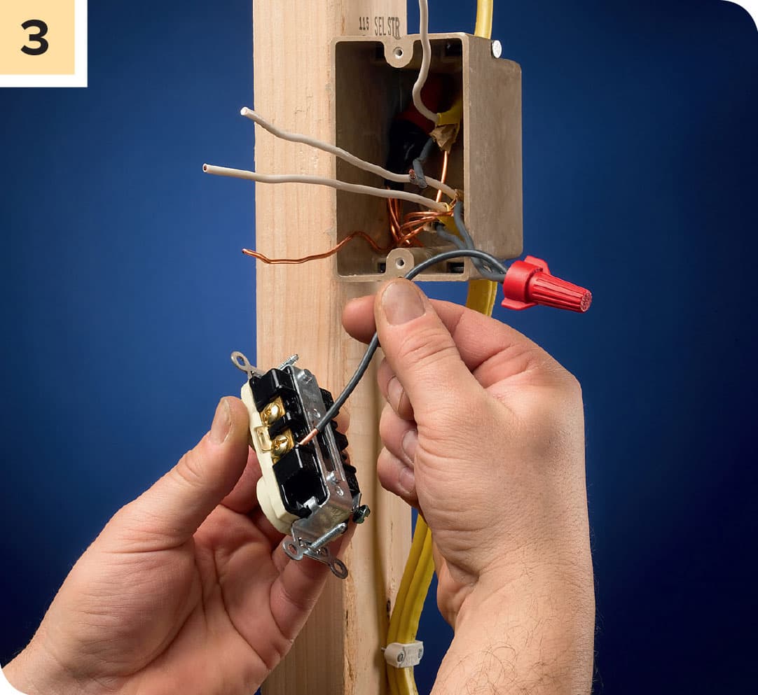
Connect the pigtail to the appropriate terminal on the receptacle or switch. Fold the wires neatly and press the fitting into the box.
REPLACING SWITCHES
Switches need replacement more than other electrical devices for a few reasons: They have moving parts and tend to wear out; They can have a prominent impact on your home décor and are often swapped out to change color or mechanic (lever versus rocker); New technical advances such as motion-activated switches, timed switches, or dimmer switches are more available and popular with homeowners.
Standard switches often confuse homeowners because they are unique in that they only have one wire connection (excepting the ground). The white neutral actually bypasses the switch and only the black power wire runs through it. The principle is simple: the power comes in through the switch. When the switch is open, power goes into the switch, passes through it, and comes out to an outgoing wire on the other side that leads to the switched device.

How a typical single-pole wall switch is wired depends on whether it is located in the middle of a circuit or at the end. It’s a little complicated and has to do with whether or not there are multiple switches controlling a single fixture, usually a light. If the switch is in the middle, two 3-wire cables will be in the switch box: one from the power source and the other heading out to the load. If it is on the end, only one cable with three or four wires comes into the box.

If you are making a one-for-one switch replacement, it is usually safe to assume that the old switch was wired correctly, and simply get a new switch that is configured like the old one and hook it up the same way.
How to Replace a Wall Switch
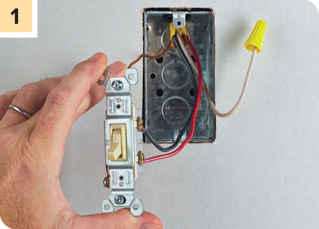
Turn off power to the switch at the main service panel. Remove the coverplate and the switch mounting screws. Withdraw the switch from the box, noting the locations of the wires and which terminals they are connected to.
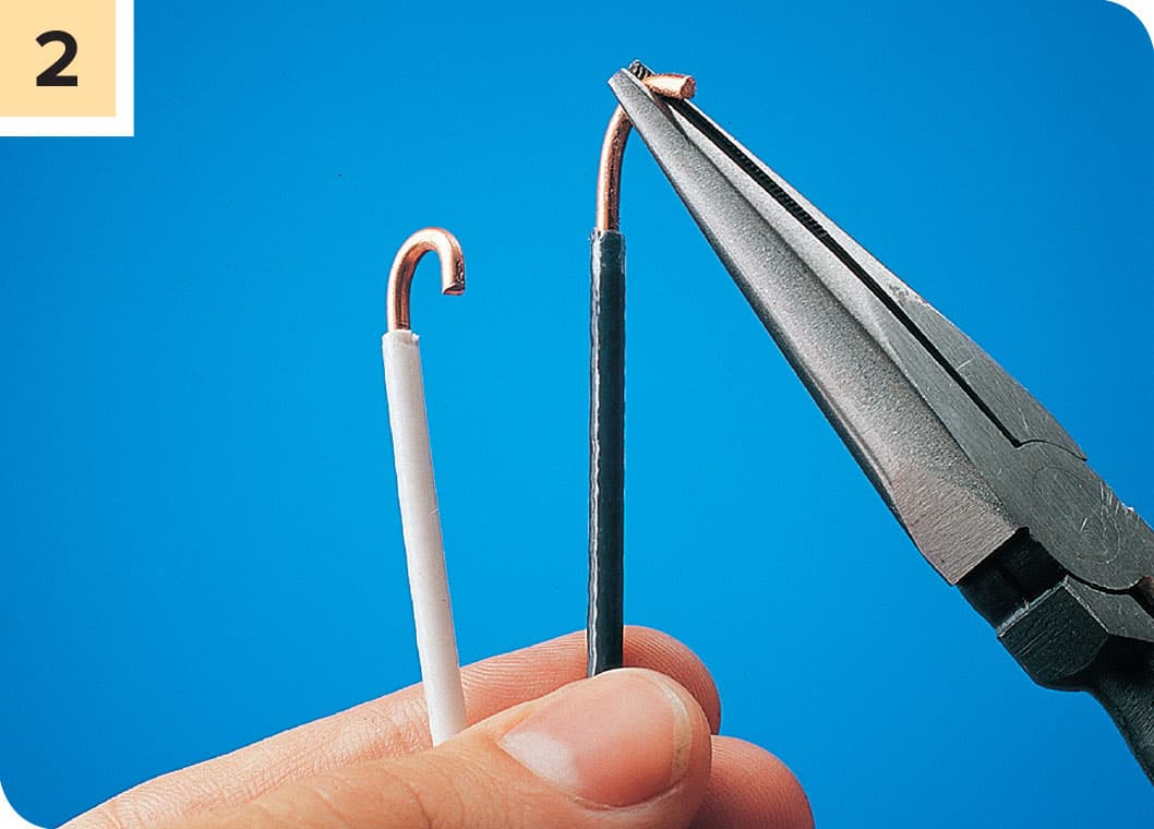
Disconnect the wires from the old switch. If the wires are not in pristine condition, strip off some insulation, cut 1/4" to 1/2" of wire to create a clean end, and then rebend the terminal connection loops on the wires (see here). If the wires coming into the box were connected directly to the switch, reconnect them to the new switch in the same configuration. If the old wires were connected to the switch with pigtails (see previous page), create new pigtail wires and connect them to the new switch and to the incoming and outgoing wires in the same manner. Connect the grounding wire (usually bare copper) to the green grounding terminal on the switch. Fold the wire neatly behind the switch and insert the device back into the switch box. Fasten it to the box with the mounting screws and test. Reattach the coverplate.
Three-way Light Switches

Three-way switches are configured to enable two different switches to control a single fixture, usually a light. They are very common at the top and bottom of stairs. They are rather complicated, but if you need to replace a switch that looks like this, with three wire terminals (not including the grounding terminal), you can simply purchase a new three-way switch and hook it up the same way. Once you have the old switch out of the switch box, it’s a good idea to tag the wire with tape the wire that is connected to the “Common” terminal on the old switch, since making sure this wire is connected to the “COM” terminal on the new one is the key to getting it right.
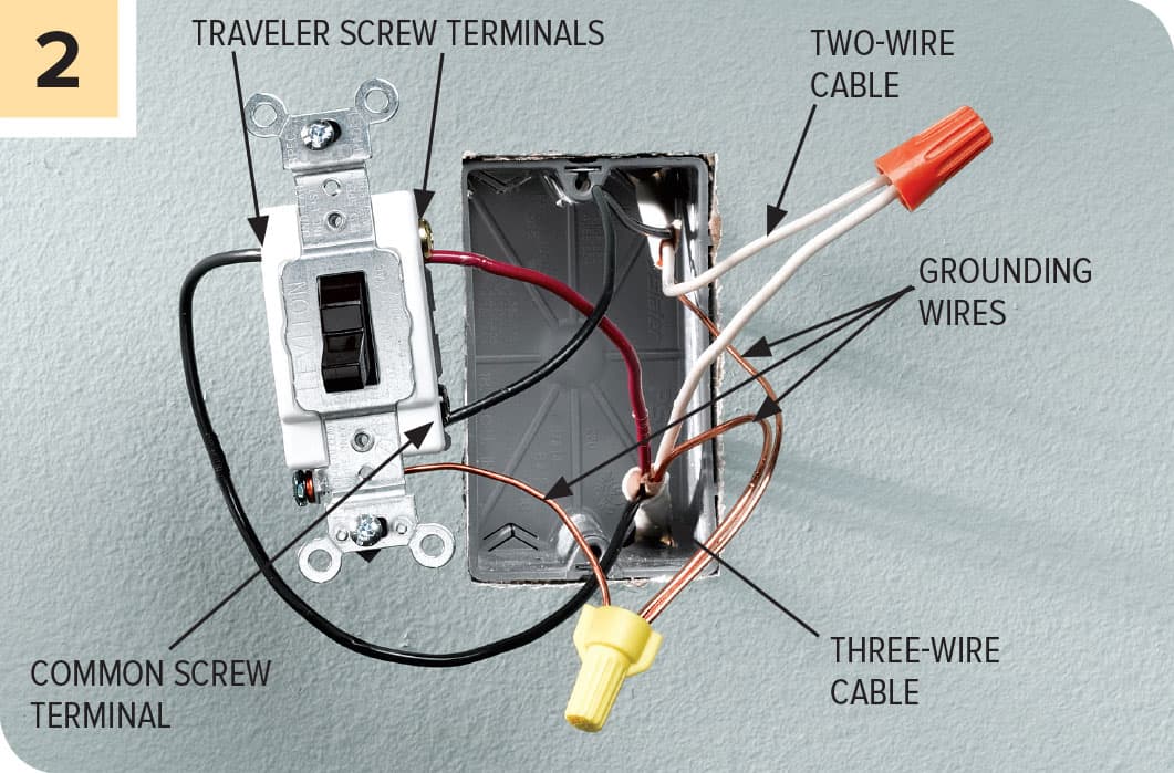
The typical wiring scheme of a three-way switch. The key to getting the replacement right is to make sure the two traveler wires are connected to the two traveler terminal on the switch, and the common wire is connected to the common terminal on the new switch. The white neutrals should be connected with a wire connector but not attached to the switch. The ground wires should be pigtailed from the incoming cable and to the switch grounding terminal and then connected to the grounding screw on the switch box.
REPLACING RECEPTACLES
Receptacles (many call them plug-ins) are pretty reliable, but occasionally one will short-circuit or the electrical contacts will separate, causing failure. Your home may have old two-slot receptacles that you’d like to upgrade to three-prong types with a ground to accept a three-prong plug (not as simple as swapping out with a new device). You may wish to bring your kitchen or bathroom up to code by replacing a standard receptacle with one that has built-in Ground-fault Current Interrupter protection (this is a simple one-for-one replacement). You may even want to replace your plug-in simply to update the look of your walls, although you will not find as wide a selection of designer receptacles, like you will for switches.
The main considerations when replacing a receptacle are:
• SAFETY Be sure the circuit power is shut off and test thoroughly with a touchless voltage sensor (see here).
• Make sure the replacement device has the same amperage rating (usually 15 or 20 amps) as the one you are replacing
• Make sure the wires that are attached to the new receptacle are in solid condition and the wire connections (be they screw terminals or push-in) are very secure.
• The new receptacle should be securely mounted to the box with the correct mounting screws.
• The coverplate should fully conceal the wall opening containing the receptacle box, with no gaps anywhere.
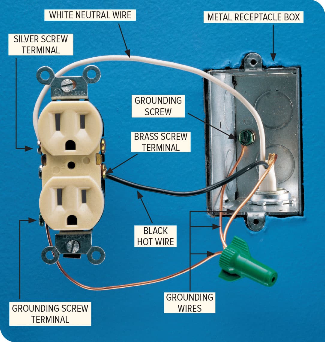
Typical duplex receptacles are wired, like switches, differently according to whether they are located in the middle or end of a circuit. Also like switches, it is good to understand the difference if you are replacing a receptacle, but in most cases simply hooking up the new device in the same manner will give you good results. But always check your installation with a plug-in tester (see here) to make sure it is functioning properly. The photo above represents an end-of-run installation where no additional receptacles or devices follow the receptacle in the circuit. In this case, only one cable enters the box and two of the screw terminals are unused. In the following photo, both an incoming cable and an outgoing cable are present, and all four terminal are connected.

Types of Receptacles
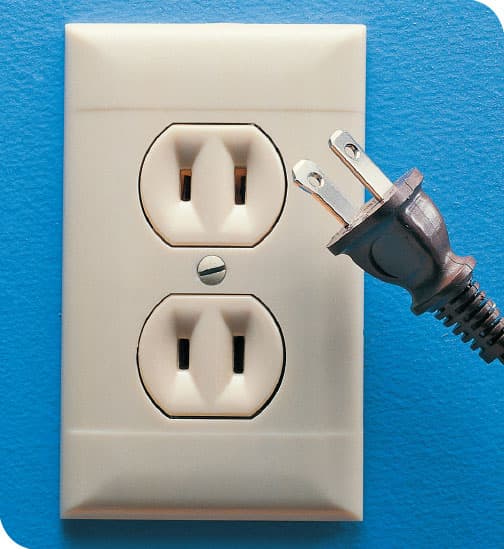
15-amp, 120-volt two-slot receptacles have not been installed with any frequency for over 50 years. The later ones have one tall slot and one short slot to accommodate polarized plugs. If you have these in your house, you probably have a drawer full of three-prong plug-in adapters as well. For ease of use, these may be replaced with three-slot receptacles, but test the new receptacle with a plug-in tester to see if it is grounded. If not, the receptacle box or the house wiring are not properly grounded, in which case you should consult an electrician.

15-amp, 120-volt three-slot receptacles are standard in 15-amp home circuits. See “Up or Down” below. The device shown here is also tamper-resistant in that the slots are protected so children can’t poke small items into them. Tamper-resistant receptacles are required in new construction.
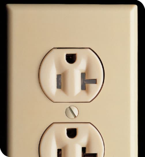
20-amp, 120-volt receptacles are designed for 20-amp circuits, required in kitchens, among other places. The T-shaped slot identifies them as 20-amp and accommodates the plugs on some appliances and tools that draw high amperage and, therefore, have a corresponding T-shaped plug.
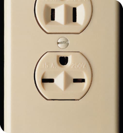
15-amp, 240-volt receptacles have two horizontal slots and are installed on a 240-volt circuit. They are used most often for window air conditioners. Other 240-volt receptacles, installed mostly on dedicated clothes dryer or electric water heater or oven circuits, carry higher amperage (30 or 50 amps on most cases) also have unique slot configurations. Because of their high amperage, it is best to have them serviced by a professional electrician if they develop issues.
Tips for Working with Receptacles

A plug-in tester is a very important and very easy-to-use wiring diagnostic tool. The tool contains three lights and if the receptacle is improperly connected it will display various illumination patterns most have an on-board key. They will identify if the receptacle is not properly grounded or if a continuity problem exists, but there are other possible miswiring issues it cannot detect that can be diagnosed only with a multimeter.
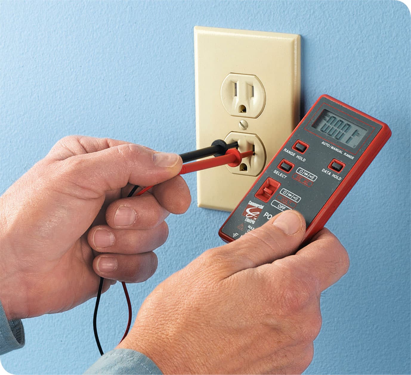
A multimeter (also called an ammeter) is a more advanced wiring-diagnostic tool that can perform multiple diagnostic functions depending on the settings. They are very useful tools to have if you wish to advance your home wiring skills. Using one correctly takes some studying, so read the manual carefully if you buy one.
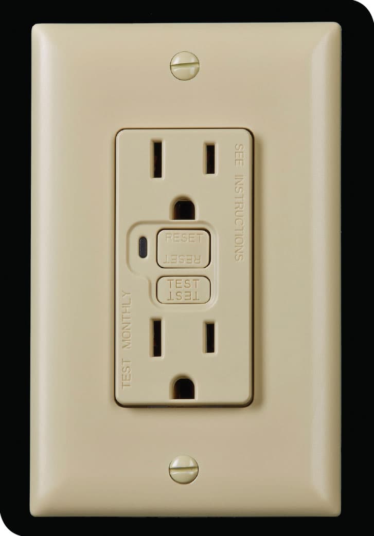
GFCI receptacles provide point-of-service ground fault protection and are required in any area of the home where moisture is present, including kitchens, bathrooms, basement, and garages. They are rated for either 15- or 20-amp circuits, so make sure the one you buy matches the amperage of the circuit it is being installed in (see previous page). You can also provide ground fault protection to an entire circuit by installing a GFCI circuit breaker in your main panel. See here.
Common Mistakes Made Wiring Receptacles
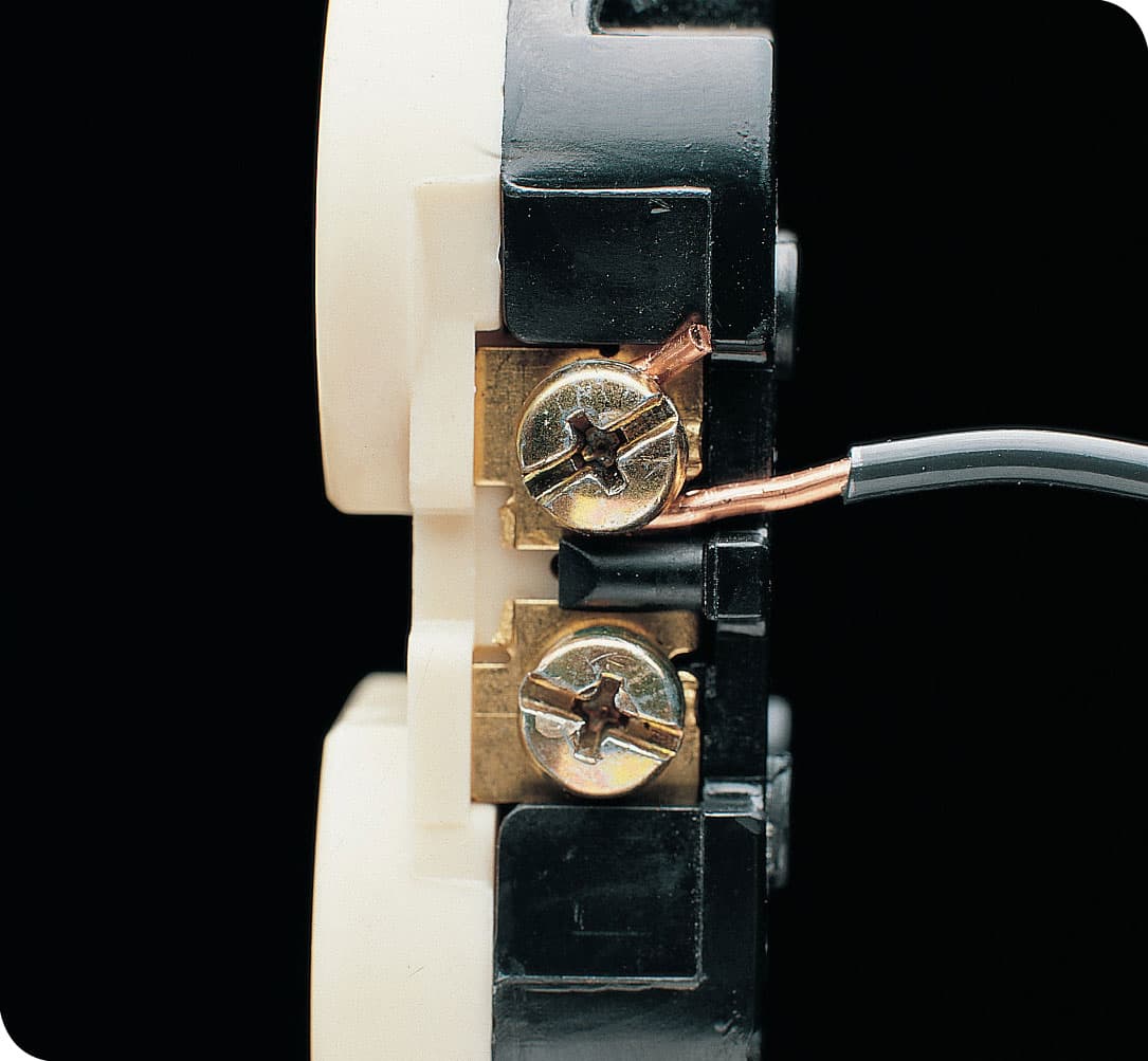
Mistake: Bare wires extend past a screw terminal. Exposed wires can cause a short circuit if they come in contact with a metal receptacle box or other wires inside the box. Here, there is too much exposed wire on both the infeed and outfeed side of the terminal.
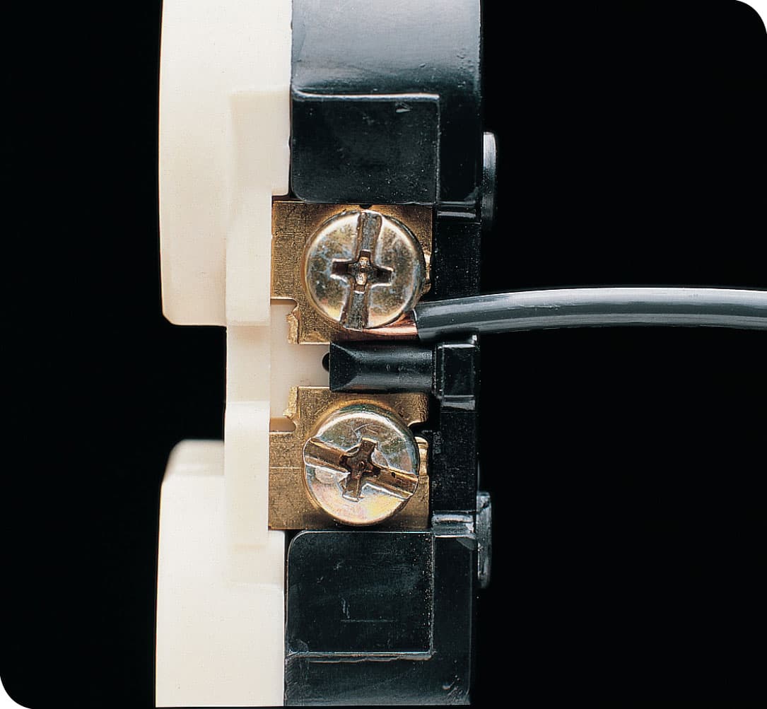
Correct: Wire insulation touches the screw terminal and the loose end of the wire is tucked neatly underneath the terminal screwhead.
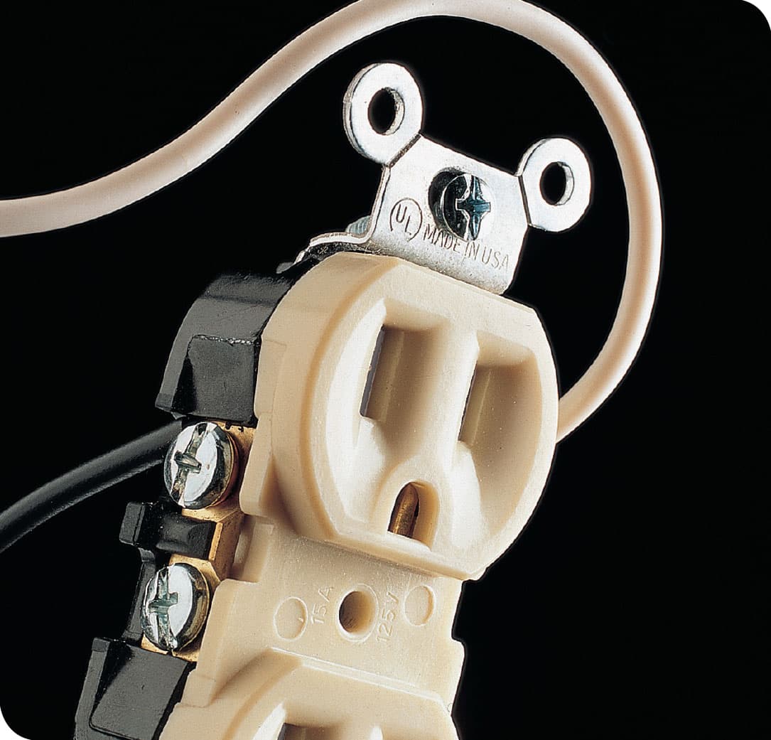
Mistake: Wires are connected to the wrong terminals. Receptacles have brass and silver terminals: brass is for the live wires (usually black) and silver is for the white neutral wires. Although a receptacle wired in this manner may appear to function normally, in fact it will deliver power to the long neutral slot of the receptacle, so power will be traveling to the load through the neutral path.
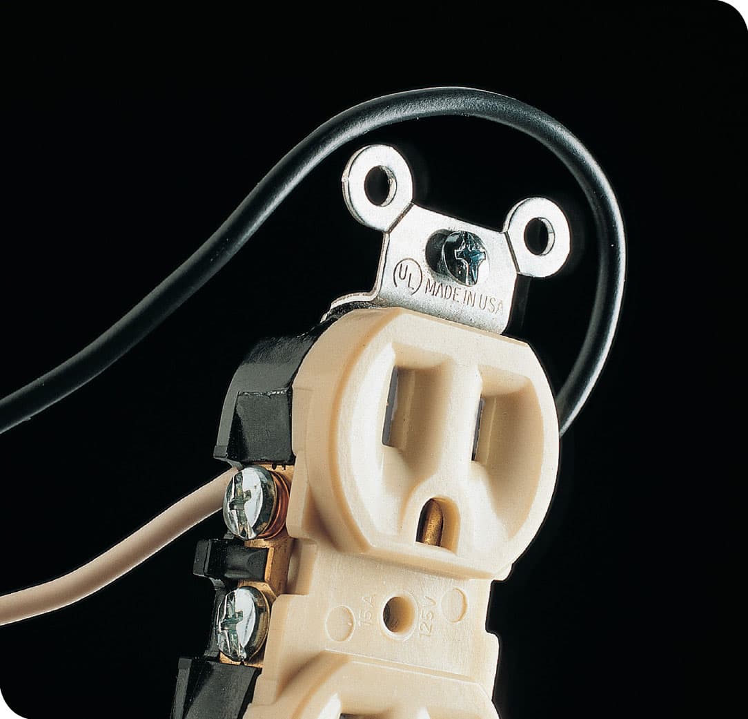
Correct: In a correct installation, all live power-carrying wires are connected to brass terminals on the receptacle, and all white neutral wire are connected to silver terminals.
NOTE: One of the limitations of plug-in testers (previous page) is that most will not detect if current is flowing to the neutral slot. You’ll need to either test with a multimeter or make a visual inspection of the terminal connections.
GFCI RECEPTACLES
If you are building a new house or doing a major remodeling project, it is required that all circuits in potentially wet areas have ground fault interruption protection. But even if your home is not undergoing remodeling, replacing standard receptacles with GFCI receptacles is a very prudent idea because it means you will have a safer home.
GFCI receptacles are basically sensors that detect changes in current flow and instantly shut off power to any device on the protected circuit. This is important because the current usually are caused by faults in the appliances that are plugged into the circuit. Faults can be caused by an electrical malfunction or short circuit in the appliance (possibly caused by exposure to moisture), which can easily lead to a fire.
If you replace an ordinary receptacle with a GFCI receptacle, everything you plug into that outlet will be protected, but the entire circuit will not be. You can solve this by replacing all of the receptacles on the circuit with a GFCI receptacle. You can also wire one GFCI in a series fashion so it protects all outlets down-line from it. This is efficient, and also a relatively tricky wiring job unless you have a lot of wiring experience. It also increasing the likelihood of nuisance tripping of the one GFCI, which can happen when you get an occasional (and not dangerous) small drop in current flow. The best protection is to replace the breaker for that circuit in your main service panel with a GFCI breaker. This, too, is not a job for a begging home electrician.
NOTE: The sequence on the next page shows how to replace a standard receptacle with a GFCI. If you are simply making a one-for-one replacement of a standard receptacle, the steps are the same.

GFCI receptacles have two buttons: TEST and RESET. To ensure that they are functioning, press the TEST button manufacturers suggest you test at least once a year. This should cause the outlet to lose power immediately. Then push the RESET button to restore power. If the GFCI trips from an occasional nuisance change in current level, hit the RESET button. If the GFCI trips again, it likely means that one of the appliances plugged into that outlet has a fault.
How to Install a GFCI for Single-Location Protection
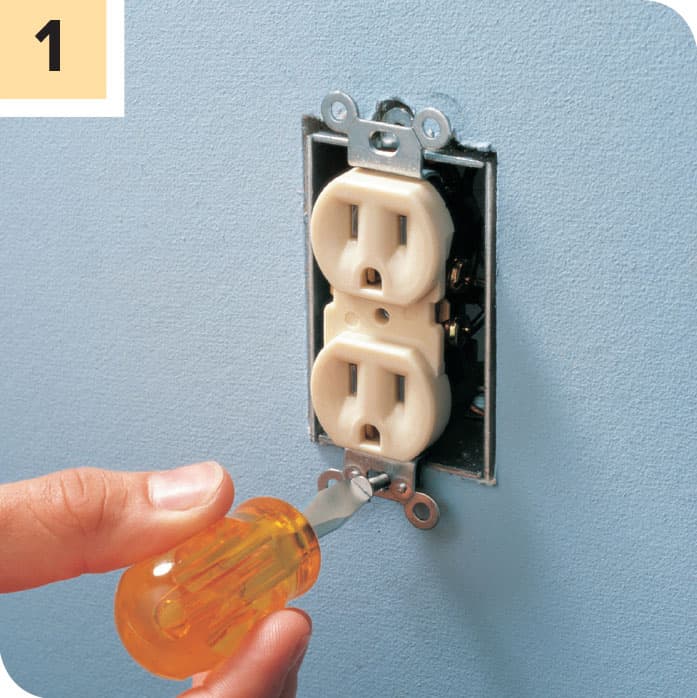
Shut off power to the circuit at the main circuit breaker and test with a voltage sensor. Remove the coverplate and the mounting screws holding the receptacle to the box. Without touching the screw terminals or wires, withdraw the receptacle from the box. Test again to confirm it is not getting power.

Disconnect the white neutral wires from the old receptacle first. Create a white wire pigtail if none is present in the box (see here). Join all white wires in the box, plus the pigtail, with an appropriate wire connector (see here).
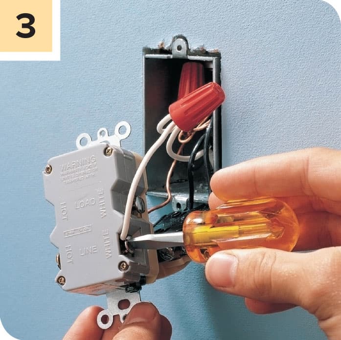
Connect the free end of the white pigtail wire to the silver terminal marked LINE on the GFCI receptacle.
NOTE: The installation shown here is for single-location protection. Your GFCI receptacle will have a second set of brass and silver terminals marked “LOAD.” These are for use if you are wiring the device to feed additional circuits downstream. For the project shown here do not attach any wires to the LINE terminals.
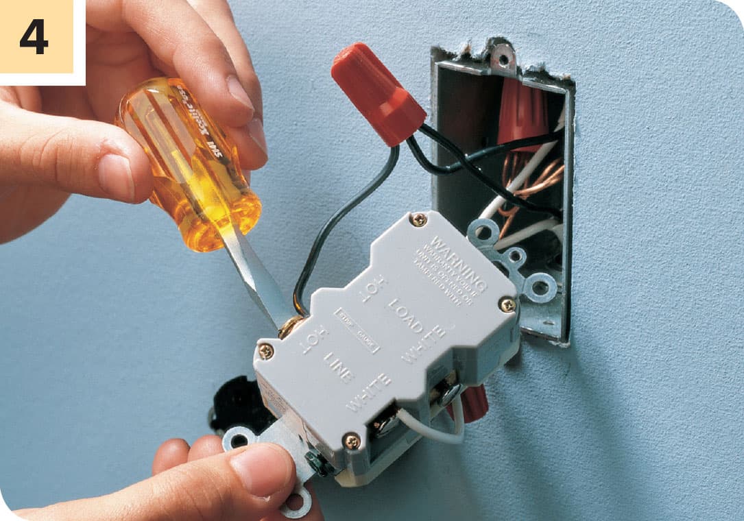
Disconnect all black wires from the old receptacle. Create a black pigtail if none is present. Connect all black wires in the box, plus the pigtail, with an appropriate wire connector. Attach the free end of the pigtail to the brass terminal marked LINE on the GFCI receptacle.
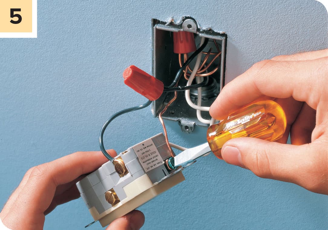
If a grounding wire is available, connect it to the green grounding screw on the GFCI. Neatly fold the wires behind the GFCI and insert it into the receptacle box. Because GFCI receptacles have slightly larger bodies than standard receptacles, the fit is likely to be more snug than it was with the old unit. Do not force the GFCI in. If the box is overcrowded, it will need to be replaced with a larger box. Mount the GFCI to box with the provided mounting screws and attach the coverplate (usually provided with the GFCI).
REPAIRING LIGHT FIXTURES
Light fixtures are attached permanently to ceilings or walls. They include wall-hung sconces, ceiling-hung globe fixtures, recessed light fixtures, and chandeliers. Most light fixtures are easy to repair using basic tools and inexpensive parts.
If a light fixture fails, always make sure the lightbulb is screwed in tightly and is not burned out. A faulty lightbulb is the most common cause of light fixture failure. If the light fixture is controlled by a wall switch, also check the switch as a possible source of problems.
Light fixtures can fail because the sockets or built-in switches wear out. Some fixtures have sockets and switches that can be removed for minor repairs. These parts are held to the base of the fixture with mounting screws or clips. Other fixtures have sockets and switches that are joined permanently to the base. If this type of fixture fails, purchase and install a new light fixture.
Damage to light fixtures can occur because homeowners install lightbulbs with wattage ratings that are too high. Prevent overheating and light fixture failures by using lightbulbs that only match the wattage ratings printed on the fixtures.
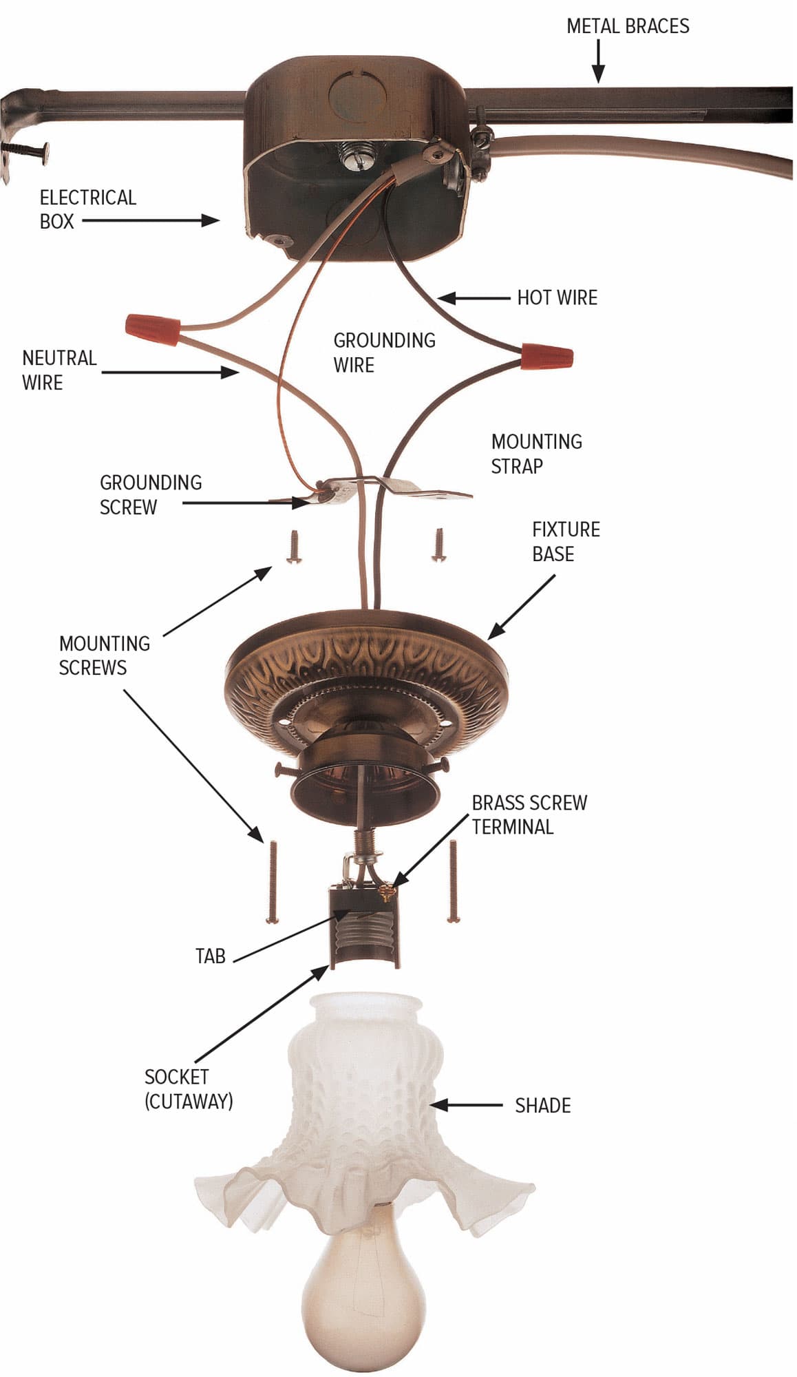
In a typical light fixture, a black hot wire is connected to a brass screw terminal on the socket. Power flows to a small tab at the bottom of the metal socket and through a metal filament inside an incandescent bulb. The power heats the filament and causes it to glow. If you are using compact fluorescent bulbs, the electricity flowing through the socket excites the gases inside the bulb causing them to give off light. In the case of LED bulbs, the power is sent to microchips that redirect it to light emitting diodes. In all cases, the current then flows back through the threaded portion of the socket and through the white neutral wire back to the main service panel.

Before 1959, light fixtures often were mounted directly to an electrical box or to plaster lath. Electrical codes now require that fixtures be attached to mounting straps that are anchored to the electrical boxes. If you have a light fixture attached to plaster lath, install an approved electrical box with a mounting strap to support the fixture.
How to Remove a Light Fixture & Test a Socket
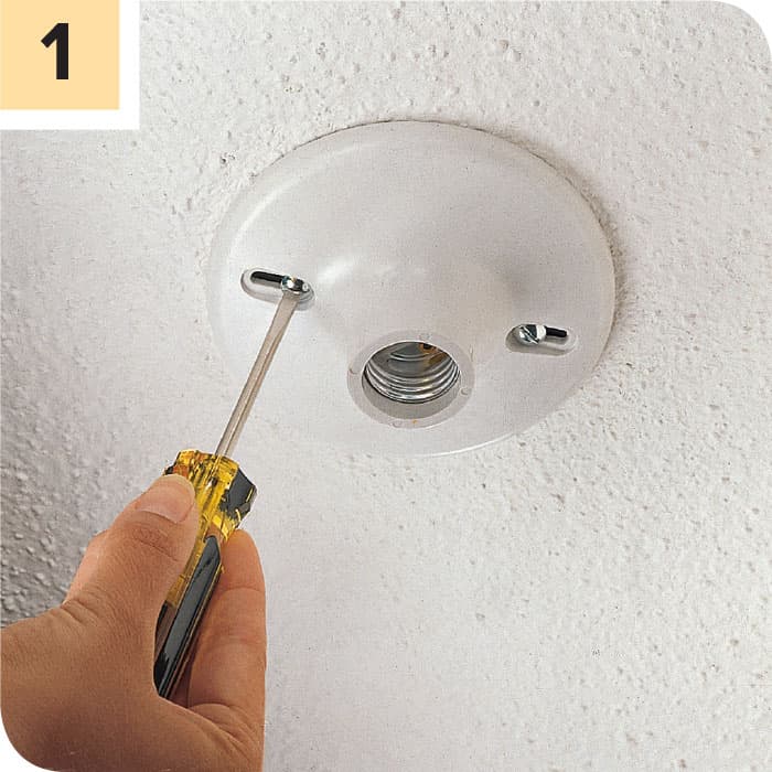
Turn off the power to the light fixture at the main panel. Remove the lightbulb and any shade or globe, then remove the mounting screws holding the fixture base and the electrical box or mounting strap. Carefully pull the fixture base away from the box. Test for power with a circuit tester.
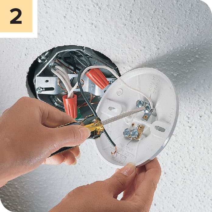
Disconnect the light fixture base by loosening the screw terminals. If the fixture has wire leads instead of screw terminals, remove the light fixture base by unscrewing the wire connectors.
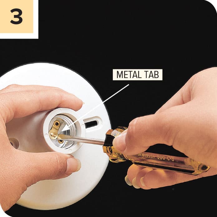
Adjust the metal tab at the bottom of the fixture socket by prying it up slightly with a small screwdriver. This adjustment will improve the contact between the socket and the lightbulb.

Test the socket (shown cutaway) by attaching the clip of a multimeter (see here) to the hot screw terminal (or black wire lead) and touching the probe of the tester to the metal tab in the bottom of the socket. The multimeter should indicate continuity. If not, the socket is faulty and must be replaced.

Attach the multimeter clip to the neutral screw terminal (or white wire lead), and touch the probe to the threaded portion of the socket. The multimeter should indicate continuity. If not, the socket is faulty and must be replaced. If the socket is permanently attached, replace the fixture.
How to Replace a Socket
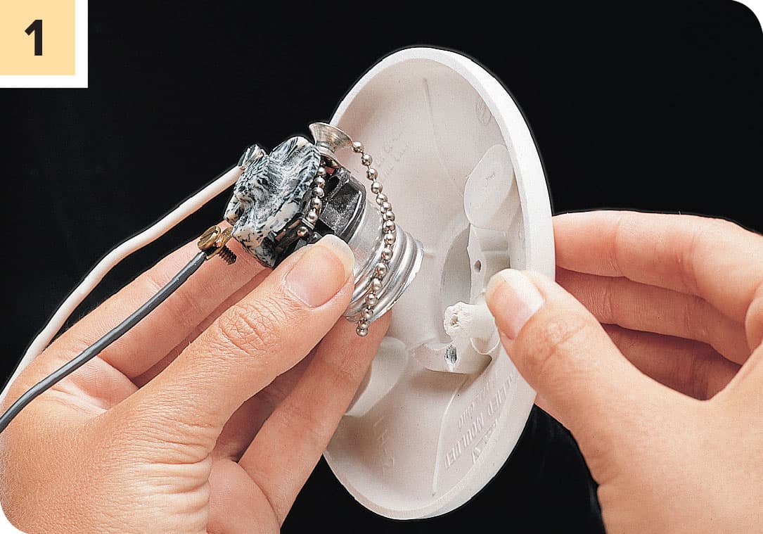
Remove the old light fixture. Remove the socket from the fixture. The socket may be held by a screw, clip, or retaining ring. Disconnect wires attached to the socket.

Purchase an identical replacement socket. Connect the white wire to the silver screw terminal on the socket, and connect the black wire to the brass screw terminal. Attach the socket to the fixture base, and reinstall the fixture.
How to Test & Replace a Built-in Light Switch
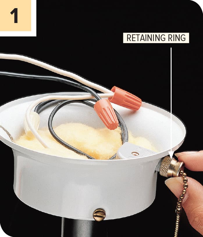
Remove the light fixture. Unscrew the retaining ring holding the switch.
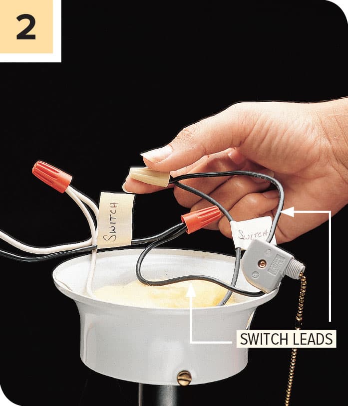
Label the wires connected to the switch leads. Disconnect the switch leads, and remove the switch.
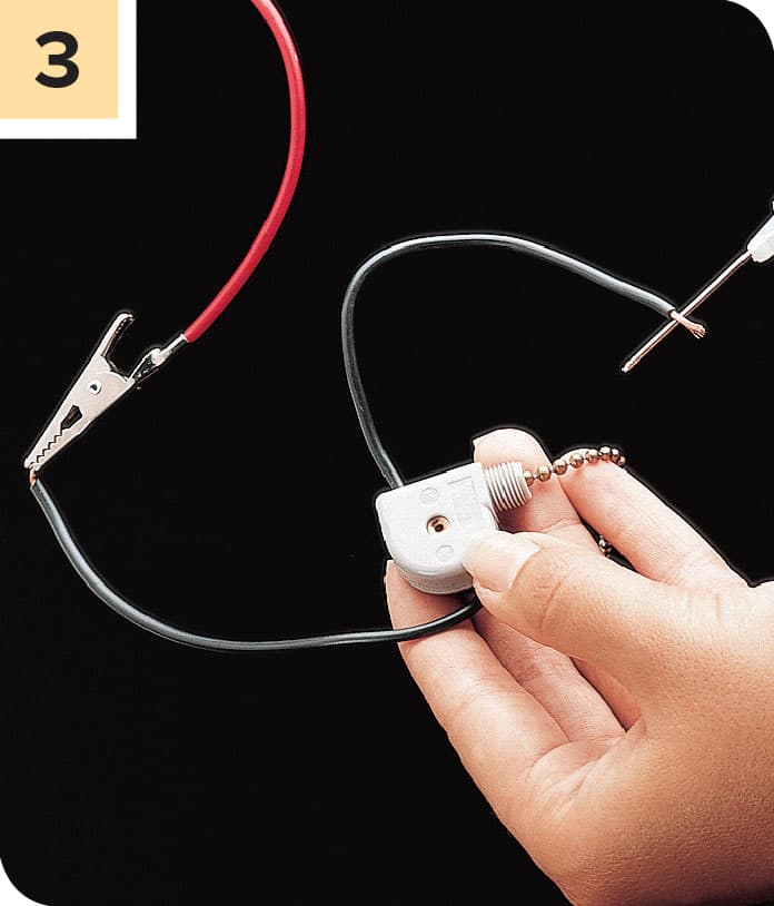
Test the switch by attaching the clip of a multimeter to one of the switch leads and holding the probe to the other lead. Operate the switch control. If the switch is good, the multimeter will indicate continuity when the switch is in one position but not both. If the switch is faulty, purchase and install a duplicate switch. Remount the light fixture, and turn on the power at the main service panel.
REPAIRING CHANDELIERS
Repairing a chandelier requires special care. Because chandeliers are heavy, it is a good idea to work with a helper when removing a chandelier. Support the fixture to prevent its weight from pulling against the wires.
Chandeliers have two fixture wires that are threaded through the support chain from the electrical box to the hollow base of the chandelier. The socket wires connect to the fixture wires inside this base.
Fixture wires are identified as hot and neutral. Look closely for a raised stripe on one of the wires. This is the neutral wire that is connected to the white circuit wire and white socket wire. The other smooth fixture wire is hot and is connected to the black wires.
If you have a newer chandelier, it may have a grounding wire that runs through the support chain to the electrical box. If this wire is present, make sure it is connected to the grounding wires in the electrical box
How to Repair a Chandelier

Label any lights that are not working using masking tape. Turn off power to the fixture at the panel. Remove lightbulbs and all shades or globes.
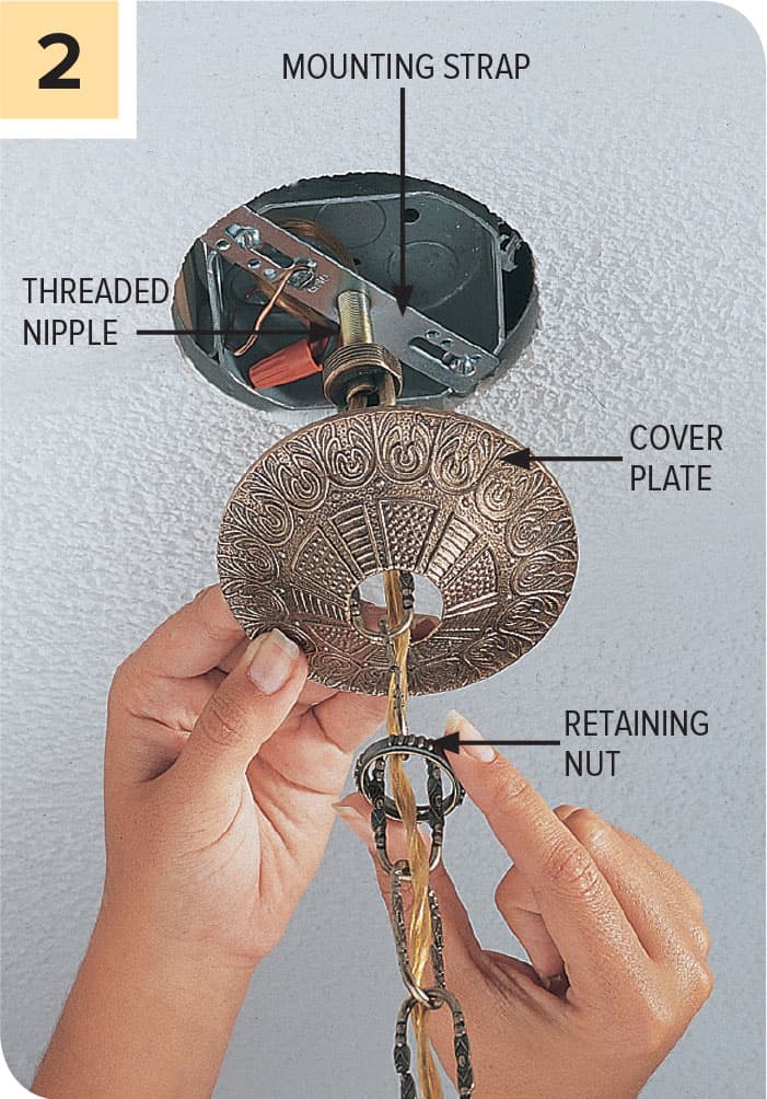
Turn off power at the main panel. Unscrew the retaining nut, and lower the decorative coverplate away from the electrical box. Most chandeliers are supported by a threaded nipple attached to a mounting strap.

MOUNTING VARIATION: Some chandeliers are supported only by the coverplate that is bolted to the electrical box mounting strap. These types do not have a threaded nipple.
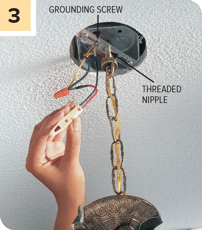
Test for power with a circuit tester. Disconnect fixture wires by removing the wire connectors. Unscrew the threaded nipple and carefully place the chandelier on a flat surface.
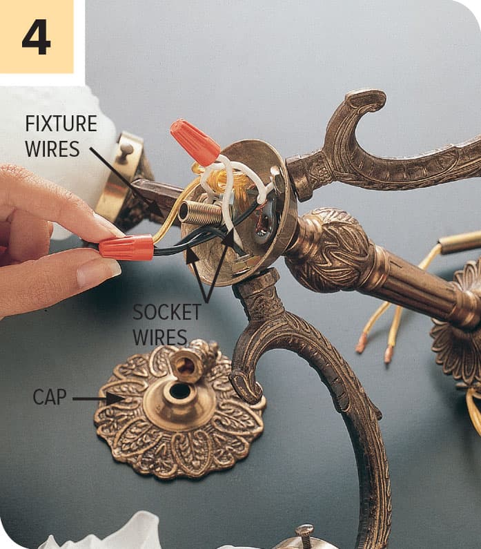
Remove the cap from the bottom of the chandelier, exposing the wire connections inside the hollow base. Disconnect the socket wires and fixture wires.

Test the socket by attaching the clip of the multimeter to the black socket wire and touching the probe to the tab in the socket. Repeat with the socket threads and the white socket wire. If the multimeter does not indicate continuity, the socket must be replaced.

Remove a faulty socket by loosening any mounting screws or clips and pulling the socket and socket wires out of the fixture arm. Purchase and install a new chandelier socket, threading the socket wires through the fixture arm.
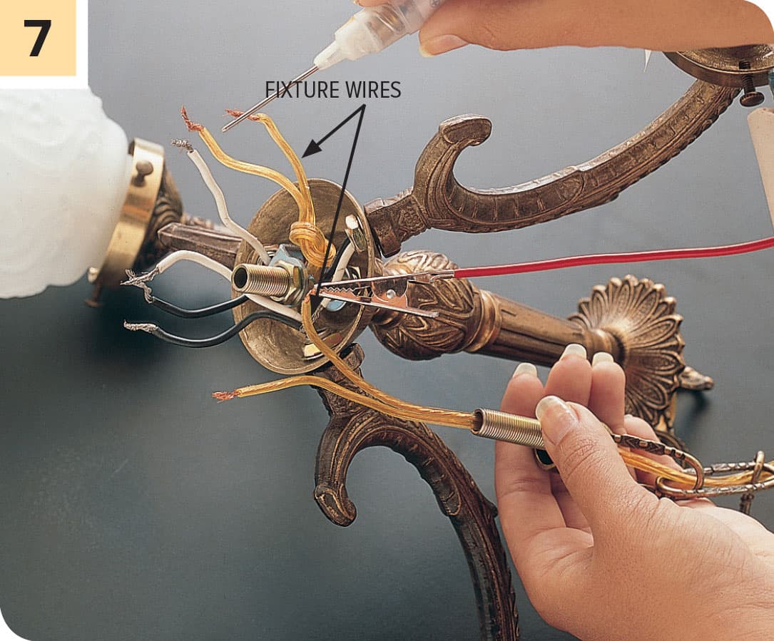
Test each fixture wire by attaching the clip of the multimeter to one end of the wire and touching the probe to other end. If there is no continuity, the wire must be replaced. Install new wires, if needed, then reassemble and rehang the chandelier.
FLUORESCENT LIGHTS
With the advent of compact fluorescents and LED options, the traditional fluorescent fixture, with its long tubular lamps and rectangular metal housing, or troffer, has been relegated mostly to garages, workshops and basements these days. Nevertheless, you can still find fluorescent fixtures in just about every home, and they do require attention from time to time.
Fluorescent lights are relatively trouble free and use less energy than incandescent lights. A typical fluorescent lamp lasts about three years and produces two to four times as much light per watt as a standard incandescent lightbulb. The most frequent problem with a fluorescent light fixture is a failed lamp (tube). If a fluorescent light fixture begins to flicker or does not light fully, remove and examine the lamp.
Fluorescent light fixtures also can malfunction if the sockets are cracked or worn. Inexpensive replacement sockets are available at any hardware store and can be installed in a few minutes. If a fixture does not work, even after the tube and sockets have been serviced, the ballast probably is defective. Faulty ballasts often give themselves away by making a humming sound.
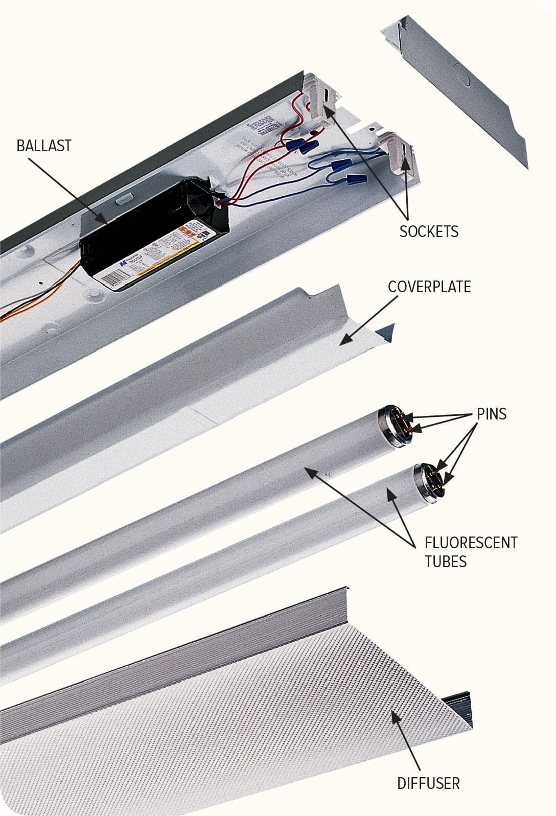
A fluorescent light works by directing electrical current through a special gas-filled tube that glows when energized. A translucent diffuser protects the fluorescent tube and softens the light. A coverplate protects a special transformer, called a ballast. The ballast regulates the flow of 120-volt household current to the sockets. The sockets transfer power to metal pins that extend into the tube.
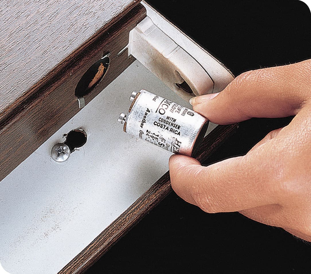
Fluorescent light fixtures usually contain a small cylindrical or button-shaped device, called a starter, located near one of the sockets. When a tube begins to flicker, replace both the tube and the starter. Turn off the power, and remove the starter by pushing it slightly and turning it counterclockwise. Install a replacement that matches the old starter.
FLOURESCENT LAMPS
The “bulb” in a fluorescent light fixture is technically called a “lamp.” Replacing a failed one is a bit trickier than screwing in a new lightbulb, and so is selecting the correct replacement lamp.
The surest way to obtain the correct fluorescent lamp is simply to bring the old lamp to the store with you and find an identical one. Most hardware stores will dispose of your old lamp for you, although some may tack on a small environmental charge for the service. Or, you can find the lamp type printed near its end. The type information starts with the letter “T,” which stands for “tube,” as in “T12.” The one-or-two-digit numeral following the T indicates the diameter in eighth-inches. So a T12 (the most common size) is 12/8" in dia., or 1 1/2". The T rating is usually preceded by an “F” and a numeral, which is the length of the lamp in inches. So a 40" lamp would be “F40.” Length measurements include the pins. If you match the F and T ratings, the lamp should fit.

If you are unsure if the lamp is burned out, make a visual inspection. The top lamp is fine and shows no blackening; the middle lamp is headed to failure and may flicker—replace it; the bottom lamp is burned out. If you have a multimeter, you can perform a continuity test on the lamp to assess its condition.
Light color
You’ll find a number of color choices, which is really a reference to the temperature of the light. In most hardware stores and building centers, you’ll see:
• “Warm” or “Warm white,” which is the closest approximation to the light temperature of an incandescent bulb.
• “Cool white” or “Bright white,” which actually has a hotter temperature than warm and is good for low-light areas like basements and garages.
• “Daylight” or “Full spectrum,” which is meant to approximate natural light and is generally easy on the eyes.
The best advice on light color is to avoid mixing them in the same room. And make sure your new lamp has the same wattage rating as the old one.
How to Remove/Replace a Fluorescent Lamp
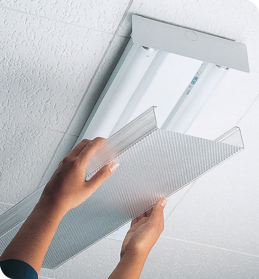
Turn off power to the light fixture at the switch. Remove the diffuser—be careful, these can be fragile. Most often you need to press inward slightly on the sides of the diffuser to release it.

Remove the fluorescent lamp by rotating it 1/4 turn in either direction and sliding the tube out of both sockets at the same time. Do not force it. To install a new lamp, align the pins on each end with the slot in each socket, insert the lamp into the sockets, and then twist it 1/4 turn in either direction until it is locked securely (inset photo). Reattach the diffuser and turn on the power at the switch.
How to Replace a Fluorescent Socket
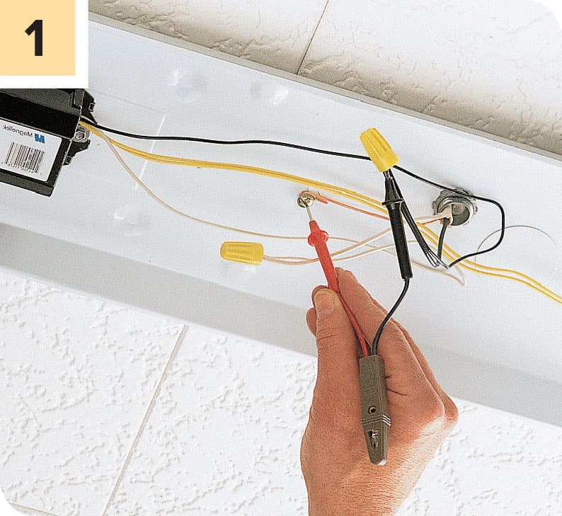
Turn off the power at the main electrical service panel, not simply at the switch. Remove the diffuser and fluorescent lamp (see previous page). Remove the coverplate protecting the ballast and fixture wiring. Test for power by touching one probe of an electrical circuit tester to the grounding screw and inserting the other probe into the hot wire connector.
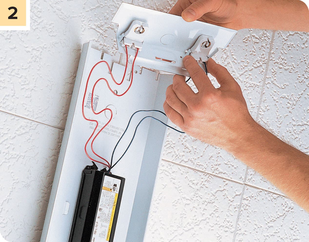
Detach the faulty socket from the fixture housing. Some sockets slide out, while others must be unscrewed.
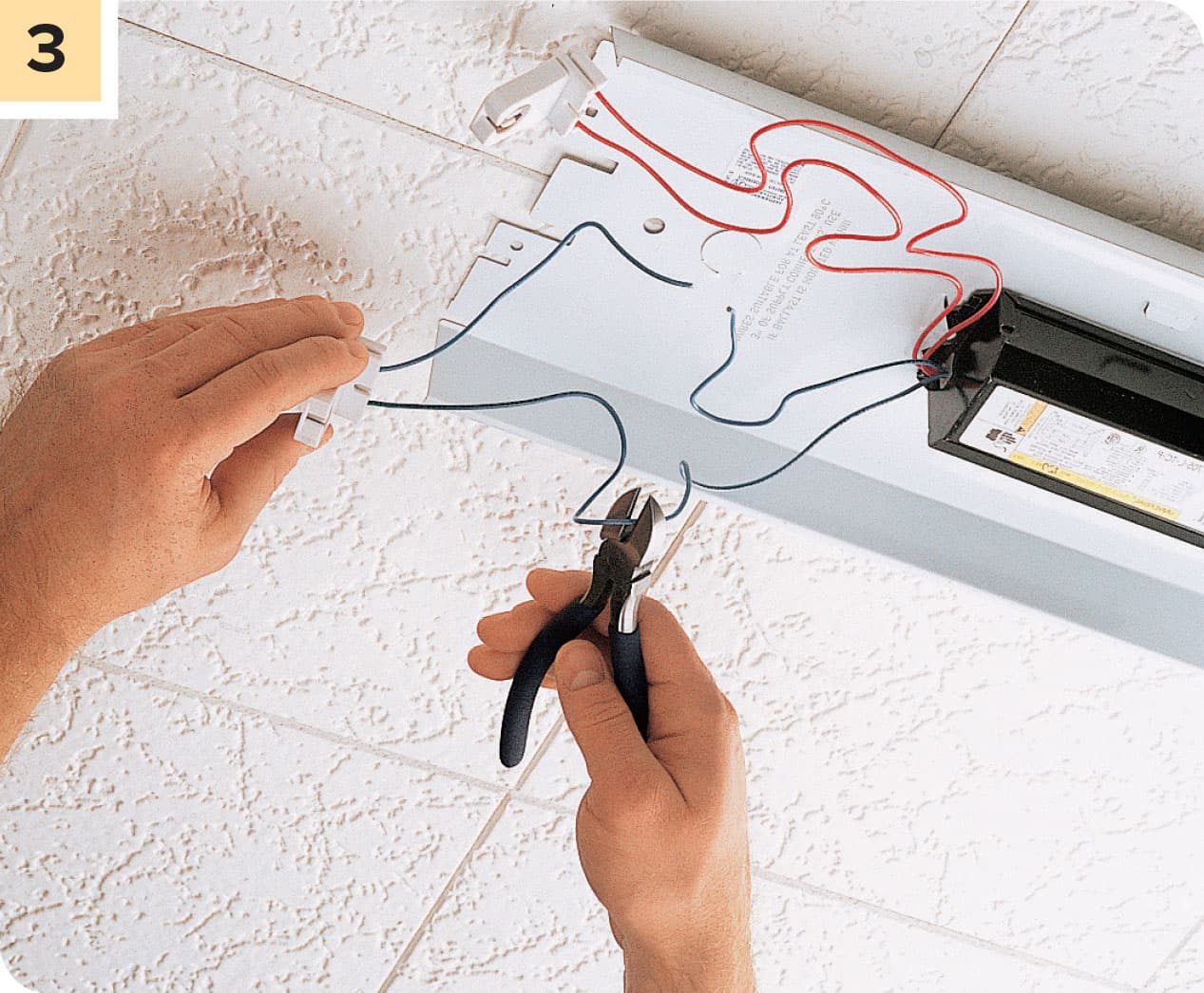
Disconnect the wires attaching the socket to the ballast. For sockets with push-in fittings, remove the wires by inserting a small screwdriver into the release openings. If your socket has screw terminal connections, loosen the screw and detach the wires. If your socket has lead wires that are fixed within the socket (as seen above), the wires must be cut.
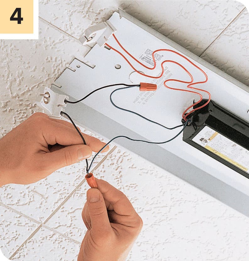
Bring the socket to the hardware store and use it as a guide to find the correct replacement. Connect the socket wires to the ballast wires by making the push-in or screw terminal connections at the socket, or by joining the ballast and socket wires with a wire connector if your socket has preattached wires (as seen above). Replace the coverplate and then the fluorescent lamp and diffuser. Restore power to the fixture at the panel and test.
How to Replace a Fluorescent Ballast
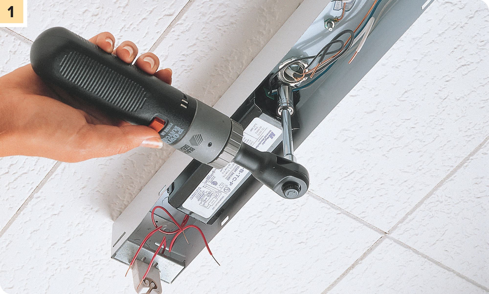
Turn off electrical power at the main service panel. Remove the diffuser, fluorescent lamp, and coverplate, and then test for power using an electrical circuit tester (see here). With the wires from the ballast disconnected, detach the ballast from the fixture housing by removing the attachment screws with a ratchet wrench or screwdriver. Support the ballast so it does not fall.
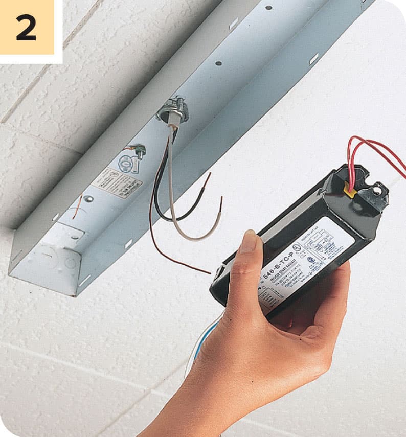
Bring the old ballast to the store and purchase a replacement ballast with the same wattage rating and physical configuration. Secure the new ballast to the fixture housing with the mounting screws.

Attach the ballast wires to the socket wires using wire connectors, screw terminal connections, or push-in fittings (see previous page). Reinstall the coverplate, and fluorescent lamp. Turn on power to the light fixture at the panel and test. Reattach the diffuser.
REPAIRING & ADJUSTING CEILING FANS
Ceiling fans contain rapidly moving parts, making them more susceptible to trouble than many other electrical fixtures. Installation is a relatively simple matter, but repairing a ceiling fan can be very frustrating. The most common problems you’ll encounter are balance and noise issues and switch failure, usually precipitated by the pull chain breaking. In most cases, both problems can be corrected without removing the fan from the ceiling. But if you have difficulty on ladders or simply don’t care to work overhead, consider removing the fan when replacing the switch.
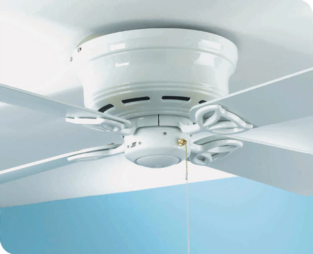
Ceiling fans are subject to a great deal of vibration and stress, so it’s not uncommon for switches and motors to fail. Minimize wear and tear by making sure blades are in balance so the fan doesn’t wobble.
How to Troubleshoot Blade Wobble

Start by checking and tightening all hardware used to attach the blades to the mounting arms and the mounting arms to the motor. Hardware tends to loosen over time, and this is frequently the cause of wobble.
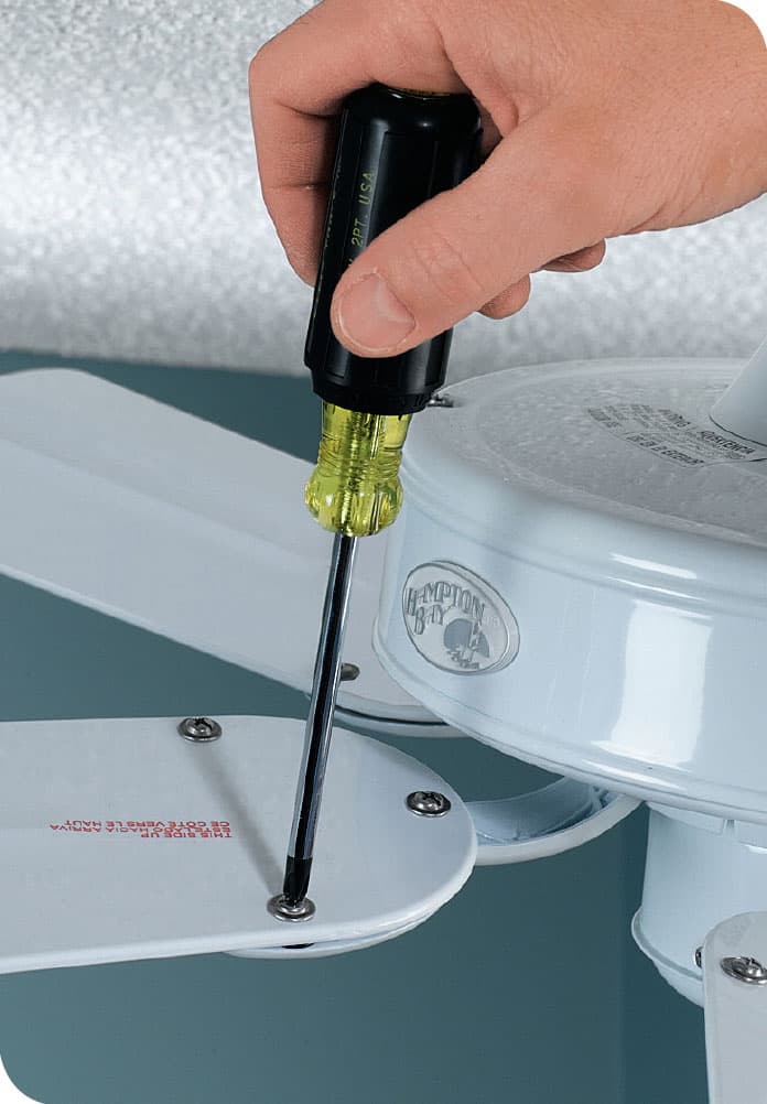
If wobble persists, try switching around two of the blades. Often this is all it takes to get the fan back into balance. If a blade is damaged or warped, replace it.

OPTION: Fan blade wobble also may be corrected using small weights that are affixed to the tops of the blades. For an easy DIY fix, you can use electrical tape and washer and some trial and error. You can also purchase fan blade weight kits for a couple of dollars. These kits include clips for marking the position of the weights as you relocate them as well as self-adhesive weights that can be stuck to the blade once you have found the sweet spot.
How to Fix a Loose Wire Connection

A leading cause of fan failure is loose wire connections. To inspect these connections, first shut off the power to the fan. Remove the fan blades to gain access, and then remove the canopy that covers the ceiling box and fan mounting bracket. Most canopies are secured with screws on the outside shell. Have a helper hold the fan body while you remove the screws so it won’t fall.
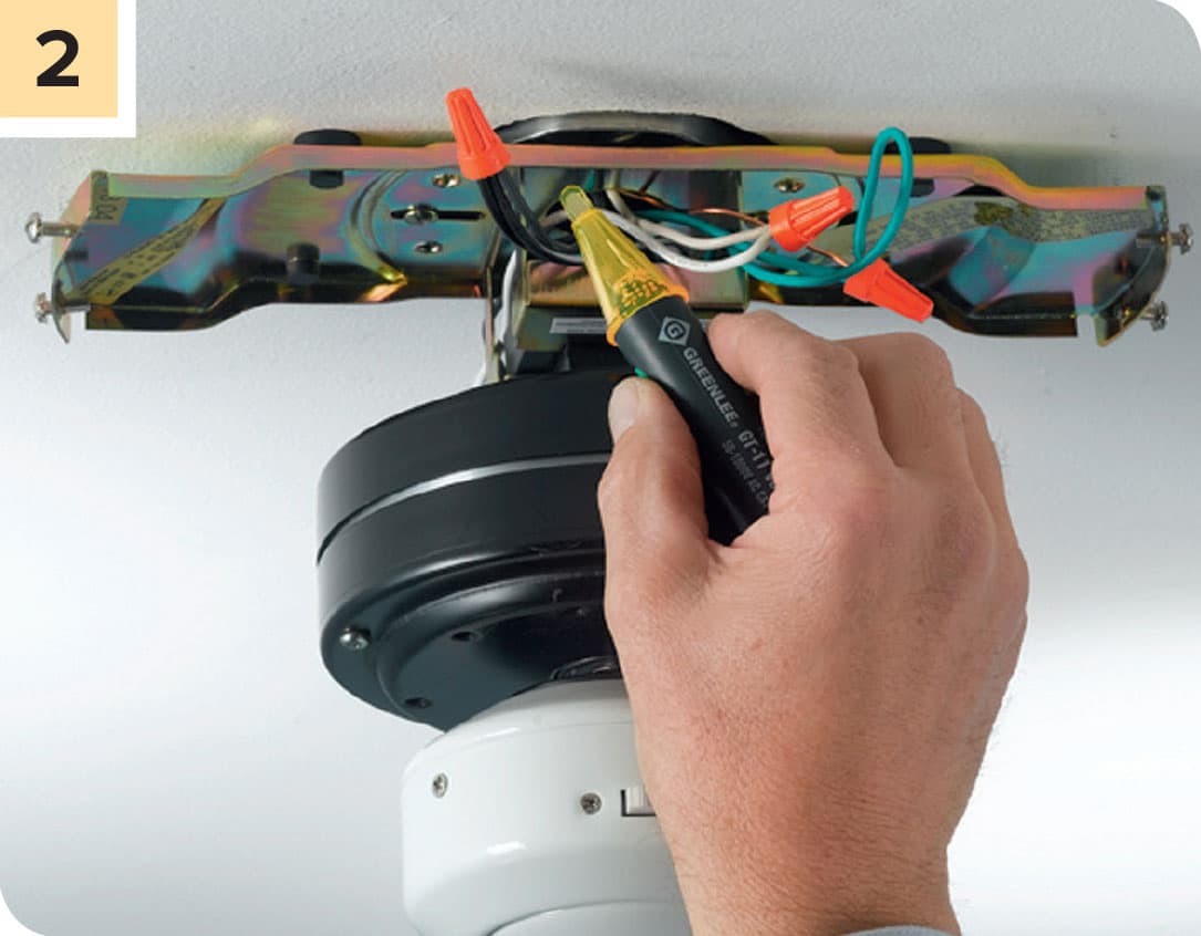
Once the canopy is removed, you’ll see black, white, green, copper, and possibly blue wires. Hold a voltage sensor within 1/2" of these wires with the wall switch that controls the fan in the ON position. The black and blue wires should cause the sensor to beep if power is present.

Shut off power and test the wires by placing a voltage sensor within 1/2" of the wires. If the sensor beeps or lights up, then the circuit is still live and is not safe to work on. When the sensor does not beep or light up, the circuit is dead and may be worked upon.

When you have confirmed that there is no power, check all the wire connections to make certain each is tight and making good contact. You may be able to see that a connection has come apart and needs to be remade. But even if you see one bad connection, check them all by gently tugging on the wire connectors. If the wires pull out of the wire connector or the connection feels loose, unscrew the wire connector from the wires. Turn the power back on and see if the problem has been solved.
How to Replace a Ceiling Fan Pull-Chain Switch

Turn off the power at the panel. Use a screwdriver to remove the three to four screws that secure the bottom cap on the fan switch housing. Lower the cap to expose the wires that supply power to the pull-chain switch.

Test the wires by placing a voltage sensor within 1/2" of the wires. If the sensor beeps or lights up, then the circuit is still live and is not safe to work on. When the sensor does not beep or light up, the circuit is dead and may be worked upon.
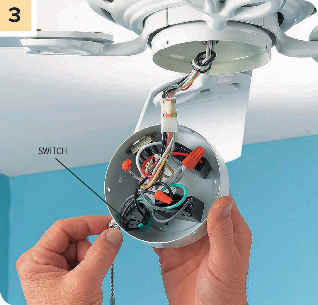
Locate the switch unit (the part that the pull chain used to be attached to if it broke off); it’s probably made of plastic. You’ll need to replace the whole switch. Fan switches are connected with three to eight wires, depending on the number of speed settings.
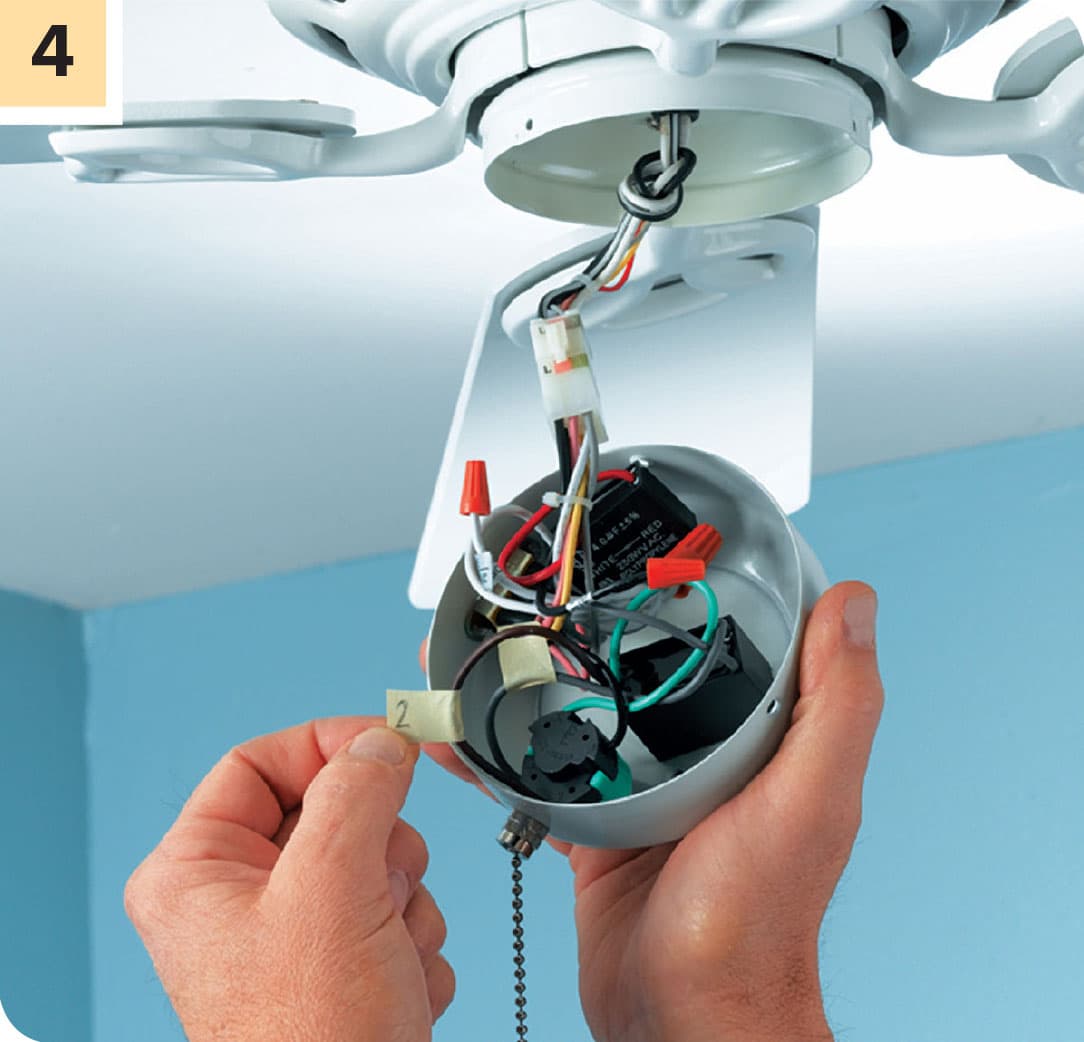
Attach a small piece of tape to each wire that enters the switch and write an identifying number on the tape. Start at one side of the switch and label the wires in the order they’re attached.
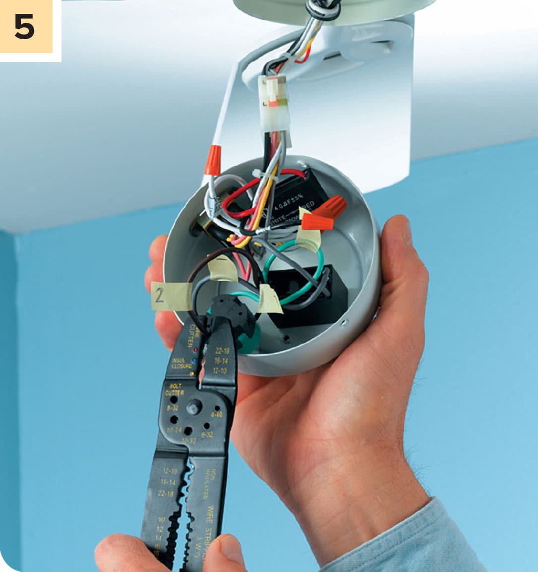
Disconnect the old switch wires, in most cases by cutting the wires off as close to the old switch as possible.
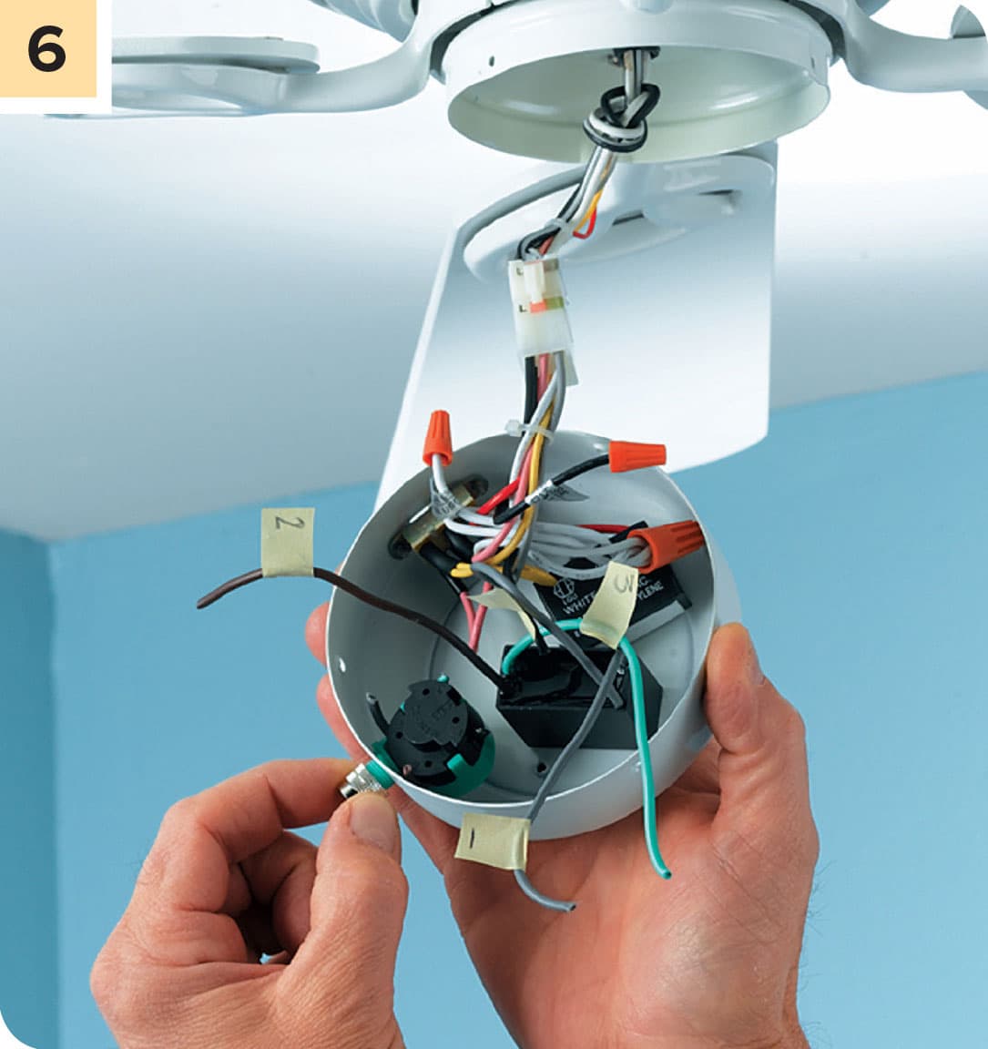
Remove the switch. Unscrew the retaining nut that secures the switch to the switch housing. There may be one or two screws that hold it in place or it may be secured to the outside of the fan with a small knurled nut, which you can loosen with needle-nose pliers. Purchase an identical new switch.

Connect the new switch using the same wiring configuration as on the old model. To make connections, first use a wire stripper to strip 3/4" of insulation from the ends of each of the wires coming from the fan motor (the ones you cut in step 5). Attach the wires to the new switch in the same order and configuration as they were attached to the old switch. Secure the new switch in the housing, and make sure all wires are tucked neatly inside. Reattach the bottom cap. Restore power to the fan. Test all the fan’s speeds to make sure all the connections are good.
REPLACING PLUGS & CORDS
Replace an electrical plug whenever you notice bent or loose prongs, a cracked or damaged casing, or a missing insulating faceplate. A damaged plug poses a shock and fire hazard. Replacement plugs are available in different styles to match common appliance cords. Always choose a replacement that is similar to the original plug. Flat-cord and quick-connect plugs are used with light-duty appliances, such as lamps and radios. Round-cord plugs are used with larger appliances, including those that have three-prong grounding plugs.
Some tools and appliances use polarized plugs. A polarized plug has one wide prong and one narrow prong, corresponding to the neutral and hot slots found in a standard receptacle.
If there is room in the plug body, tie the individual wires in an underwriter’s knot to secure the plug to the cord (see photo, opposite page, top).

Common replaceable plug types
How to Install a Quick-Connect Plug
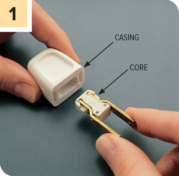
Squeeze the prongs of the new quick-connect plug together slightly and pull the plug core from the casing. Cut the old plug from the flat-cord wire with a combination tool, leaving a clean-cut end.

Feed unstripped wire through the rear of the plug casing. Spread the prongs, and then insert the wire into the opening in the rear of the core. Squeeze the prongs together; spikes inside the core penetrate the cord. Slide the casing over the core until it snaps into place.

When replacing a polarized plug, make sure that the ridged half of the cord lines up with the wider (neutral) prong of the plug.
How to Replace a Round-Cord Plug

Cut off the round cord near the old plug using a combination tool. Remove the insulating faceplate on the new plug and feed the cord through the rear of the plug. Strip about 3" of outer insulation from the round cord. Strip 3/4" insulation from the individual wires.

Tie an underwriter’s knot with the black and the white wires. Make sure the knot is located close to the edge of the stripped outer insulation. Pull the cord so that the knot slides into the plug body.
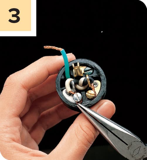
Hook the end of the black wire clockwise around the brass screw and the white wire around the silver screw. On a three-prong plug, attach the third wire to the grounding screw. If necessary, excess grounding wire can be cut away.

Tighten the screws securely, making sure the copper wires do not touch each other. Replace the insulating faceplate.
How to Replace a Flat-Cord Plug
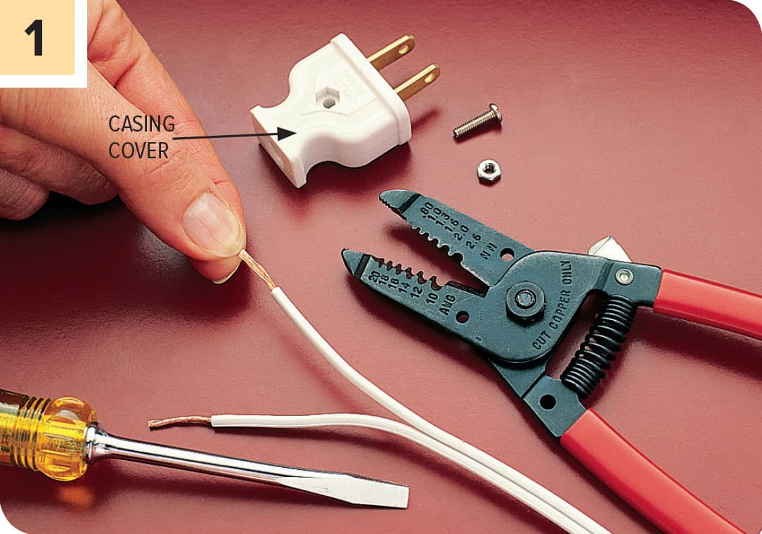
Cut the old plug from cord using a combination tool. Pull apart the two halves of the flat cord so that about 2" of wire are separated. Strip 3/4" insulation from each half. Remove the casing cover on the new plug.

Hook the ends of the wires clockwise around the screw terminals and tighten the screw terminals securely. Reassemble the plug casing. Some plugs may have an insulating faceplate that must be installed.
How to Replace a Lamp Cord
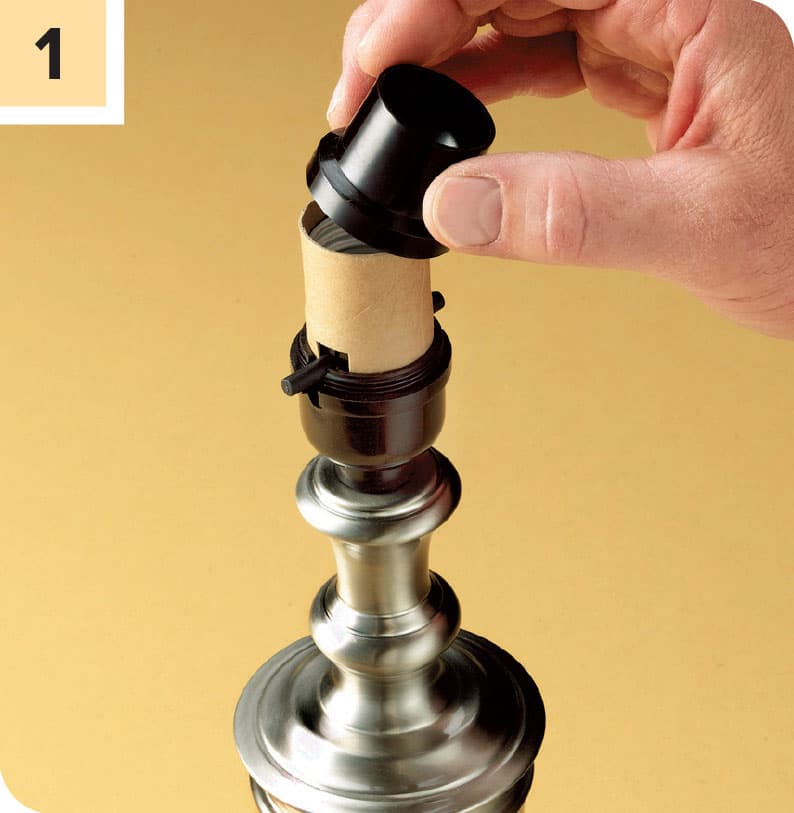
With the lamp unplugged, the shade off, and the bulb out, you can remove the socket. Squeeze the outer shell of the socket just above the base and pull the shell out of the base. The shell is often marked “Press” at some point around its perimeter. Press there and then pull.
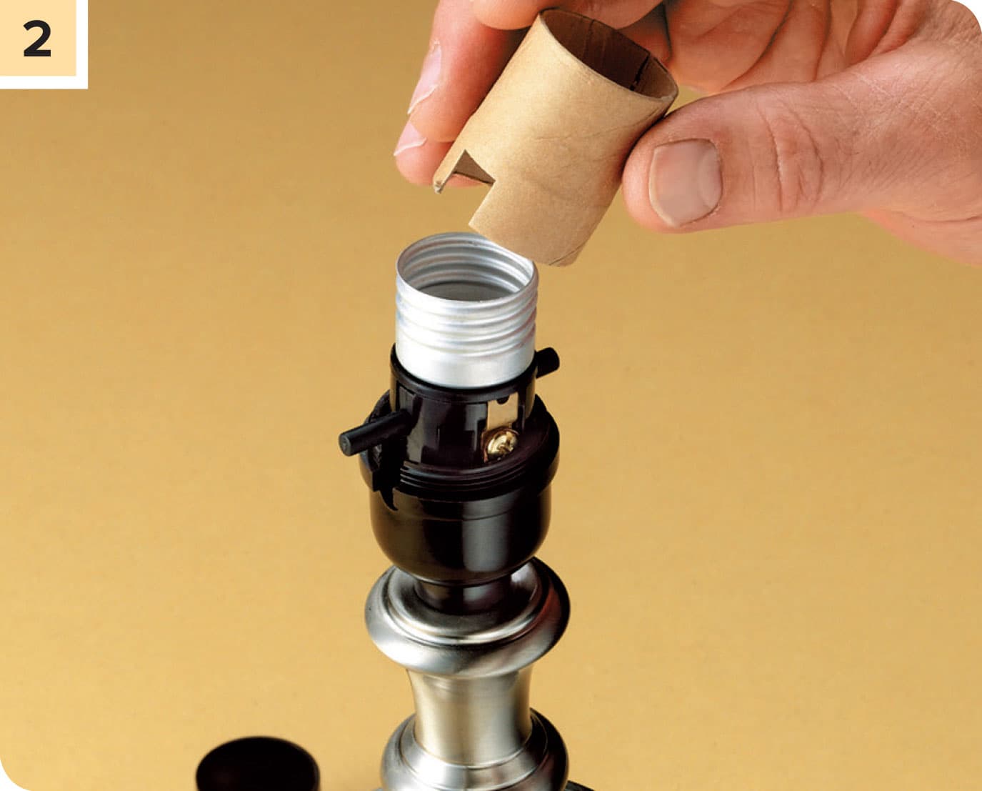
Under the outer shell, there is a cardboard insulating sleeve. Pull this off and you’ll reveal the socket attached to the end of the cord.
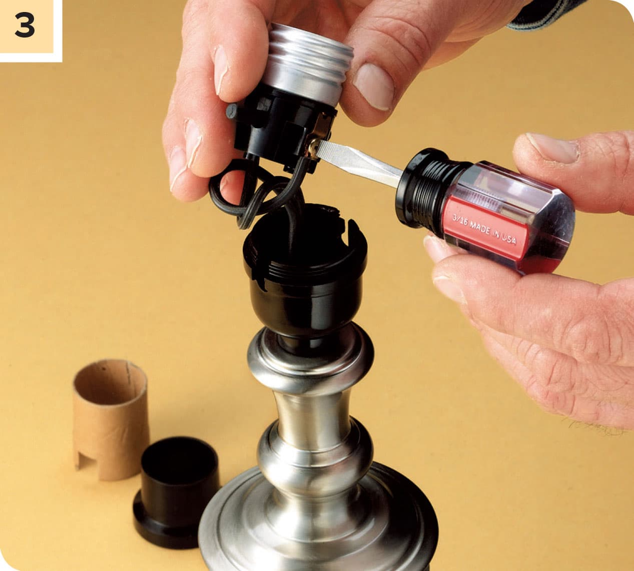
With the shell and insulation set aside, pull the socket away from the lamp (it will still be connected to the cord). Unscrew the two screws to completely disconnect the socket from the cord. Set the socket aside with its shell (you’ll need them to reassemble the lamp).

Remove the old cord from the lamp by grasping the cord near the base and pulling the cord through the lamp.
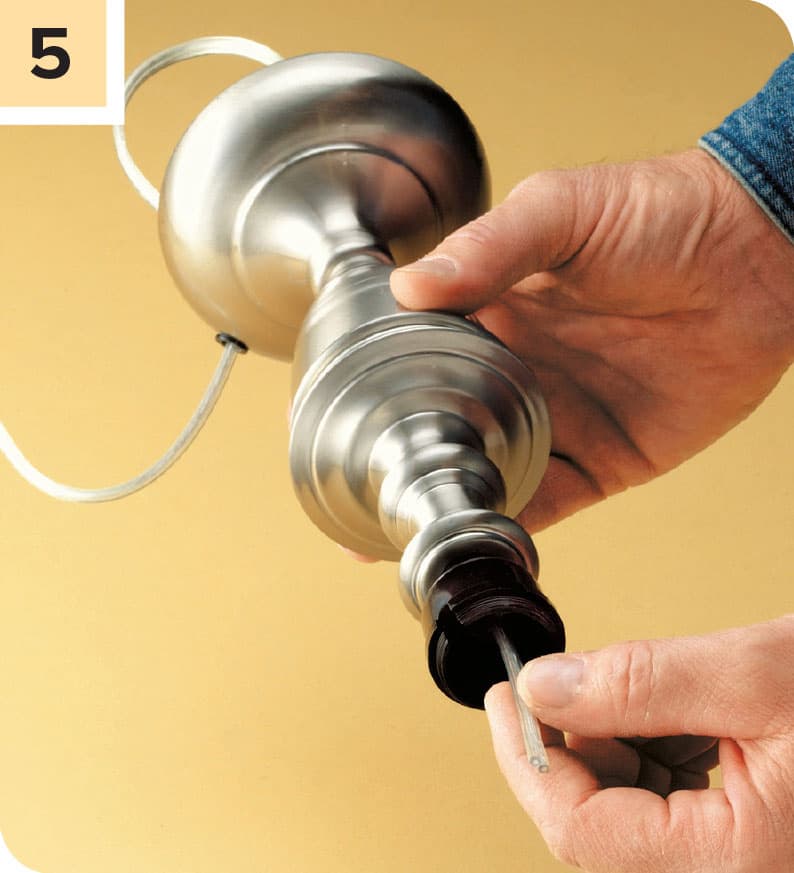
Bring your damaged cord to a hardware store or home center and purchase a similar cord set. (A cord set is simply a replacement cord with a plug already attached.) Snake the end of the cord up from the base of the lamp through the top so that about 3" of cord is visible above the top.

Carefully separate the two halves of the cord. If the halves won’t pull apart, you can carefully make a cut in the middle with a knife. Strip away about 3/4" of insulation from the end of each wire.

Connect the ends of the new cord to the two screws on the side of the socket (one of which will be silver in color, the other brass colored). One half of the cord will have ribbing or markings along its length; wrap that wire clockwise around the silver screw, and tighten the screw. The other half of the cord will be smooth; wrap it around the brass screw, and tighten the screw.
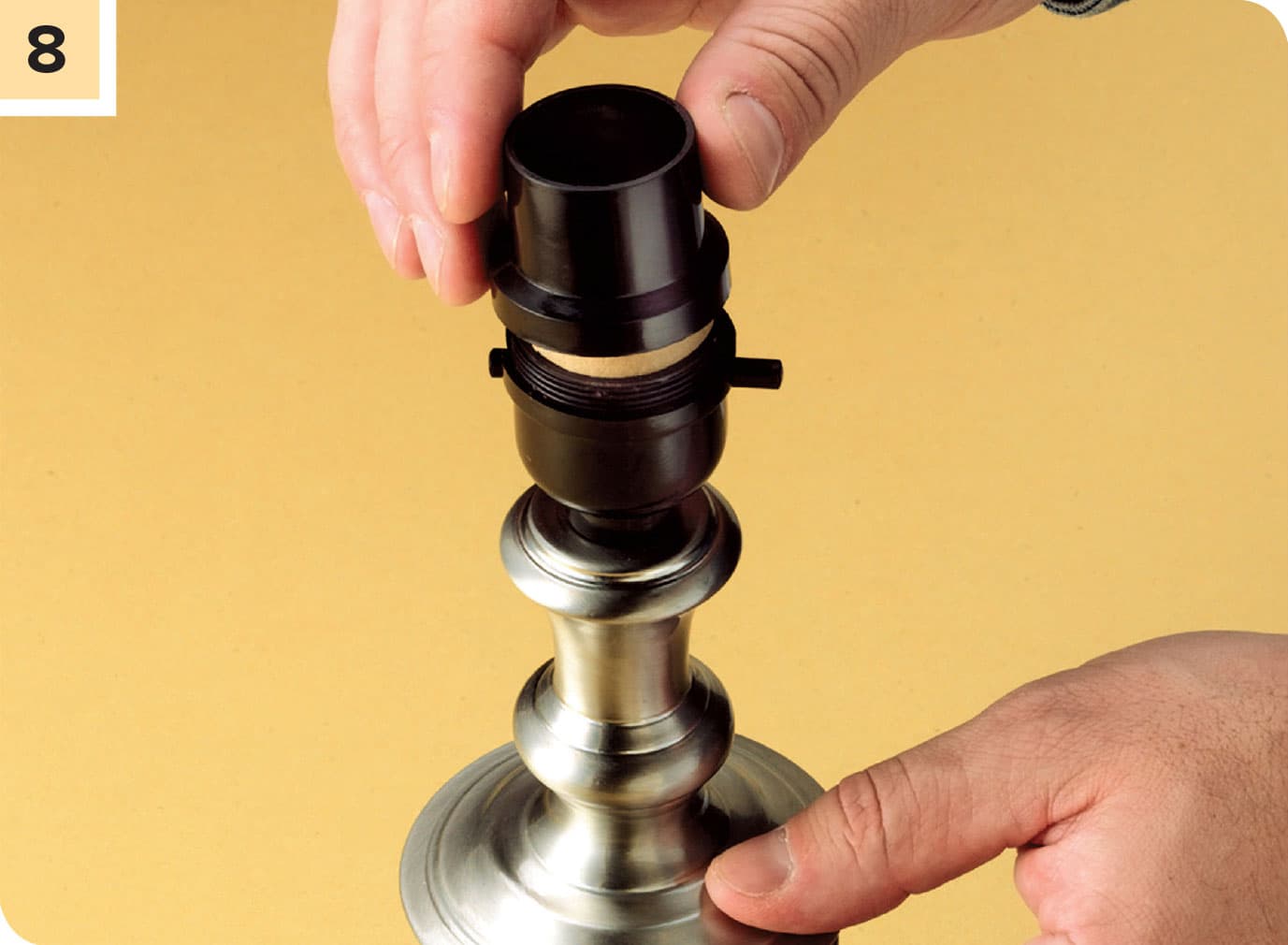
Set the socket on the base. Make sure the switch isn’t blocked by the harp—the part that holds the shade on some lamps. Slide the cardboard insulating sleeve over the socket so the sleeve’s notch aligns with the switch. Now slide the outer sleeve over the socket, aligning the notch with the switch. It should snap into the base securely. Screw in a lightbulb, plug the lamp in, and test it.