CHAPTER 2
Supplies, Techniques, and Fabrication Machines
THIS CHAPTER PROVIDES A BRIEF INTRODUCTION TO SEWING SUPPLIES AND TECHNIQUES AND an overview of basic electronic components and techniques. It also provides necessary information on computer-aided design/computer-aided manufacturing (CAD/CAM) and using laser cutters, 3D printers, and microcontrollers.
Once you learn to sew, the clothing you can create is limitless. We will be using hand sewing to sew electronic components onto garments and also machine sewing to construct garments, bags, and accessories. If you are new to hand or machine sewing, you may want to watch some introductory How to Sew videos on YouTube and consult your sewing machine manual before you get started. The fabric that you use to make clothes or accessories should be washed and ironed before you cut it out and use it for your project.
Sewing Supplies
Fabric Scissors
Fabric scissors are usually metal and have blades that are between 5 and 8 inches long. Try not to cut paper with your fabric scissors because paper will dull the blades.
Pins
Straight sewing pins will help keep your fabric pieces together as you sew by hand or with a sewing machine. Safety pins can also be used to help keep your projects together while you are working on them.

Figure 2.1 Basic sewing supplies (from left to right): scissors, sewing needles, pins, seam ripper, awl, thread, measuring tape, and ruler (top).
Sewing Needles
Hand sewing needles come in a variety of sizes. Use finer needles for lighter fabrics and thicker needles for heavy fabrics. A size 7 needle should be appropriate for most projects in this book. A large-eye needle should be used for sewing conductive thread because the thread is thick.
Thread
All-purpose polyester thread should be used to construct the garments and accessories.
Seam Ripper
This small tool has a sharp edge that rips out stitches.
Measuring Tape
A flexible measuring tape will help you measure your waist and chest to decide which size to make. If you don’t have a measuring tape, you can use a piece of string and measure it with a ruler.
Ruler
A clear, bendable 18-inch ruler will make measuring and marking very easy.
Awl
A sewing awl has a sharp point that makes a hole in fabric by spreading fibers apart instead of cutting. This will help to ensure that your fabric doesn’t unravel.
Leather Needle
This is a special sharp needle with a triangular point for sewing through leather. Leather needles can be purchased at leathercraft stores, many major craft stores, and some hobby stores.
Iron
A basic iron that can press natural and synthetic fabrics will help flatten seams and keep your project neat as you sew.
Sewing Machine
A sewing machine that can do a straight stitch, a zigzag stitch, and a backstitch will allow you to sew every project in this book. An 80/12 ballpoint needle should be used for T-shirt knits, a heavier 100/16 or 110/18 needle is used for fabrics such as canvas or denim, and a medium-sized 90/14 needle is appropriate for most woven garment fabrics. A serger is a specialized sewing machine that makes an overlock stitch and a coverstitch, like the seams and hem on your T-shirt. A serger is not necessary for the projects in this book but may be used if you have one.
Hand and Machine Stitches
Running stitches and whipstitches are the primary stitches we will use for our projects. All hand stitching starts by threading a needle and knotting the far end of the thread so that it can’t be pulled all the way through the fabric. A running stitch is used to sew two pieces of fabric together. You create it by inserting a needle into and out of the fabric several times in a line of small stitches (about ⅛ to ¼ inch long). A whipstitch is used on buttonholes to help keep the fabric from unraveling and can also be used to sew electronic components and covers onto fabric. Push the needle through the fabric near the edge. Wrap the thread around the edge of the fabric, and push the needle through again next to your first stitch. This technique will also be used to sew components onto the fabric. Take a small stitch completely through the front and back of the fabric. Wrap the thread around the component or cover, and then take another stitch completely through the fabric. Use more stitches until the component is securely attached. Then knot the thread to finish (Figure 2.2).

Figure 2.2 Hand-sewing techniques (from left to right): running stitch, whipstitch on edge, and whipstitch attaching components to fabric.
The machine stitches we will use are the straight stitch, the zigzag, and the backstitch. Straight stitches are the basic stitch used to join two pieces of fabric together. A zigzag stitch moves the needle left and right as you sew. It has more elasticity and is used for sewing seams on knits. It can also be used to help keep fabric edges from unraveling. A backtack, or small backstitch, is the small stitch forward and back that you should use at the beginning and end of every seam in order to keep your sewing from coming undone (Figure 2.3).
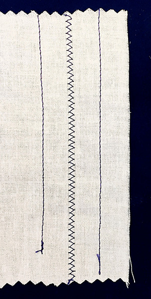
Figure 2.3 Machine sewing techniques (from left to right): straight stitch, zigzag stitch, and straight stitch with a ½-inch seam allowance.
Your sewing machine manual is a good reference to learn how to do each of these stitches. A seam allowance is the correct distance from the edge of your fabric to place your seam. Most projects in this book will use a standard ½-inch seam allowance.
Patterns
The downloadable associated materials for this project include a raglan-sleeve T-shirt pattern and a backpack pattern that you will be able to print on paper using a home printer. If you are using 8½- × 11-inch paper, you may need to print several sheets and tape them together to get the full pattern piece.
The first step in making accurate garments is to carefully cut out the paper patterns. After cutting out the paper, spread your fabric on a hard, flat surface. Place all the paper pattern pieces on your fabric, paying attention to instructions such as “cut on fold” or “cut two.” Pin the paper pieces to your fabric to ensure that they will stay in place as you use scissors to cut the fabric pieces out along the lines of the paper pattern (Figure 2.4).
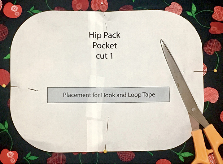
Figure 2.4 Paper pattern pinned to fabric before the fabric is cut out.
Electronic Tools and Components
Electronic tools and components are an important part of the fashion tech maker’s toolbox (Figure 2.5). While some of these tools and supplies may be available at local hobby shops and electronics supply stores, most will need to be ordered online. We have sourced the materials for these projects from well-known and reliable online stores, including Adafruit (www.adafruit.com), SparkFun (www.sparkfun.com), and Seeed Studio (www.seeedstudio.com).

Figure 2.5 Electronic tools and supplies.
Light-Emitting Diodes
A light-emitting diode (LED) lights up when current flows through it. LEDs are polarized, meaning that the current from your battery can only run through them in one direction, from the positive side (called an anode) to the negative side (called a cathode). In a simple LED with two legs, the longer side is the positive side; other LEDs may have the positive side marked with a plus (1) sign.
Addressable LEDs
LEDs can be individually set to a certain color by varying the levels of red, green, and blue light to make many different colors. These LEDs have a chip that receives commands from a controller, such as an Arduino. Addressable LEDs are available individually, on strips or rings, and as a matrix (Figure 2.6). Common versions are the WS2812B and also any with the brand name NeoPixel.

Figure 2.6 Simple LEDs and addressable LEDs are made individually, as strips or rings, and as a matrix.
Battery
Batteries store the energy used for electronic circuits. In this book we will use small coin cell batteries (CR2032), lithium polymer (LiPo) batteries, and large batteries that are commonly available as cell phone chargers. LiPo batteries are used a lot in wearable projects but can be dangerous if mishandled. Never pierce, bend, or overheat a LiPo battery because it can catch on fire.
Wire
Electrical wire has a conductive metal material on the inside to carry electric current and insulation and a nonconductive material on the outside. Solid-core wire is one solid strand of a particular gauge measured by the American Wire Gauge (AWG) standard. Stranded wire contains multiple strands inside the insulation and bends more easily. Silicone-covered wire is recommended for wearable projects because it is very flexible.
Solder
Solder is a metal alloy that is melted to create a bond between two pieces of metal. For these projects, we will be creating a bond between a wire and the electronic component with solder, and we will also be using through-hole soldering, which attaches components to a circuit board. Typically solder is 60 percent tin and 40 percent lead (60/40), although lead-free versions are also available.
Soldering Iron
A soldering iron is the tool that melts solder to join your components. For these projects, a soldering iron that is at least 25 watts (W) and has a small tip is recommended for detailed work and small connections.
Conductive Thread
This special thread is sewn by hand or with a sewing machine, but it can conduct electricity like wire. Conductive thread is usually stainless steel or silver metal that is bonded to nylon or another fiber. It can be purchased online from electronics suppliers.
Electrical Tape
Insulating tape is used to wrap wires to protect components. When taping wires, be sure that exposed wires aren’t touching other conductive surfaces.
Wire Cutter
This is a special tool used for cutting wires. Please note that cutting wire with scissors will dull the scissor blades.
Wire Stripper
This tool removes the plastic or silicone coating from electrical wires so that you can solder the bare wire underneath.
Safety Glasses
Always wear goggles or glasses when soldering because hot solder may splatter.
Helping Hands
Helping hands is a stand with multiple flexible clips that hold your components steady for soldering. This tool will be useful for some of the projects in the book that require soldering small boards and components.
Fiber Optics
These are thin, flexible fibers, usually made of glass or plastic, that transmit light. Fiber optics come as end-glow or side-glow fibers.
Microcontroller Boards/Arduino
A microcontroller board is an integrated circuit and supporting hardware that executes instructions typically for a specific process or set of devices. The Arduino is a common, inexpensive, easy-to-use open-source board. Other beginner and budget-friendly microcontroller boards for wearables are made by Adafruit, Sparkfun, Seeed Studio, and MakeFashion (Figure 2.7).
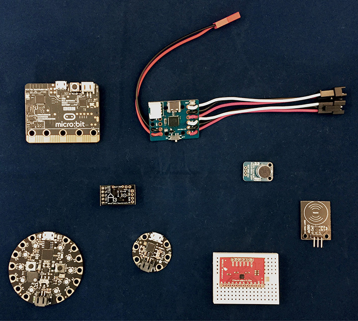
Figure 2.7 Microcontroller boards and sensors for wearable electronic projects.
Sensors
Sensors are electronic components that measure some aspect of the physical world. Sensors can sense such things as light, temperature, touch, and movement. In combination with microcontrollers, sensors can measure the physical environment and display the information in various ways, including lights, colors, and sounds.
Computer
A computer with an Internet browser will be needed to download project patterns and files and to access the programming interfaces and libraries for various microcontrollers. You may also need a computer to access CAD software for both laser cutting and 3D printing.
Electronic Techniques
Learning to make circuits and assemble electronics is an important skill set to acquire if you want to make your own wearable projects. Making a clean solder connection to connect wires together and soldering electronic components to a board are the most fundamental skills. There are many resources available from TAB Electronics at McGraw-Hill, including the Evil Genius series and Teach Yourself Electricity and Electronics, which will provide step-by-step projects to learn many electronics techniques. Watching online video tutorials and practicing with scrap wire and learn-to-solder projects are also great ways to build these essential skills.
To make the projects in this book, you will need to know how to solder wires together and also how to do through-hole soldering. Using a clean soldering tip, setting your soldering iron to a medium temperature (325–375 degrees Celsius), and wearing safety glasses are best practices. If you see smoke coming from your solder, try turning the temperature down or cleaning your tip using a brass sponge.
Soldering Wires Together
To prepare wire for soldering, you need to use your wire strippers to remove between ¼ and ½ inch of insulation on the end, leaving the wire inside intact. Using a hot soldering iron, tin the ends of the wire by adding a little hot solder to each wire individually. This will help them to bond more easily when you are ready to join them together. Next, hold the two pieces of wire close together using pliers or a helping hands clamp. Touch the tip of the soldering iron to the point on the wire that you would like to connect. Hold the solder so that it is touching both the tip of the soldering iron and the wire at the connection point. Once the solder starts melting, you can use the tip of the soldering iron to spread the melting solder over the connection point between your two wires (Figure 2.8).
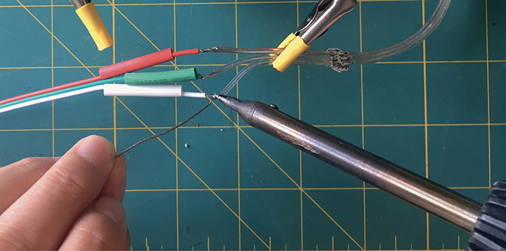
Figure 2.8 Soldering two wires together.
Through-Hole Soldering
The key to successful through-hole soldering is to heat the component, the board hole, and the solder at the same time. Insert the leg of your electronic component into the correct hole on the board. Touch the hot soldering iron tip to the board hole and the electronic component, and then add the solder until you see the solder start to melt. Once some solder has melted and stuck to the components, remove the rest of the solder and use the hot tip to melt the remaining solder through the hole and around the component leg. A good solder joint flows around the hole and the leg of the component, forming a little cone shape (Figure 2.9).

Figure 2.9 Through-hole soldering.
Sewing with Conductive Thread
Conductive thread can be sewn by hand using a regular sewing needle with a large eye. Because the thread can sometimes be a bit thicker than regular thread, you should cut the end you are threading at an angle, and you might want to use a needle-threader tool to help pull the thread all the way through. If you are sewing by hand, use a running stitch with the conductive thread to join your electronic components together through the fabric. Conductive thread is stiffer than regular thread and has more of a tendency to unravel. To keep your connections together, we recommend that you knot your thread, pass your knotted thread through the fabric, sew back through the thread just under the knot to secure it, and then start your stitching with several backstitches. To do a backstitch, you pass your knotted thread through the fabric and take two forward running stitches. You then take one stitch backward in between your two running stitches. Then take two more running stitches and backstitch again before continuing on with a regular running stitch (Figure 2.10). Adding a small dot of fabric glue, Fray Check, or clear nail polish to the knot can also help to keep your knots in conductive thread tight.
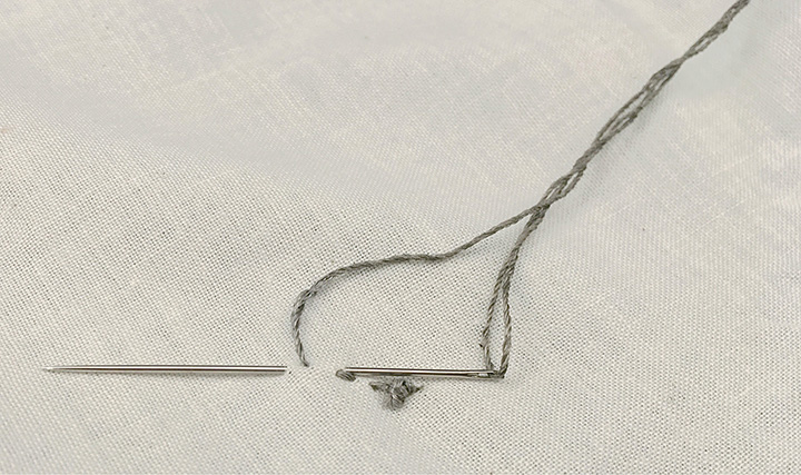
Figure 2.10 Backstitch with conductive thread by taking two running stitches and one backstitch.
When sewing conductive thread to electronic components, it is important to get a good connection to the copper. First, pass your knotted thread through your fabric, and make one full backstitch to secure it. Then whipstitch tightly around the copper pad several times, even tying a small knot before continuing with your running stitch. To reduce the strain on your conductive thread, we recommend that you attach sewn components using a whipstitch with regular thread in addition to the conductive thread (Figure 2.11). Because conductive thread is not insulated, it is easy to accidentally create shorts by crossing the lines of the conductive thread. Carefully plan your sewing so that you don’t have to cross lines of stitches, and when cutting knots, be certain that you aren’t leaving long tails that could touch other conductive parts of the project.
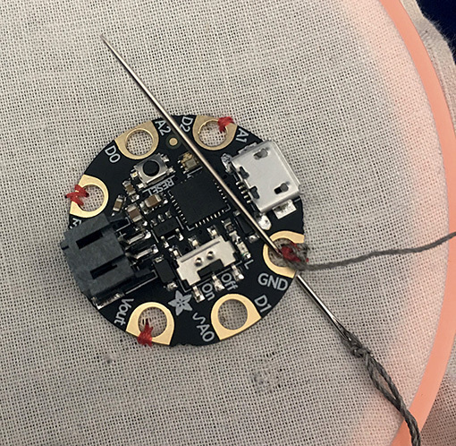
Figure 2.11 Wrap conductive thread tightly around a component with a whipstitch.
Microcontroller Boards
Microcontroller boards are the heart of interactive wearable projects. These boards typically perform one specific job using sensors, lights, or other inputs and outputs. Microcontrollers can do complex jobs, such as running a robot, but they depend entirely on the instructions you program. One of the most well-known boards is the Arduino (www.arduino.cc). This board is intended to be a learning tool, and the circuitry and design are open source, meaning that anyone can copy, modify, and sell circuit designs based on the original design. An all-in-one programming tool, the Integrated Development Environment (IDE), is typically used to program the Arduino and boards that are based on the Arduino. Because the design is so popular, there are fantastic resources available for learning how to program using the Arduino IDE.
Other easy-to-learn microcontroller boards, such as the micro:bit and Adafruit’s Circuit Playground Express, use visual block programming to tell your board what to do. We will be using Microsoft MakeCode (makecode.com) for visual block programming. MakeCode has a growing number of microcontroller boards that can be used and a well-organized website with tutorials and learning resources.
Another increasingly common programming language for wearable projects is MicroPython, based on the popular programming language Python. The advantage of MicroPython is that it is easy to get started on low-cost microcontroller boards, and it does not require some extra download steps that are needed on some very small Arduino boards. CircuitPython is an extension of MicroPython with support for Adafruit products. We’ve provided programming shortcuts for the projects as downloads to get you started, but once you learn the methods, your creativity is unlimited.
Laser Cutters
A laser cutting machine works by directing a beam of focused light that is capable of cutting through a variety of materials (Figure 2.12). This computer-controlled beam allows for precision cutting and fine etching on thin materials, usually up to ¼ inch thick. The most common laser cutters use a carbon dioxide (CO2) laser that burns and vaporizes to etch and cut through material. Natural and polyester fabrics, leather, thin wood, felt, acrylic, and many other materials can be cut on CO2. Most readily available lasers cannot cut metals, glass, or potentially toxic materials such as vinyl and polyvinyl chloride (PVC).

Figure 2.12 Laser cutters can cut and finely etch thin materials.
Laser cutters can commonly be found at makerspaces and increasingly at colleges, schools, and libraries. There are even desktop laser cutters for home use made by a number of companies, including Epilog, Orion, and Glowforge. If you don’t have a laser cutter available to you, there are local and online services, such as Ponoko (www.ponoko.com), that you can hire to cut your material from a computer file that you provide. An online search should locate makerspaces and custom cutting services in your area. You will usually be required to take a safety class before operating a laser cutter at a shared space. Always carefully follow the instructions and materials restrictions for the laser you are operating. Operating a laser incorrectly can quickly start fires or release toxic gases.
Laser Cutting Supplies
Natural and Manufactured Fabrics
Natural fabrics such as cotton, wool, and linen can all be cut with most lasers. Polyester, nylon, and other synthetic fabric blends cut well with slightly melted, sealed edges; some makerspaces may have restrictions on laser cutting synthetic fabrics. Both wool felt, and wool and synthetic blend fiber felt can be cut with a laser cutter. Do not cut fabrics with PVC because doing so can release toxic gases and also harm laser components.
Leather
Vegetable-tanned leather is an excellent material for laser etching and engraving. Some faux leathers or “vegan” leather contain PVC and should not be cut with a laser cutter.
Acrylic
Acrylic is a common plastic that is also known as Lucite, plexiglass, or Perspex. Acrylic comes in cast or extruded sheets, and ¼-inch thickness is a common size for laser-cut projects.
Design for the Laser
CAD software can create two-dimensional (2D) drawings or three-dimension (3D) models. When cutting material on a laser cutter, the machine is using a 2D vector graphic format. There are many pieces of software that can produce such files, including Inkscape (free and open source), Adobe Illustrator, CorelDRAW, and AutoCAD. Vector files usually have a file extension of .ai, .svg, .eps, .dxf, or .dwg. Which extension you will use depends on your laser cutter software; most CAD software will be able to convert or export vector files to different types. To get you started, the vector files for projects in this book are available as a download. Once you are comfortable using a specific CAD software, you can use the downloadable project files as a starting place to experiment and create personalized designs for electronics projects.
3D Printing
3D printing is a manufacturing process that makes a three-dimensional object from a digital design file by adding material together. By using a 3D printer, you can rapidly make individual, personalized parts for projects and also try out new designs without having to order many pieces from a commercial supplier. The most common home machines use very thin layers of plastic to slowly build a solid object. This is commonly called fused-filament fabrication because the printers use a roll of plastic filament as the construction material (Figure 2.13). Other 3D printing processes are resin printers, which can be found at professional printing services or in specialty home machines. Resin printers use photopolymerization (which uses light to cure a liquid resin) to create a 3D object or granular materials binding (which use lasers or other energy sources to fuse layers of powder together).
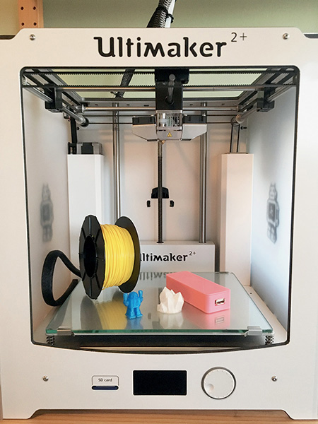
Figure 2.13 Filament 3D printer, filament roll, and printed objects.
3D printers are available at many makerspaces, public libraries, and schools; there are also online services, such as Shapeways (www.shapeways.com) that will 3D print your object in a variety of different materials. Most shared makerspaces will require a safety and basic-use class before you are cleared to use the 3D printer. We recommend that you use polylactic acid (PLA) filament for the projects in this book because it is widely available in many fantastic colors (even metallic and glow-in-the-dark filaments) and can be used in a wide variety of printers. PLA filament is also affordable and easy to use for beginning makers, and it is a bioplastic, meaning that it is made from renewable plant resources. If you can’t purchase 3D filament from your makerspace, you can buy it online via some 3D printer manufacturers’ websites and 3D printing supply sites such as MatterHackers (www.matterhackers.com). When choosing a personal 3D printer, you will want to consider the types of plastic filaments you want to use, the size of your print, print quality, and, of course, price. Make: magazine (makezine.com) publishes an annual review of 3D printers that can guide you in purchasing the perfect 3D printer for your needs.
3D Design and Printing
There are many different 3D modeling tools you can use to create original designs or to modify existing 3D models. Like 2D designs, these tools use CAD to produce a digital file. Some common software programs for 3D design include Tinkercad and Morphi App, which are great for beginners, and Blender and Fusion 360, which have more functionality once you learn the basics. All these programs have online tutorials and videos that will help you to get started making 3D designs.
The easiest way to get started with 3D design for printing is to look at the many existing designs already available online. You can download 3D designs from Thingiverse (www.thingiverse.com) and YouMagine (www.youmagine.com), which have thousands of free 3D designs. Experimenting with existing files will help you understand the capabilities of your printer and can also provide a base model to remix for building your own projects.
Using Tinkercad
Tinkercad (www.tinkercad.com) is a free browser-based 3D design and modeling tool. Tinkercad is very intuitive and easy to learn, especially if you don’t have much experience with these tools. If you already have a favorite 3D design and modeling tool, you can use that.
Working in Tinkercad is easy. You can easily create simple designs using shape and text generators. If you don’t already have a Tinkercad or Autodesk account, you will first need to create one.
Before you start designing, change the dimensions of the work plane to match either the size of the printer bed or, if the piece is larger than the printer bed, the size printing. You can change the work-plane dimensions by clicking “Edit Grid” in the lower left of the main Tinkercad view (Figure 2.14). You can also change the units in which dimensions are displayed.

Figure 2.14 Edit “Grid properties” to resize your work plane to match the size of your printer or pattern piece.
Tinkercad gives each new design a whimsical name; you can change the name by clicking on the name in the upper right-hand corner.
Slicing with Cura
Once you are satisfied with your design, it’s time to prepare the design for printing. First, export the design as an .stl file. In Tinkercad, the Export button is on the right-hand side of the toolbar. In order to print the design, you will have to translate the geometry of the model into commands that the printer can understand. This is usually referred to as slicing. 3D printers lay down a single 2D layer of melted plastic at a time. Adding additional layers on top of the first builds up the design in three dimensions. The layers are typically in the 0.06- to 0.15-millimeter range depending on the capabilities of the printer.
Slicing is the automated process of breaking a model into a series of thin layers and creating the machine control instructions for each layer. There are a number of 3D printer slicing apps. For these projects, we will be using Cura 3.3, a free and open-source slicer that works with many 3D printers (Figure 2.15).
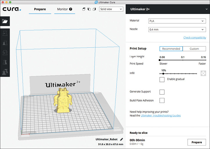
Figure 2.15 Slice your 3D models with Cura for 3D printing.
Downloadable Files for This Book’s Projects
The projects in this book have sewing patterns, laser-cutter designs, 3D design files, and program files available as downloads from the publisher’s website. Sewing patterns have a file extension of .pdf and can be printed on regular 8½- × 11-inch printer paper. Designs that can be cut and etched on a laser cutter have a file extension of .svg. These can be read with most laser-cutter software as well as 2D design software. The 3D design files have an extension of .stl. 3D design models are also available on Thingiverse (www.thingiverse.com/amped_atelier/designs) and YouMagine (www.youmagine.com/amped_atelier/designs), or you can have the models printed by Shapeways (www.shapeways.com/designer/amped_atelier/creations).