
CHAPTER 6
Solar Backpack
HARNESS THE POWER OF THE SUN WITH THIS PERSONALIZED SOLAR BACKPACK THAT WILL KEEP your mobile devices charged.
What You Will Learn
In this chapter, you will learn
 The basics of photovoltaics
How to put together a solar charger from existing subsystems
How to construct a backpack
Files You Will Need
Backpack pattern: backpackPattern.pdf
Tools You Will Need
Sewing machine and thread
Soldering tools: soldering iron, solder
Basic electronics tools
Materials You Will Need
Large 6-volt (V), 3.5-watt (W) solar panel (www.adafruit.com/product/500)
USB/solar lithium ion/polymer battery charger (www.adafruit.com/product/390)
Lithium ion/polymer battery: 3.7 volts (V), 1,200–2,500 milliampere hour (mAh)
3.5/1.3- or 3.8/1.1- to 5.5/2.1-millimeter DC jack adapter cable (www.adafruit.com/product/2788)
Adafruit PowerBoost 500 Basic (www.adafruit.com/product/1944)
High-temperature polyimide tape (www.adafruit.com/product/3057)
1 yard of 45-inch or ¾ yard of 60-inch outdoor fabric, canvas, denim, or other sturdy fabric
½ yard of contrast-colored outdoor fabric, canvas, denim, or other sturdy fabric for top flap
¼ yard of lightweight iron-on interfacing
2 yards of 1-inch-wide webbing or belting
2 yards of ¼-inch cord or similar thin ribbon
One 1-inch quick-release clip or parachute clip
Four D-rings of 1-inch diameter (Note: The diameter of the D-rings should match the width of the straps.)
No-sew option: Purchased backpack with a fabric or canvas top flap measuring at least 10 inches × 6 inches
Our four main electronics components in this project are the solar panel to convert light into electricity, the solar charger to regulate and manage charging a battery, a battery to store that electricity, and the power boost to charge our phone (Figure 6.1). The solar panel and solar charger for this project should only be used with 3.7-/4.2-volt (V) lithium ion/polymer battery. The solar charger features smart load sharing to automatically use the input power, when available, to keep the battery from constantly charging/discharging.
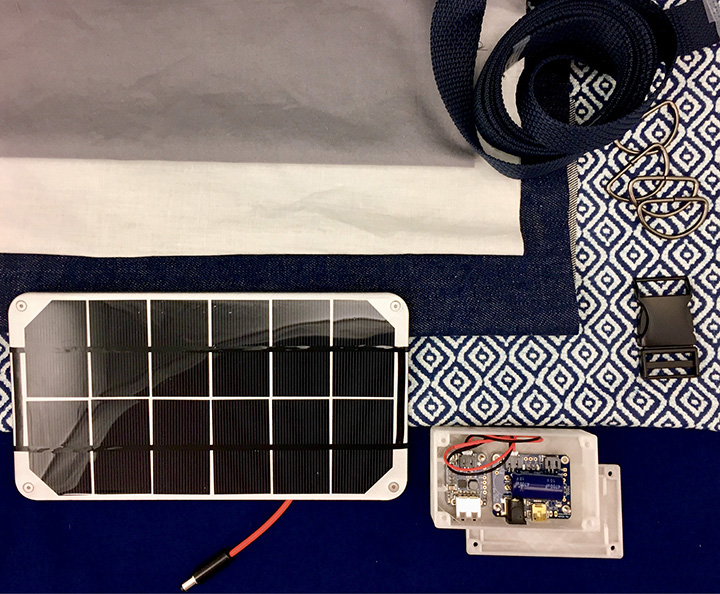
Figure 6.1 Solar backpack supplies.
There are a couple of things to remember about working with solar chargers. First, don’t leave the batteries in direct sunlight or in very hot places, like a car dashboard, because this will damage the battery and reduce the battery life! Second, solar panels work best in direct sunlight. Any covering, including glass, plastic, or shade, will decrease the efficiency of the panel. We’ll be mounting our panel on the outside of the backpack to get the best access to the sun.
Step 1: Prepare the Solar Charger
The Adafruit USB, DC & Solar Lipoly Charger comes assembled with all its components except for the large filtering electrolytic capacitor. Our first step is to solder the capacitor to the solar charger. Capacitors are polarized, so check the polarity of the capacitor to make sure that the positive lead of the capacitor goes into the pad marked with the plus sign (+). If you want, you can bend the capacitor over a bit as well, but don’t have it touch the hot charging chip, the black square in the middle of the printed-circuit board (Figures 6.2 and 6.3). Cover the charging chip with high-temperature polyimide tape, sometimes referred to by its color and the brand name as yellow Kapton tape. Polyimide is both electrically isolating and can withstand high temperature.
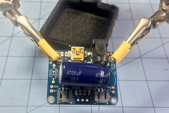
Figure 6.2 Mount the capacitor parallel to the charger board. Remember, the capacitor is polarized, so check the polarity.
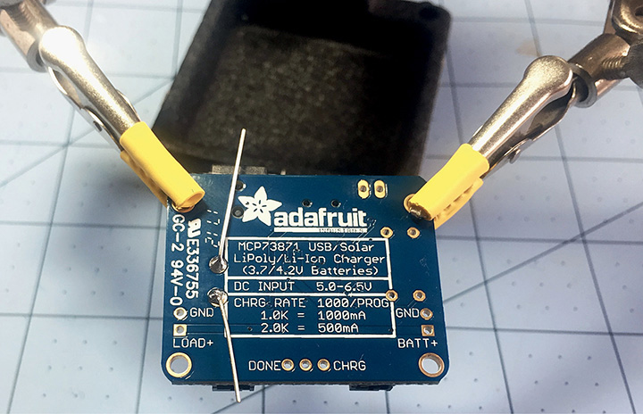
Figure 6.3 Solder the leads of the capacitor to the charger board.
Step 2: Prepare the Solar Panel
If the power connector of the solar panel doesn’t fit into the DC jack of the solar charger, you will need to either swap out the DC plug or, if the solar panel came with a 1.1-millimeter plug, use the 3.5 to 3.8/1.1- to 5.5/2.1-millimeter DC jack adapter cable (www.adafruit.com/product/2788). The solar charger DC jack accepts a 5.5-millimeter-long and 2.1-millimeter-diameter plug. Let’s go over swapping the plug.
1. Snip off the connector, and then strip off the outer casing (Figure 6.4).
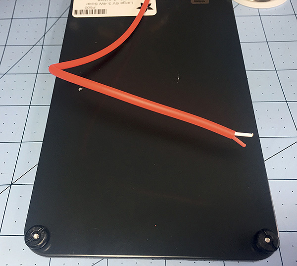
Figure 6.4 If you need to swap the solar panel power connector, snip off the connector and then strip off the outer casing.
2. Solder the 5.5/2.1-millimeter barrel connector (www.adafruit.com/product/3310) to the striped power cable. Strip the outer sleeve of the power connector to reveal the red and black wires. Strip and tin these wires, and then solder the red wire to the center connector and the black wire to the ring of the jack (Figure 6.5).
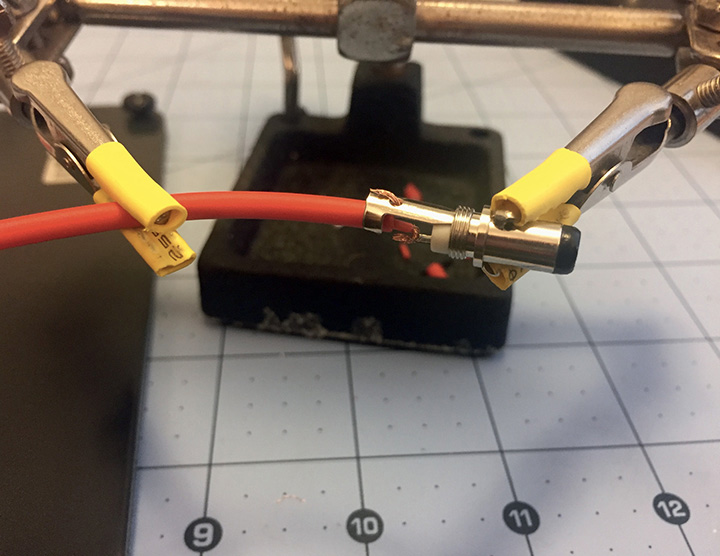
Figure 6.5 Solder the red wire to the center connector and the black wire to the ring of the jack.
Step 3: Solder the USB Connector on the Power Boost 500
The Power Boost 500 comes assembled, except for the USB plug. Solder the USB plug to the Power Boost 500 board.
Step 4: Splice Two JST-PH Connectors End to End
A short connector cable can be used to connect the solar charger to the Power Boost 500. Using a cable instead of soldering connections between components allows you to swap and replace components easily.
1. Strip about ¼ inch of wire from each wire on the two JST-PH plug connector cables.
2. Slip some heat-shrink tubing over the wires of one connector.
3. Connect the red wire of one cable to the red wire of the other cable by wrapping the bare wires together (Figure 6.6).

Figure 6.6 Splice two JST-PH cables to create a connection cable.
4. Solder the red wires, and repeat for the black wires.
5. Move the heat shrink into place, and apply heat (Figure 6.7).
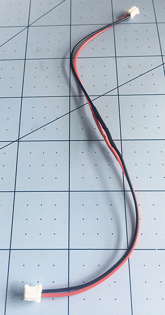
Figure 6.7 The completed cable with a JST-PH plug connector on both ends.
Step 5: Hook Everything Up
The central electrical component of this project is the solar charger. The solar panel plugs into it using the power jack labeled “DC IN.” The battery plugs into it at the “BATT” socket. The Power Boost 500 is connected to the solar charger’s “LOAD” socket via the connection cable (Figure 6.8).
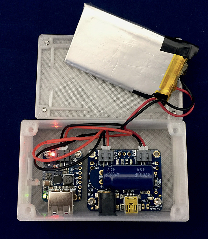
Figure 6.8 The battery connects to the BATT socket on the solar charger. The Power Boost 500 connects to the LOAD socket on the solar charger.
When you plug in the solar panel, look for the red power-indicator light-emitting diode (LED) labeled “PWR” located near the Micro B USB port. If it turns on, the panel is providing power. If the battery is charging, the orange LED will turn on. When the battery is fully charged, the green LED will turn on. Both of these LEDs are located between the BATT and LOAD sockets.
Step 6: Make the Backpack
Sew the backpack out of a sturdy canvas, denim, or outdoor fabric. Remember to backtack when stitching at the start and stop of all your sewing. For a no-sew option, purchase a simple backpack with a large top flap, and skip to the next step to attach your solar panel to the bag.
1. Cut out your back and front pieces, the two flap pieces, the pocket, and the two interfacing flap pieces.
2. Fuse the iron-on interfacing to the flap pieces. This will make the flaps stiffer and a better surface for mounting the solar panel (Figure 6.9).
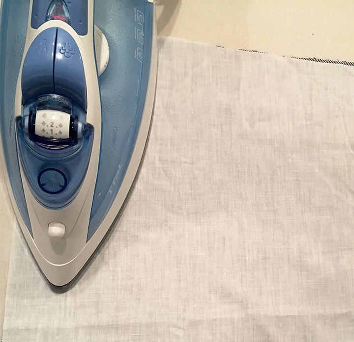
Figure 6.9 Using an iron, fuse the interfacing to the fabric flaps.
3. Construct the interior pocket first. Make a hem on the top by turning ¼ inch on the upper edge of the pocket in to the wrong side and press, turn in again ½ inch, and sew it down to finish the top edge.
4. Press the sides and bottom of the pocket ½ inch in to the wrong side.
5. Pin the wrong side of the pocket to the wrong side of the back piece at the placement line approximately 4 inches from the top with the folded edges of the pocket facing in.
6. Stitch the pocket onto the back piece by sewing the sides and lower edge of the pocket close to the folded edge (Figure 6.10).
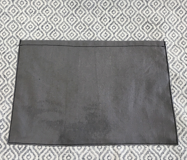
Figure 6.10 Sew the pocket onto the wrong side of the back piece.
7. Cut one piece of webbing 5 inches long, fold the end over ¼ inch, then ¼ inch again, and sew it with a straight stitch to make a nice, neat hem (Figure 6.11). We will put the hemmed end of the webbing through the prong side of the quick release clip in a later step.
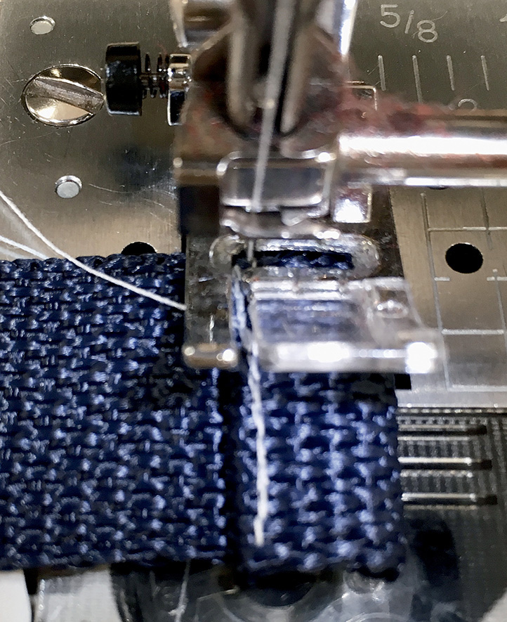
Figure 6.11 Fold the edge twice, and sew it with a straight stitch to hem the webbing.
8. Pin the other end of the webbing piece you just sewed to the lower end of one flap section with wrong sides up and raw edges of webbing and flap even. Pin to hold the webbing in place (Figure 6.12).
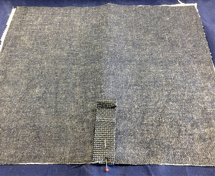
Figure 6.12 Pin the edge of the webbing inside the flap.
9. Place the top flap pieces with their right sides together. The webbing should be sandwiched in between the flap pieces. With the right sides together, stitch the top flap sections together at the sides and lower edge. Trim the lower corners to make it easier to turn with thick fabric (Figure 6.13).
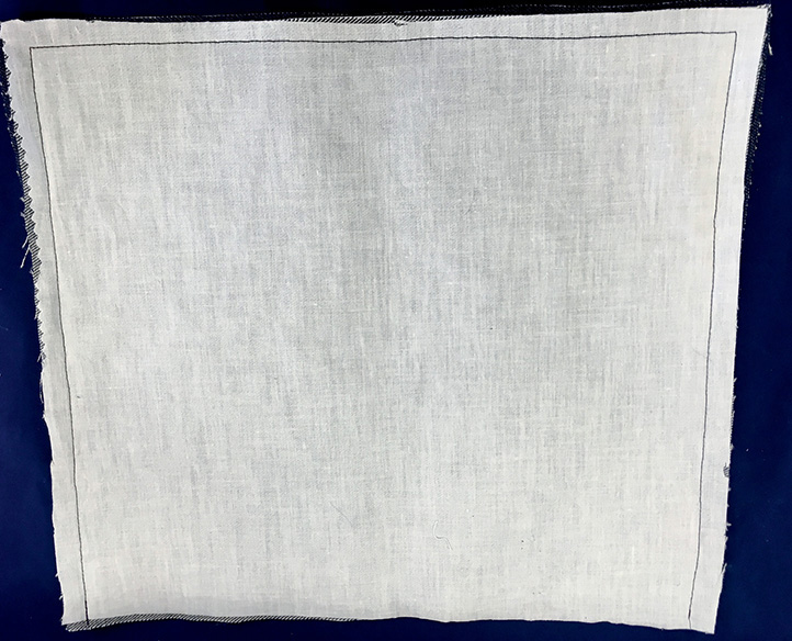
Figure 6.13 Sew the sides and lower edge of the flap.
10. Turn the top flap right side out, and press with an iron. The webbing should now be part of the flap and right-sides out. The top of the flap is still open. Turn the open edges in ½ inch to face each other and pin them closed. Topstitch ⅛ inch around flap (Figure 6.14).
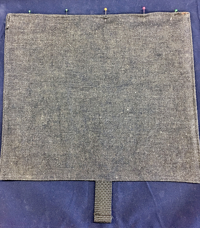
Figure 6.14 Turn the open edges in ½ inch, and topstitch all the way around the flap.
11. Pin the flap to the back piece with the flap extending off the top of the back, along the line labeled “placement line for flap” on the pattern. Sew the flap to the back piece by stitching over the topstitching from the last step. After sewing the flap to the top back, insert the hemmed end of the webbing strap into the pronged end of the quick release clip.
12. Cut two pieces of webbing, each 12 inches long. On each piece, turn in ¼ inch on one end of the webbing piece, and press it with an iron. Turn in ¼ inch again and press. Stitch close to the inner pressed edge to make a neat hem.
13. Turn 1 inch on the lower end of the webbing piece to the opposite side and press. Do not sew it down. These will be the bottom backpack straps
14. Place the lower end of the webbing in the lower placement squares on the back piece with the 1-inch ends facing into the fabric. Stitch over the ends securely in a box and X shape, as shown (Figures 6.15 and 6.16).
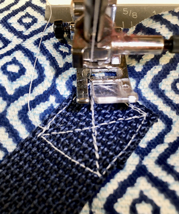
Figure 6.15 Sew the straps securely to the backpack by stitching along an X and box shape.

Figure 6.16 Attach the back straps in the placement boxes on the back piece of the backpack.
15. Cut two pieces of webbing, 14 inches long. Fold one end of each over ¼ inch, then ¼ inch again, and then sew them with a straight stitch to make a nice, neat hem. Insert one end of each through the two D-rings. Fold the end down 1 inch, and stitch it closed close to D rings. Turn 1 inch on the lower end of the webbing piece to the opposite side and press. These are now the top straps
16. On combined back and flap pieces, place the lower end of the top strap webbing on the placement markings on the flap. Stitch it securely in a box and X shape as in step 14 (Figure 6.17).

Figure 6.17 Sew the top straps to the flap in the placement boxes.
17. Cut one piece of webbing 10 inches long. Fold one end over ¼ inch, then ¼ inch again, and then sew with a straight stitch to make a hem. The hemmed end of the webbing will be used for the other side of the quick release clip. Fold 1 inch down, and stitch closed close to the clip.
18. Pin the unhemmed end of the webbing piece to the center bottom right side of the front piece with the raw edges of webbing and the front even. Pin to hold the webbing in place (Figure 6.18).

Figure 6.18 Attach the unhemmed side of the webbing to the center bottom of the front piece of the pack.
19. Pin the front to the back edges right sides together. The straps and the webbing piece should be sandwiched inside the bag. Sew along the bottom edge, and press the bottom seam open.
20. Fold the back and the front together again with the right sides together, and this time sew the front and back together at the sides, being careful to leave the small area between the arrows at the top open for inserting the drawstring later (Figure 6.19). Backtack on the seams where you are leaving space for the drawstring. Press the side seams open.
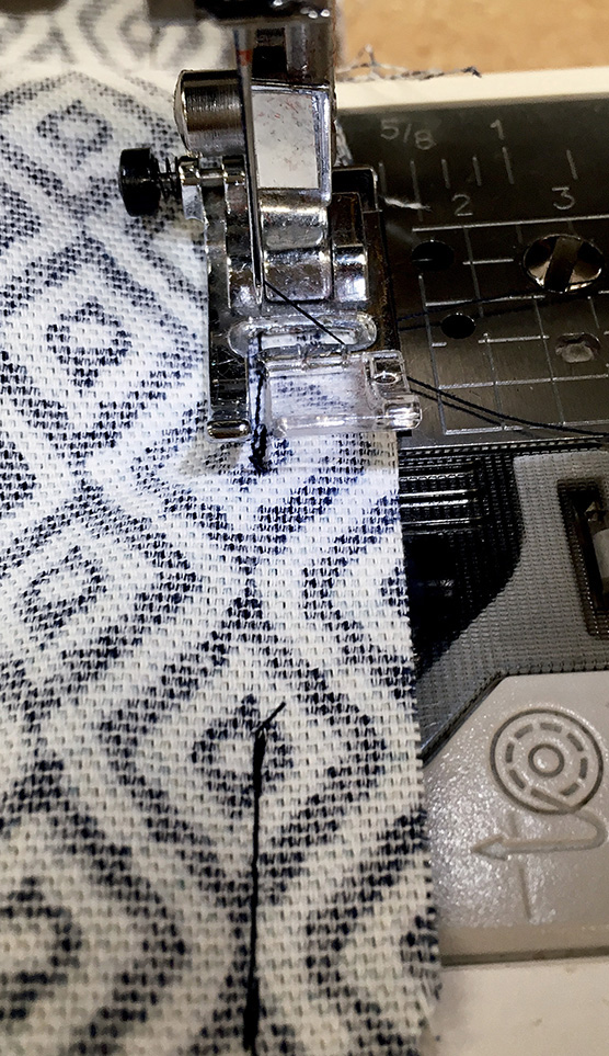
Figure 6.19 Sew the front and back pieces together along the side seams, leaving space for a drawstring.
21. Bring together the sides and bottom, matching seams. Sew across the edge to sew the corners closed on the bottom of the bag (Figures 6.20 and 6.21).
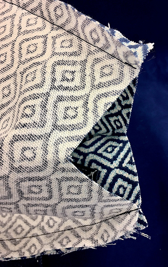
Figure 6.20 Bring the sides and bottom corners together, and sew across the edge to make the bottom corner of the bag.

Figure 6.21 Sew across the edge on the flattened corners.
22. Turn the whole bag right-side out. All the straps should now be on the outside.
23. Turn ¼ inch on the upper edge of backpack to the inside and press.
24. To form a casing for ribbon or cord, turn the edge inside again another inch and press; then stitch close to inner pressed edge (Figure 6.22).
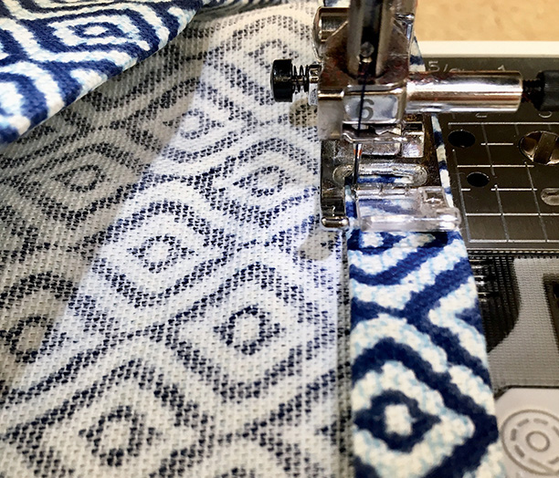
Figure 6.22 Fold the top edge in twice, and stitch to make a drawstring casing.
25. Cut two pieces of cord, each 36 inches long, and insert one all the way around the casing using a safety pin to help pull it through. Both ends of one cord should stick out through the same hole. Knot the ends together.
26. Insert the other cord through the opposite casing hole, and pull all the way around. Knot the ends of the cord together (Figure 6.23).
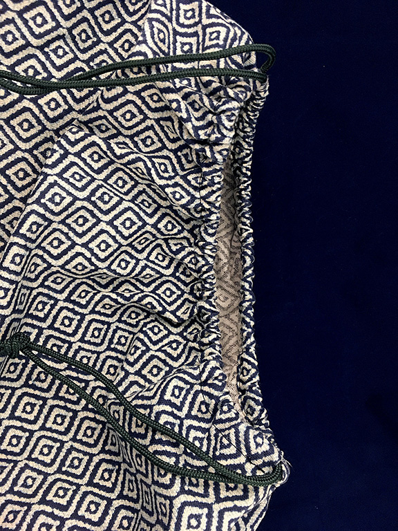
Figure 6.23 Use two lengths of ribbon or cord to make a drawstring closure around the top of the bag.
27. On the front of the backpack, insert the remaining side of the quick release clip through the hemmed end of the webbing and make sure that it can clip together with the prong end on the flap. On the back of the backpack, insert the lower straps through the D-rings and adjust to fit.
Step 7: Attach the Solar Panel to the Backpack
1. Lay the top flap of your backpack flat. Place the solar panel evenly on the flap with the wires extending down toward the back of the bag. We will make five holes in the top flap, four for each of the solar panel attachment points and one for the wires to go into the bag.
2. Using chalk or pencil, make small marks on the flap to show the edges of the solar panel and also where the four attachment points are.
3. Unscrew the ends of the solar panel attachments. Use an awl to make small holes all the way through the flap that these points will fit into. Using a small sharp pair of scissors or the awl, make a hole in the flap fabric inside the rectangle of the solar panel so that the wires can go inside the bag (Figure 6.24). You can whipstitch the edges of this cut to make it neater.
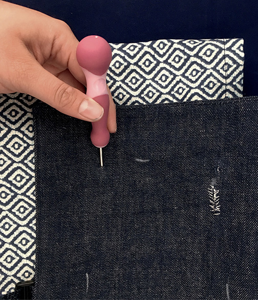
Figure 6.24 Use an awl or small, sharp scissors to make holes in the flap to attach the solar panel and place the wires inside the bag.
4. Insert the attachments points of the panel through the four holes in the flap, and screw the ends back on so that the solar panel is attached to the outside flap of the bag. Pull the connector wires through to the inside (Figure 6.25).
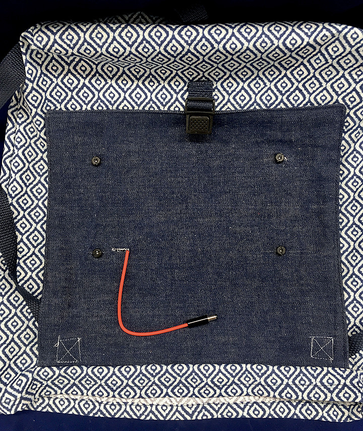
Figure 6.25 Insert the attachment posts through the holes, and put the screws on to hold the panel. Then pull the connector wires through the slit.
Step 8: Use It Outside
Place the electronics and your phone inside the pocket on the bag. Take the bag out to direct sunlight to charge your phone! Remember, the solar panel works best pointing toward the sun, preferably perpendicular to the sun. Caution: Solar panels can become hot when charging in direct sunlight. Moving the panel to shade or indoors should quickly lower the temperature if the panel ever becomes very hot.