switch statements are used by programmers (and malware
authors) to make a decision based on a character or integer. For example, backdoors commonly select
from a series of actions using a single byte value. switch
statements are compiled in two common ways: using the if style or using jump tables.
Example 6-20 shows a simple switch statement that uses the variable i. Depending on the value of i, the code under the
corresponding case value will be executed.
Example 6-20. C code for a three-option switch statement
switch(i)
{
   case 1:
      printf("i = %d", i+1);
      break;
   case 2:
      printf("i = %d", i+2);
      break;
   case 3:
      printf("i = %d", i+3);
      break;
   default:
      break;
}
This switch statement has been compiled into the assembly
code shown in Example 6-21. It contains a series of
conditional jumps between ❶ and ❷. The conditional jump determination is made by the comparison
that occurs directly before each jump.
The switch statement has three options, shown at ❸, ❹, and ❺. These code sections are independent of each other because of
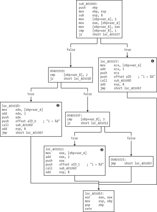
the unconditional jumps to the end of the listing. (You’ll probably find that switch statements are easier to understand using the graph shown in Figure 6-3.)
Example 6-21. Assembly code for the switch statement example in Example 6-20
00401013        cmp     [ebp+var_8], 1
00401017        jz      short loc_401027 ❶
00401019        cmp     [ebp+var_8], 2
0040101D        jz      short loc_40103D
0040101F        cmp     [ebp+var_8], 3
00401023        jz      short loc_401053
00401025        jmp     short loc_401067 ❷
00401027 loc_401027:
00401027        mov     ecx, [ebp+var_4] ❸
0040102A        add     ecx, 1
0040102D        push    ecx
0040102E        push    offset unk_40C000 ; i = %d
00401033        call    printf
00401038        add     esp, 8
0040103B        jmp     short loc_401067
0040103D loc_40103D:
0040103D        mov     edx, [ebp+var_4] ❹
00401040        add     edx, 2
00401043        push    edx
00401044        push    offset unk_40C004 ; i = %d
00401049        call    printf
0040104E        add     esp, 8
00401051        jmp     short loc_401067
00401053 loc_401053:
00401053        mov     eax, [ebp+var_4] ❺
00401056        add     eax, 3
00401059        push    eax
0040105A        push    offset unk_40C008 ; i = %d
0040105F        call    printf
00401064        add     esp, 8
Figure 6-3 breaks down each of the
switch options by splitting up the code to be executed from the next decision to be made. Three of
the boxes in the figure, labeled ❶, ❷, and ❸, correspond
directly to the case statement’s three different options. Notice that all of these boxes
terminate at the bottom box, which is the end of the function. You should be able to use this graph
to see the three checks the code must go through when var_8 is
greater than 3.
From this disassembly, it is difficult, if not impossible, to know whether the original code
was a switch statement or a sequence of if statements, because a compiled switch statement
looks like a group of if statements—both can contain a
bunch of cmp and Jcc
instructions. When performing your disassembly, you may not always be able to get back to the
original source code, because there may be multiple ways to represent the same code constructs in
assembly, all of which are valid and equivalent.
The next disassembly example is commonly found with large, contiguous switch statements. The compiler optimizes the code to avoid needing to make so many
comparisons. For example, if in Example 6-20 the value
of i were 3, three different comparisons would take place before
the third case was executed. In Example 6-22, we add
one case to Example 6-20 (as you can see by comparing
the listings), but the assembly code generated is drastically different.
Example 6-22. C code for a four-option switch statement
switch(i)
{
   case 1:
      printf("i = %d", i+1);
      break;
   case 2:
      printf("i = %d", i+2);
      break;
   case 3:
      printf("i = %d", i+3);
      break;
   case 4:
      printf("i = %d", i+3);
      break;
   default:
      break;
}
The more efficient assembly code in Example 6-23 uses a jump table, shown at ❷, which defines offsets to additional memory locations. The switch variable is used as an index into the jump table.
In this example, ecx contains the switch variable, and 1 is
subtracted from it in the first line. In the C code, the switch table range is 1 through 4, and the
assembly code must adjust it to 0 through 3 so that the jump table can be properly indexed. The jump
instruction at ❶ is where the target is based on the
jump table.
In this jump instruction, edx is multiplied by 4 and added
to the base of the jump table (0x401088) to determine which case code block to jump to. It is
multiplied by 4 because each entry in the jump table is an address that is 4 bytes in size.
Example 6-23. Assembly code for the switch statement example in Example 6-22
00401016sub ecx, 100401019 mov [ebp+var_8], ecx 0040101C cmp [ebp+var_8], 3 00401020 ja short loc_401082 00401022 mov edx, [ebp+var_8] 00401025 jmp ds:off_401088[edx*4]❶ 0040102C loc_40102C: ... 00401040 jmp short loc_401082 00401042 loc_401042: ... 00401056 jmp short loc_401082 00401058 loc_401058: ... 0040106C jmp short loc_401082 0040106E loc_40106E: ... 00401082 loc_401082: 00401082 xor eax, eax 00401084 mov esp, ebp 00401086 pop ebp 00401087 retn 00401087 _main endp 00401088 ❷off_401088 dd offset loc_40102C 0040108C dd offset loc_401042 00401090 dd offset loc_401058 00401094 dd offset loc_40106E
The graph in Figure 6-4 for this type of
switch statement is clearer than the standard disassembly
view.
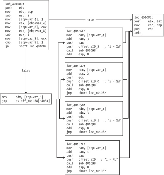
As you can see, each of the four cases is broken down clearly into separate assembly code chunks. These chunks appear one after another in a column after the jump table determines which one to use. Notice that all of these boxes and the initial box terminate at the right box, which is the end of the function.