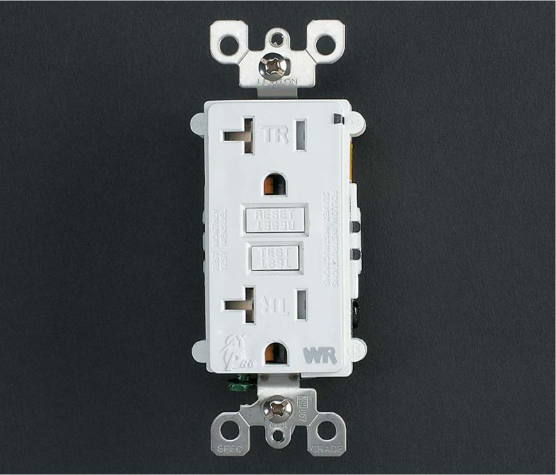
Modern GFCI receptacle have tamper-resistant slots. Look for a model that’s rated “WR” (for weather resistance) if you’ll be installing it outdoors or in a wet location.
The ground-fault circuit-interrupter (GFCI) receptacle protects against electrical shock caused by a faulty appliance, or a worn cord or plug. It senses small changes in current flow and can shut off power in as little as 1/40 of a second.
GFCIs are now required in bathrooms, kitchens, garages, crawl spaces, unfinished basements, and outdoor receptacle locations. Consult your local codes for any requirements regarding the installation of GFCI receptacles. Most GFCIs use standard screw terminal connections, but some have wire leads and are attached with wire connectors. Because the body of a GFCI receptacle is larger than a standard receptacle, small crowded electrical boxes may need to be replaced with more spacious boxes.
The GFCI receptacle may be wired to protect only itself (single location), or it can be wired to protect all receptacles, switches, and light fixtures from the GFCI “forward” to the end of the circuit (multiple locations).
Because the GFCI is so sensitive, it is most effective when wired to protect a single location. The more receptacles any one GFCI protects, the more susceptible it is to “phantom tripping,” shutting off power because of tiny, normal fluctuations in current flow. GFCI receptacles installed in outdoor locations must be rated for outdoor use and weather resistance (WR) along with ground fault protection.
Modern GFCI receptacle have tamper-resistant slots. Look for a model that’s rated “WR” (for weather resistance) if you’ll be installing it outdoors or in a wet location.
Tools & Materials 
Circuit tester
Screwdriver
Wire connectors
Masking tape
Protective equipment

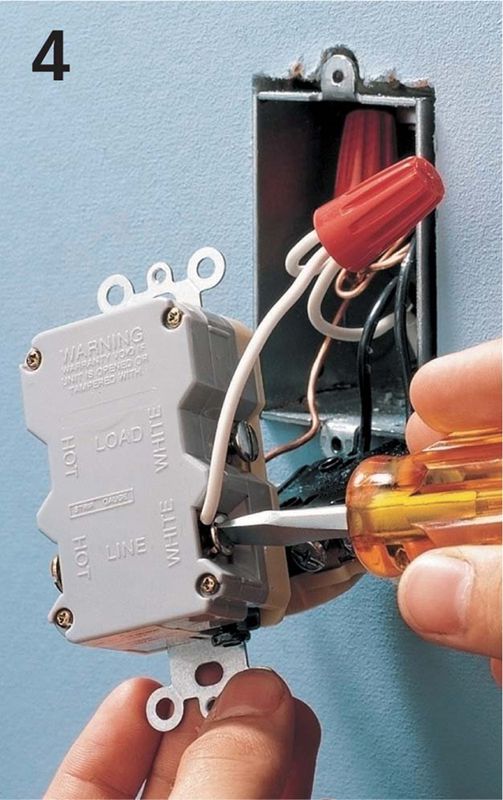
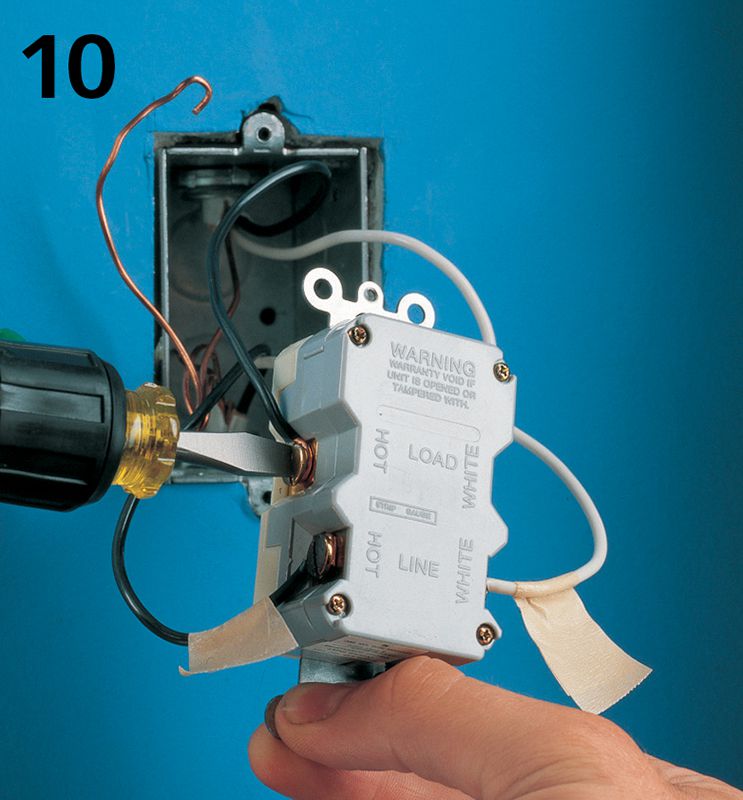
A GFCI wired for single-location protection (shown from the back) has hot and neutral wires connected only to the screw terminals marked LINE. A GFCI connected for single-location protection may be wired as either an end-of-run or middle-of-run configuration.
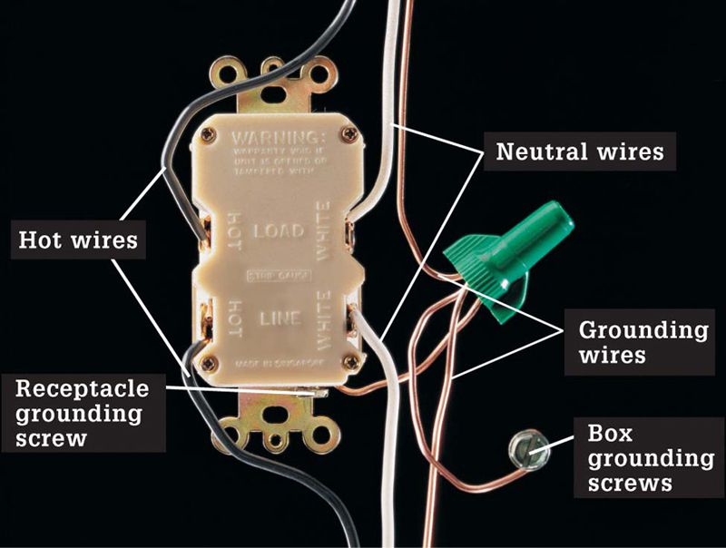
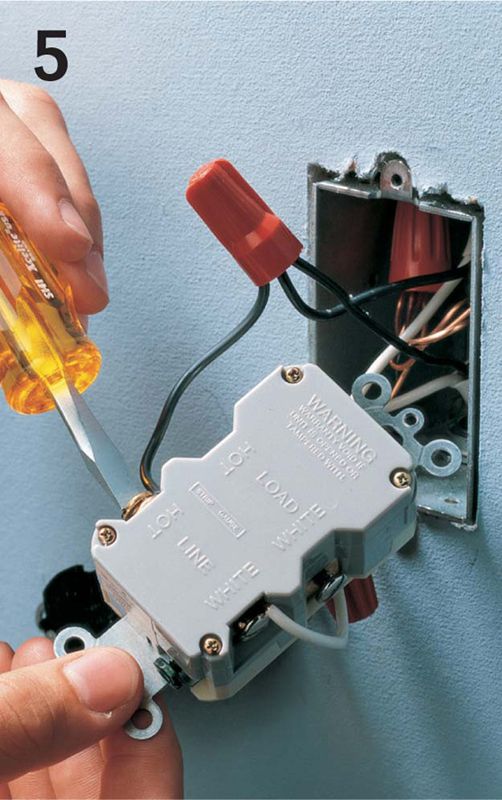
A GFCI wired for multiple-location protection (shown from the back) has one set of hot and neutral wires connected to the LINE pair of screw terminals, and the other set connected to the LOAD pair of screw terminals. A GFCI receptacle connected for multiple-location protection may be wired only as a middle-of-run configuration.
 HOW TO INSTALL A GFCI FOR SINGLE-LOCATION PROTECTION
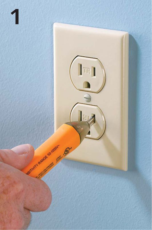
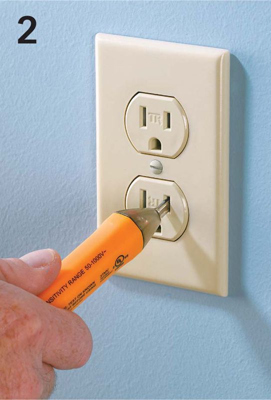
Shut off power to the receptacle at the main service panel. Test for power with a neon circuit tester. Be sure to check both halves of the receptacle.
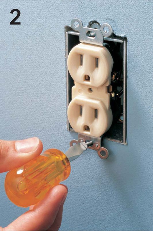
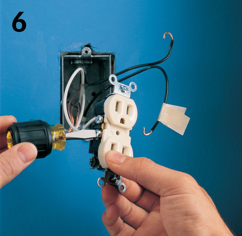
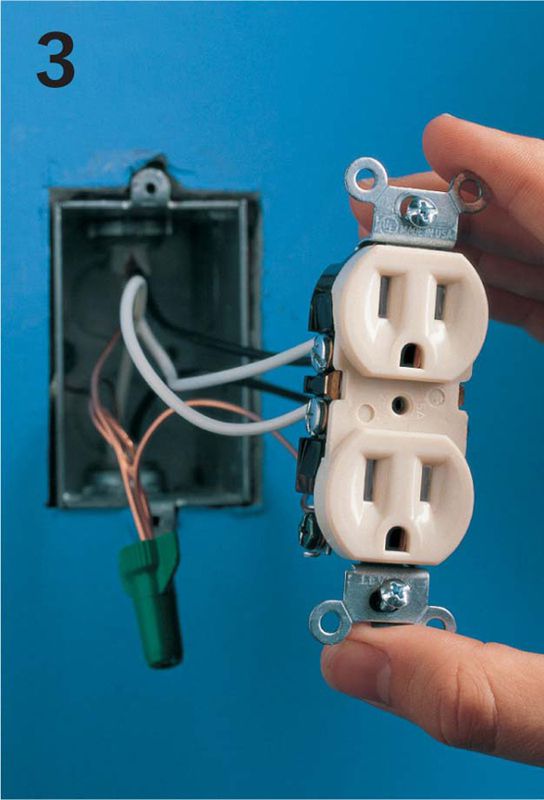
Remove cover plate. Loosen mounting screws, and gently pull receptacle from the box. Do not touch wires. Confirm power is off with a circuit tester.
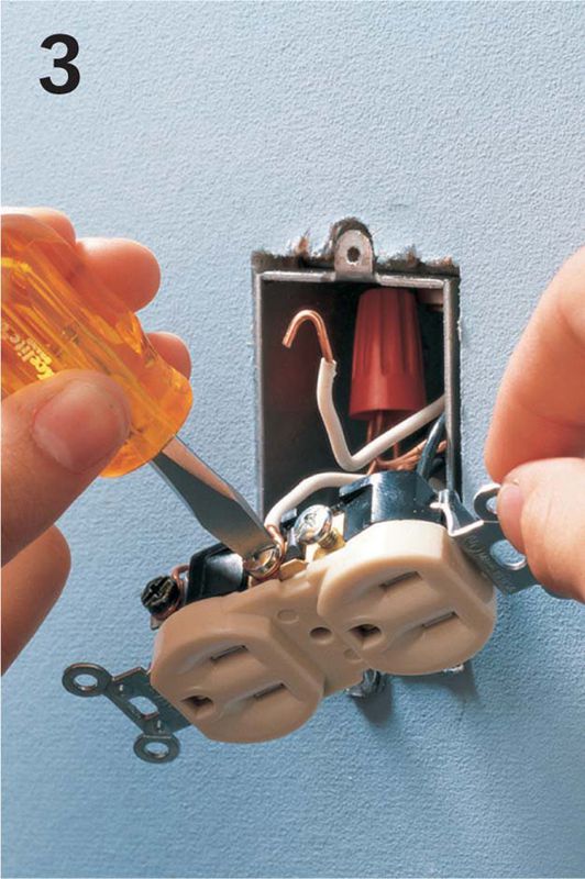
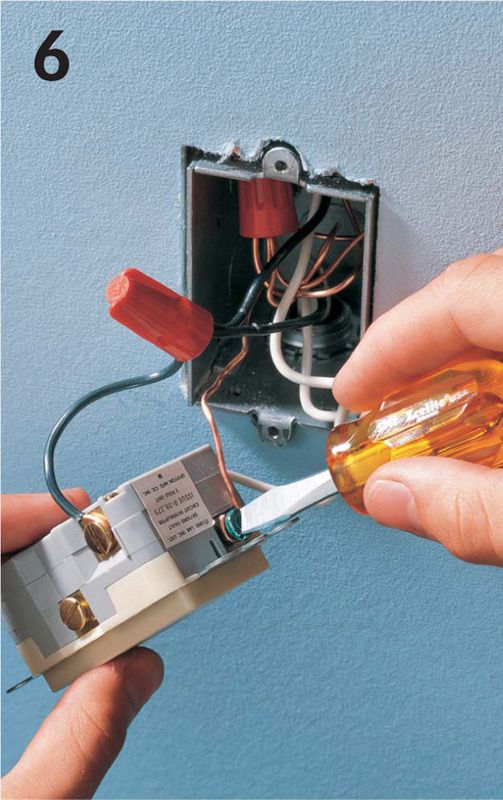
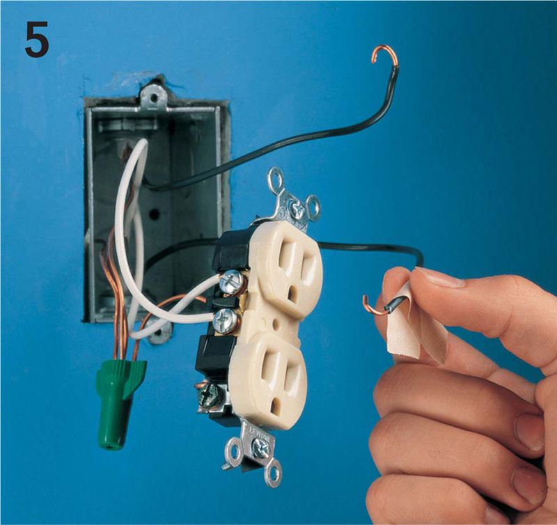
Disconnect all white neutral wires from the silver screw terminals of the old receptacle.
Pigtail all the white neutral wires together, and connect the pigtail to the terminal marked WHITE LINE on the GFCI (see photo on page 216).
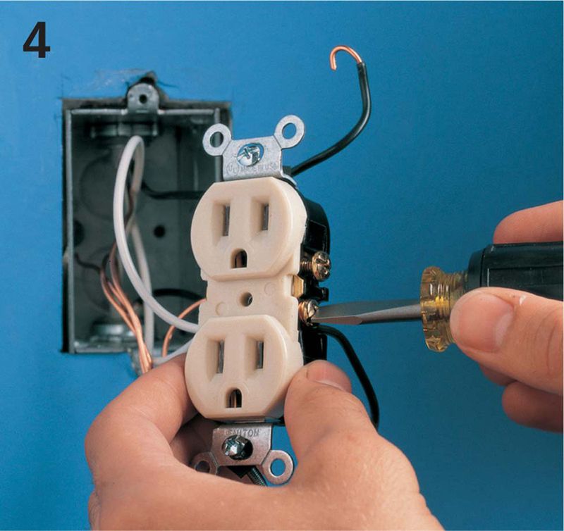
Disconnect all black hot wires from the brass screw terminals of the old receptacle. Pigtail these wires together, and connect them to the terminal marked HOT LINE on the GFCI.
If a grounding wire is available, connect it to the green grounding screw terminal of the GFCI. Mount the GFCI in the receptacle box, and reattach the cover plate. Restore power, and test the GFCI according to the manufacturer’s instructions.
HOW TO INSTALL A GFCI FOR MULTIPLE-LOCATION PROTECTION
Use a map of your house circuits to determine a location for your GFCI. Indicate all receptacles that will be protected by the GFCI installation.
Turn off power to the correct circuit at the main service panel. Test all the receptacles in the circuit with a neon circuit tester to make sure the power is off. Always check both halves of each duplex receptacle.
Remove the cover plate from the receptacle that will be replaced with the GFCI. Loosen the mounting screws and gently pull the receptacle from its box. Take care not to touch any bare wires. Confirm the power is off with a neon circuit tester.
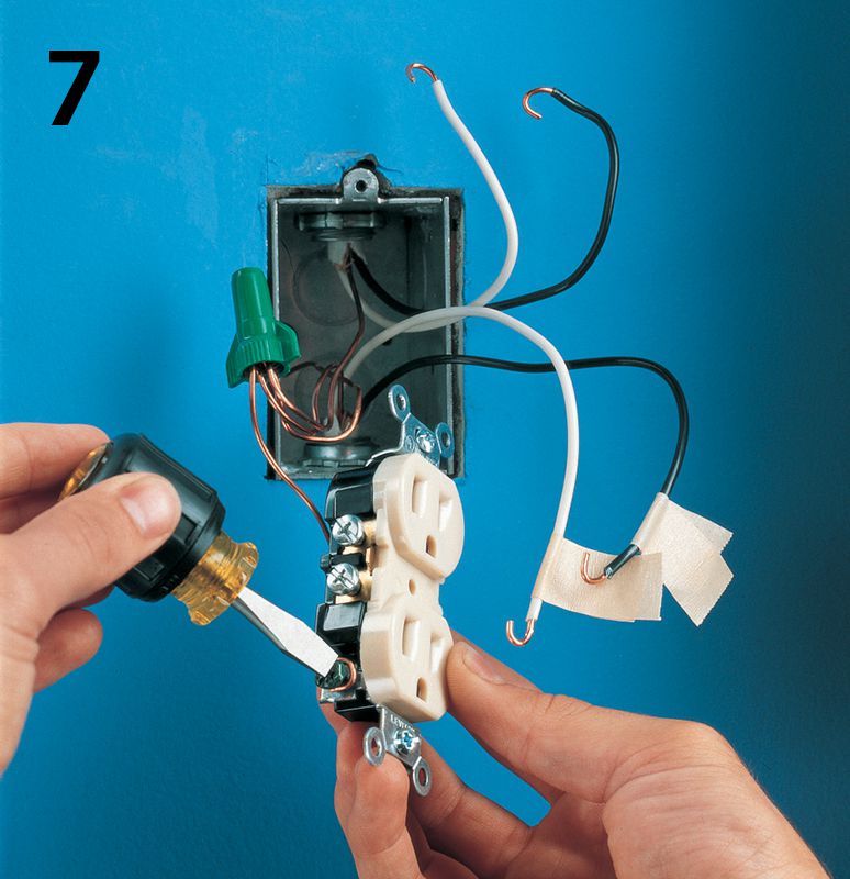
Disconnect all black hot wires. Carefully separate the hot wires and position them so that the bare ends do not touch anything. Restore power to the circuit at the main service panel. Determine which black wire is the feed wire by testing for hot wires. The feed wire brings power to the receptacle from the service panel. Use caution: This is a live wire test, during which the power is turned on temporarily.
When you have found the hot feed wire, turn off power at the main service panel. Identify the feed wire by marking it with masking tape.
Disconnect the white neutral wires from the old receptacle. Identify the white feed wire and label it with masking tape. The white feed wire will be the one that shares the same cable as the black feed wire.
Disconnect the grounding wire from the grounding screw terminal of the old receptacle. Remove the old receptacle. Connect the grounding wire to the grounding screw terminal of the GFCI.
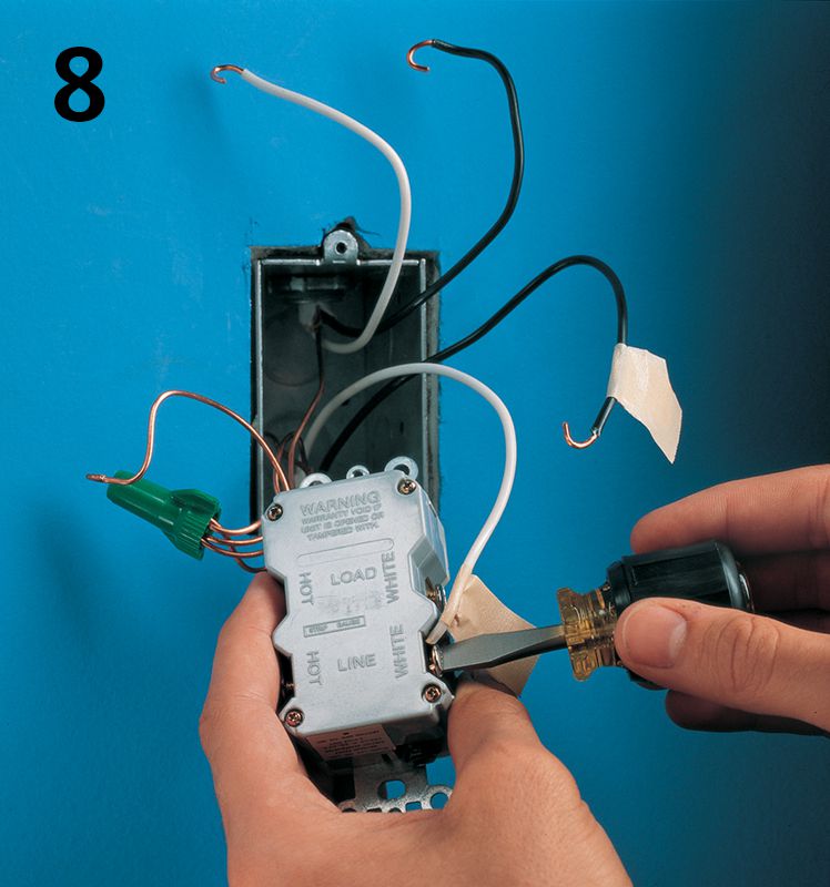
Connect the white feed wire to the terminal marked WHITE LINE on the GFCI. Connect the black feed wire to the terminal marked HOT LINE on the GFCI.
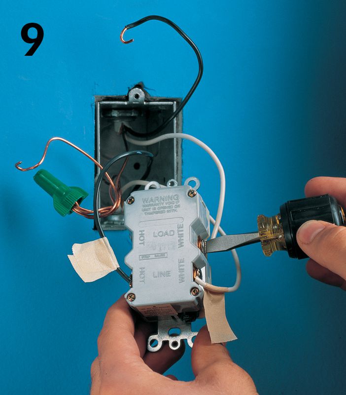
Connect the other white neutral wire to the terminal marked WHITE LOAD on the GFCI.
Connect the other black hot wire to the terminal marked HOT LOAD on the GFCI.
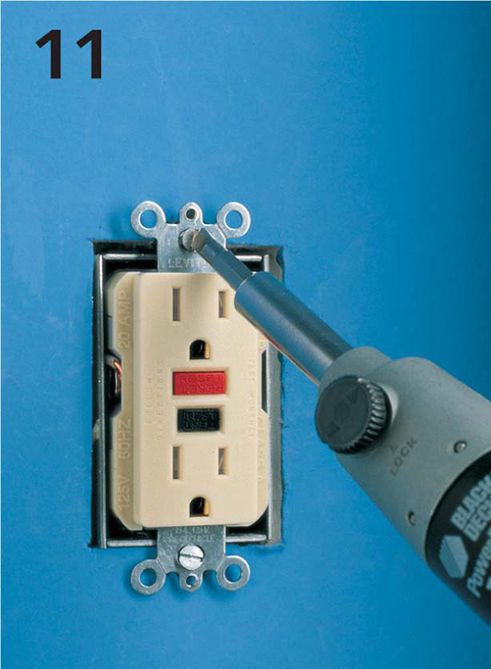
Carefully tuck all wires into the receptacle box. Mount the GFCI in the box and attach the cover plate. Turn on power to the circuit at the main service panel. Test the GFCI according to the manufacturer’s instructions.