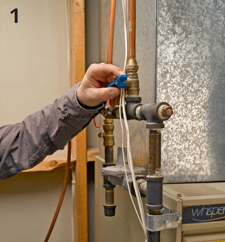
Shut off the gas supply at the stopcock installed in the gas line closest to the water heater. The handle of the stopcock should be perpendicular to the gas supply pipe. Also shut off the water supply.
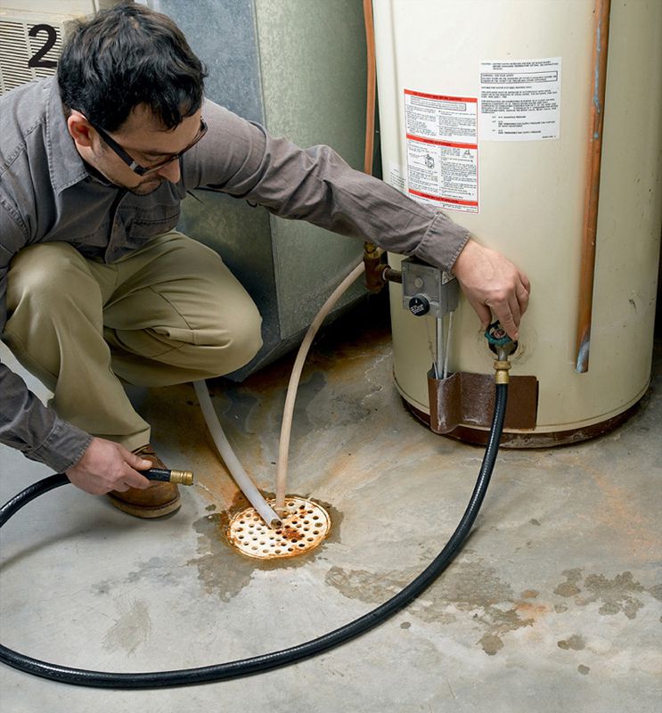
Drain the water from the old heater by hooking a garden hose up to the sillcock drain and running it to a floor drain. If you don’t have a floor drain, drain the water into buckets. For your personal safety, wait until the water heater has been shut off for a couple of hours before draining it.
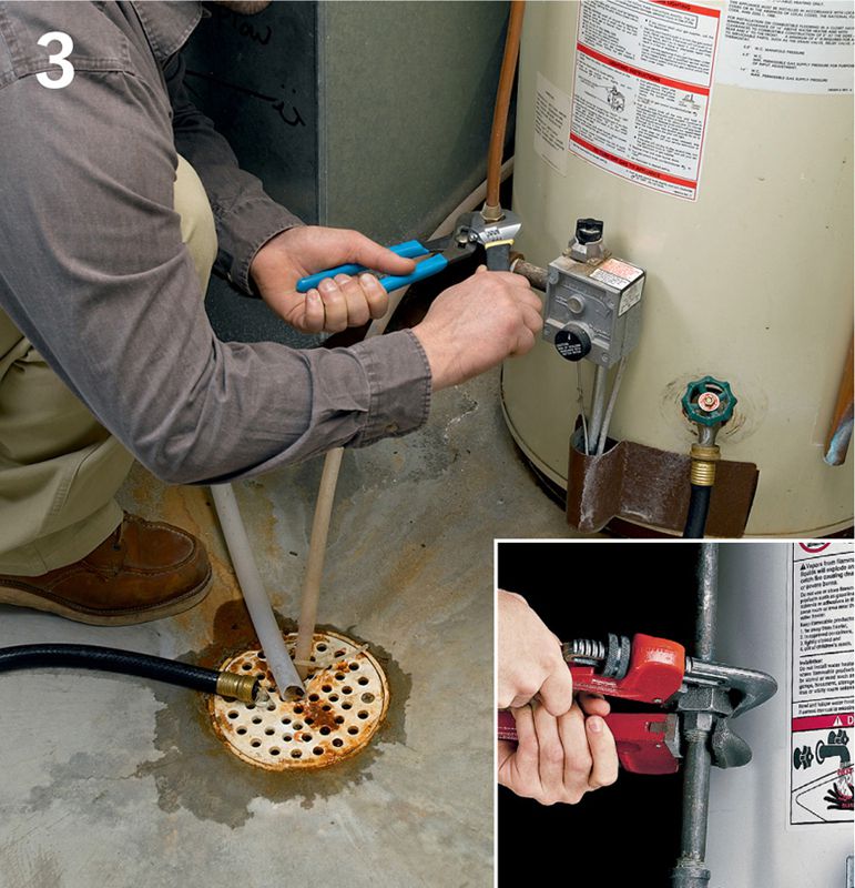
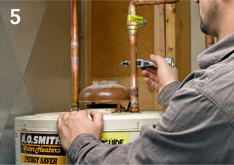
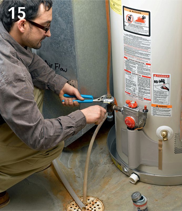
Disconnect the gas supply from the water heater. To do so, loosen the flare fitting with two wrenches or pliers in a soft copper supply line or loosen the union fitting with two pipe wrenches for black pipe supply lines (inset photo).
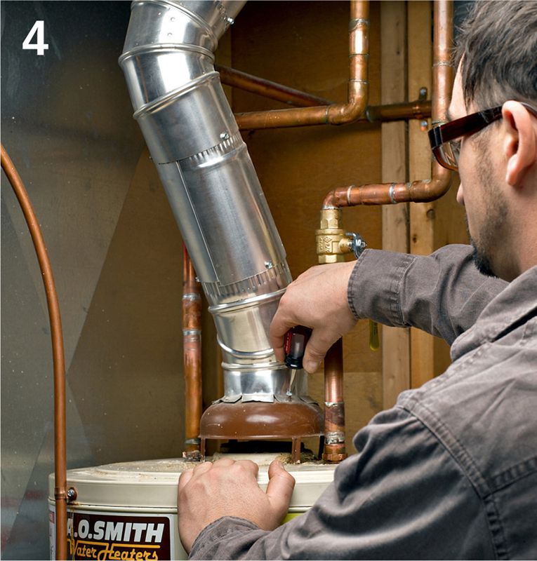
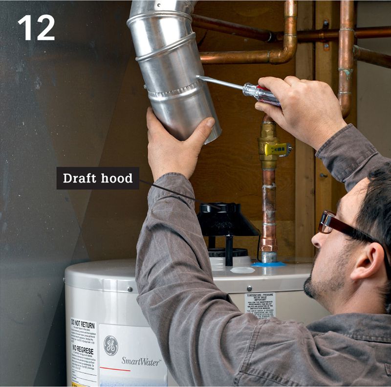
Disconnect the vent pipe from the draft hood by withdrawing the sheet metal screws connecting the parts. Also remove vent pipes up to and including the elbow so you may inspect them for corrosion buildup and replace if needed.
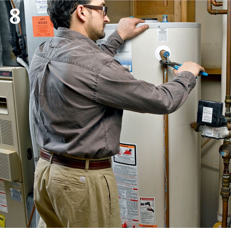
Cut the water supply lines. Prior to cutting, shut off the cold water supply either at the stop valve near the heater or at the water meter. Inspect the shutoff valve. If it is not a ball-type valve in new condition, replace it with a ball valve.
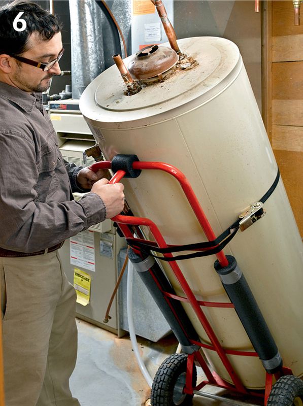
Remove the old water heater and dispose of it properly. Most trash collection companies will haul it away for $20 or $30. Don’t simply leave it out at the curb unless you know that is allowed by your municipal waste collection department. A two-wheel truck or appliance dolly is a big help here. Water heaters usually weigh around 150 pounds.
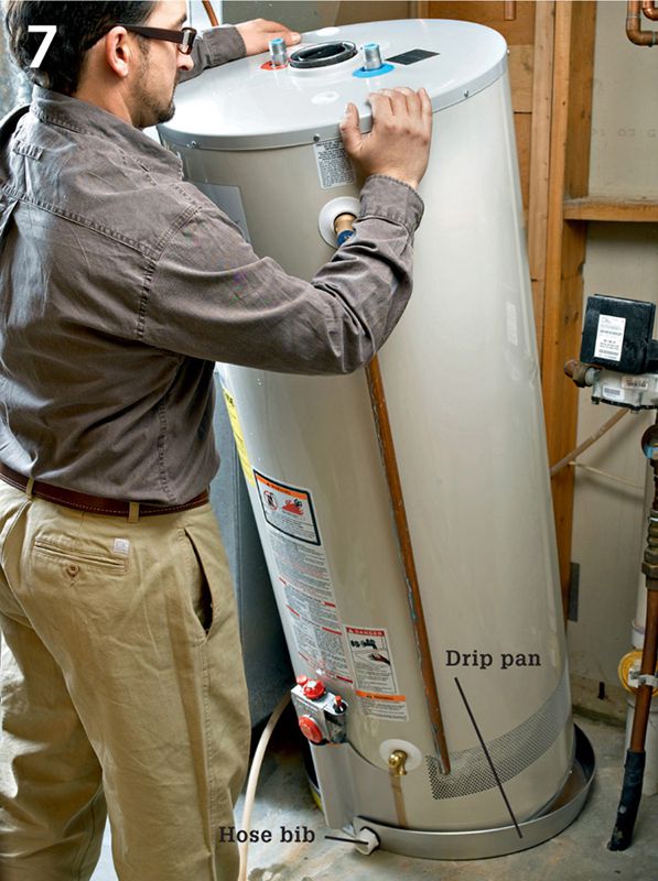
Position the new unit in the installation area. If you have flooring you wish to protect from leaks, set the unit on a drip pan (available where water heater accessories are sold). The shallow pans feature a hose bib so you can run a drain line from the pan to a floor drain. If the water heater is not level, level it by shimming under the bottom with a metal or composite shim. Note that you’ll need to shift the unit around a bit to have clearance for installing the water supply connectors (step 10).
Install a Relief Valve 
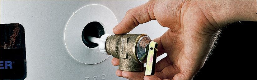
Prepare the new water heater for installation. Before you put the water heater in place, add a T & P (temperature and pressure) relief valve at the valve opening. Make sure to read the manufacturer’s instructions and purchase the recommended valve type. Lubricate the threads and tighten the valve into the valve opening with a pipe wrench. Note: The water heater shown in this sequence came with a T & P relief valve that’s preinstalled.
Attach a discharge tube to the T & P relief valve. You may use either copper pipe or CPVC drain pipe. Cut the tube so the free end is 6" above the floor (some locales may allow 3" above the floor). If you have floorcoverings you wish to protect, add a 90° elbow and a copper drain tube that leads from the discharge tube to a floor drain.
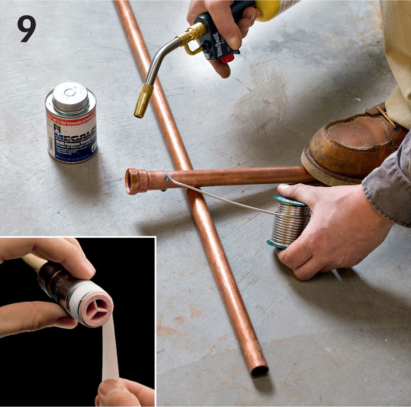
Fabricate water connectors from lengths of copper tubing, threaded copper adaptors, and plastic-lined galvanized threaded nipples. Plastic-lined nipples (inset photo) reduce the corrosion that can occur when you join two dissimilar metals. Size the connector assemblies so they will end up just short of the cut copper supply tubing when the connectors are inserted into the water heater ports.
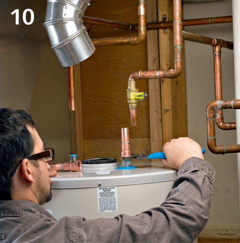
Install the connectors in the cold water inlet port (make sure you use the blue-coded lined nipple) and the hot outlet port (red-coded nipple) on top of the water heater. Lubricate the nipple threads and tighten with channel-type pliers. Slip a copper tubing repair coupling over each connector and reposition the unit so the supply pipes and connector tops align.
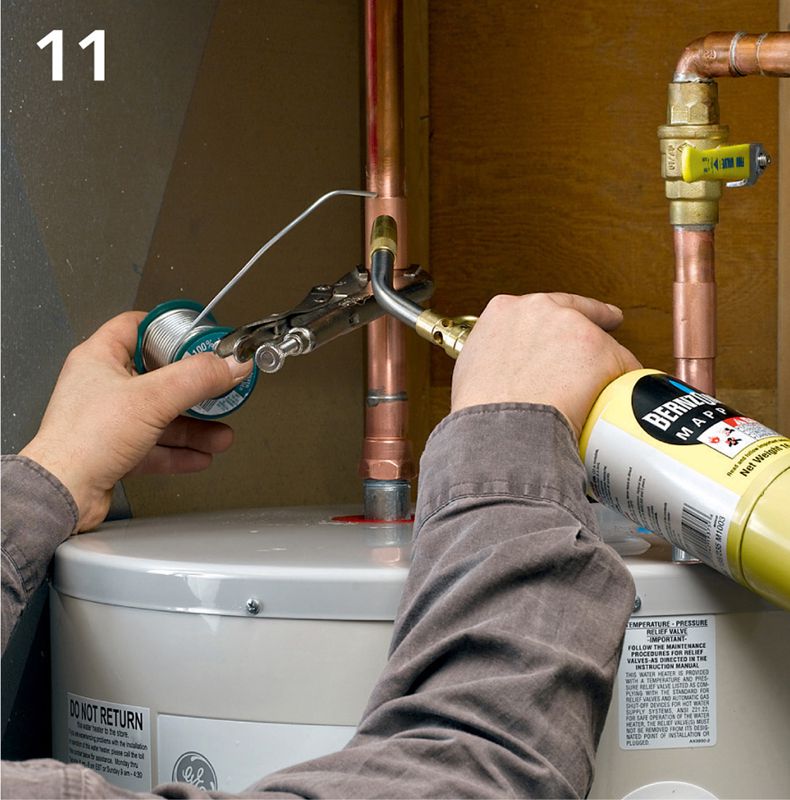
Join the connectors to the supply tubes with slip-fitting copper repair couplings. Be sure to clean and prime the parts first.
Reassemble the vent with a new elbow fitting (if your old one needed replacement, see step 4, page 540). Cut the duct that drops down from the elbow so it will fit neatly over the top flange of the draft hood.
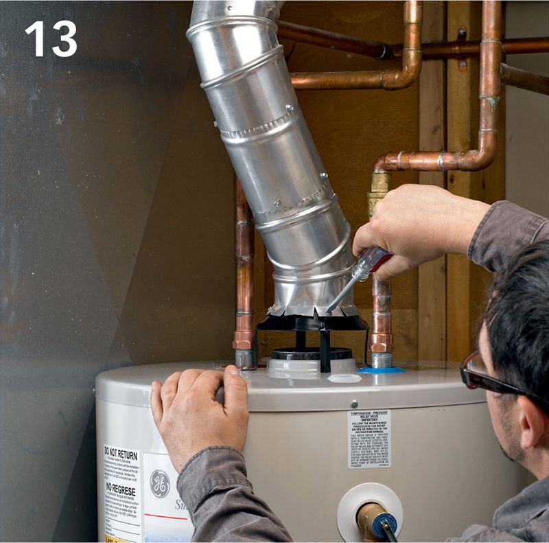
Follow the manufacturer’s instructions for configuring the vent; this varies from model to model. Attach the vertical leg of the vent line to the draft hood with 3/8" sheet metal screws. Drive at least three screws into each joint.
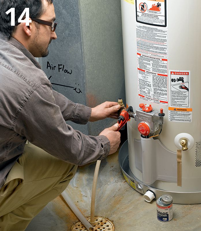
Install the parts for the black pipe gas connector assembly (see photo page 540). Use pipe dope to lubricate all joints. Attach a T-fitting to one end of a 3" nipple first and attach the other end of the nipple into the female-threaded regulator port. Attach a cap to another 6" nipple and then thread the other end into the bottom opening of the T-fitting to form a drip leg. Install a third nipple in the top opening of the T-fitting.
Connect the gas supply line to the open end of the gas connector. Use a union fitting for black gas pipe connections and a flare fitting for copper supply connections. See page 540 for more information on making these connections.
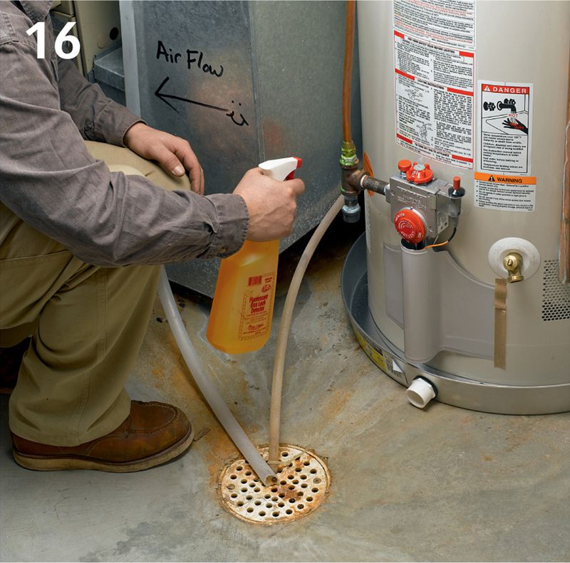
Test the connections. Turn on the gas supply and test the gas connections with testing solution. Before turning on the water supply, make sure the tank drain valve is closed. Allow the tank to fill with water and then turn on a hot water faucet until water comes out (the water won’t be hot yet, of course). Visually check all plumbing joints for leaks.
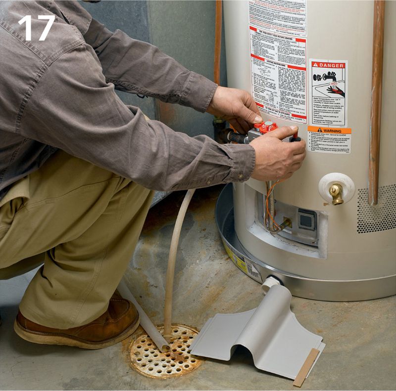
Light the pilot. This is usually a multistep process that varies among manufacturers, but all new water heaters will have pilot-lighting instructions printed on a label near the water heater controls. Adjust the water temperature setting.
Tip: Hooking Up Electric Water Heaters
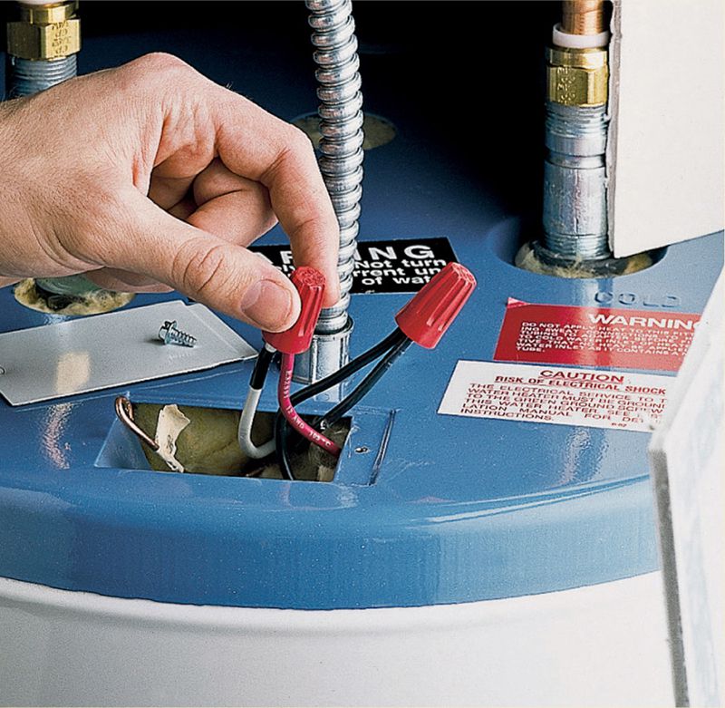
The fuel supply connection is the only part of installing an electric water heater that differs from installing a gas heater, except that electric heaters do not require a vent. The feeder wires (240 volts) are twisted together with mating wires in the access panel located at the top of the unit.
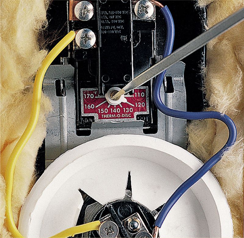
Temperature adjustments on electric water heaters are made by tightening or loosening a thermostat adjustment screw located near the heating element. Always shut off power to the unit before making adjustment. In this photo you can see how close the live terminals for the heating element are to the thermostat.
Gas water heater parts include:
(A) Flue
(B) Hot water outlet
(C) Tank
(D) Anode rod
(E) Gas burner
(F) Cold water inlet pipe
(G) Pressure-relief valve
(H) Dip tube
(I) Thermostat
(J) Thermocouple
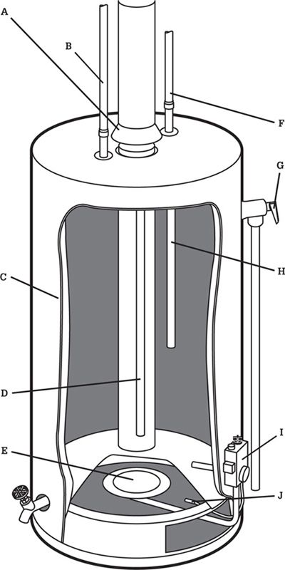
Gas water heaters operate on either propane or natural gas and are generally very economical to run. They do cost a bit more than electric heaters up front. The following installation features a gas water heater. Check with your local building department to find out if homeowners are allowed to install gas appliances in your municipality.
ELECTRIC WATER HEATER
Electric water heater parts can include:
(A) Cold water inlet pipe
(B) Cold water inlet valve
(C) Insulation
(D) Draincock
(E) Hot water outlet pipe
(F) Pressure-relief valve
(G) Power cable
(H) High temperature thermostat
(I) Upper heating element
(J) Bracket
(K) Lower heating thermostat
(L) Lower heating element
(M) Gasket
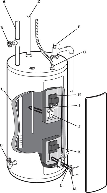
Electric water heaters require 240-volt service, which might overload your service panel if you are replacing a gas heater with an electric model. Their primary advantage is that they are cheaper to purchase (but not to operate) and they do not require that you make gas connections.