Predict the behavior of a capacitor when charging and discharging
Describe the impact of a dielectric on capacitance, voltage, and charge
Recognize the physical properties that impact capacitance of a capacitor
Contrast the effects of a capacitor on a circuit in series as compared to a circuit in parallel:
Aside from batteries and resistors, the other major circuit element tested on the
MCAT is the capacitor. Capacitors are characterized by their ability to hold charge at a particular voltage. There
are excellent real-world examples of capacitors. Perhaps the most important capacitor
you’ll encounter in the clinics is the defibrillator. While a defibrillator is charging,
a high-pitched electronic tone sounds as electrons build up on the capacitor. When
the defibrillator is fully charged, that charge can be released in one surge of power
(after the operator yells Clear!). The clouds and the ground during a lightning storm also act as a capacitor, with
the charge building up between them eventually discharging as a bolt of lightning. The MCAT focuses on a particular type of capacitor called
a parallel plate capacitor, and all of our discussion will center on capacitors of
this type.
Properties of Capacitors
When two electrically neutral metal plates are connected to a voltage source, positive
charge builds up on the plate connected to the positive (higher potential) terminal,
and negative charge builds up on the plate connected to the negative (lower potential)
terminal. The two-plate system is a capacitor because it can store a particular amount
of charge at a particular voltage. The capacitance of a capacitor is defined as the ratio of the magnitude of the charge stored on one
plate to the potential difference (voltage) across the capacitor. Therefore, if a
voltage V is applied across the plates of a capacitor and a charge Q collects on it (with +Q on the positive plate and –Q on the negative plate), then the capacitance is given by
The SI unit for capacitance is the farad
. Because one coulomb is such a large quantity of charge, one farad is a very large
capacitance. Capacitances are usually given in microfarads (1 μF = 1 × 10⁻⁶ F) or picofarads (1 pF = 1 × 10–12 F). Be careful not to confuse the farad with the Faraday constant from electrochemistry,
F, which is the amount of charge in one mole of electrons
.
The capacitance of a parallel plate capacitor is dependent upon the geometry of the
two conduction surfaces. For the simple case of the parallel plate capacitor, the
capacitance is given by
where ε0 is the permittivity of free space
A is the area of overlap of the two plates, and d is the separation of the two plates. The separation of charges sets up a uniform electric field between the plates with parallel field vectors, the magnitude of which can be calculated
as
Key Concept
If you look back to the equations discussed in Chapter 5 of MCAT Physics and Math Review, you can see that the equation for E here can be derived from the other fundamental electrostatics equations. If
and
, then V = E × r.r in this setup is the distance between the plates, d, so we can rewrite this as V = Ed.
The direction of the electric field at any point between the plates is from the positive
plate toward the negative plate. If we imagine placing a positively charged particle
between the oppositely charged plates, we would expect the particle to accelerate
in that same direction. This should not be surprising, as electric field lines always
point in the direction that indicates the direction of a force exerted on a positive charge.
Regardless of the particular geometry of a capacitor (parallel plate or otherwise),
the function of a capacitor is to store an amount of energy in the form of charge
separation at a particular voltage. This is akin to the function of a dam, the purpose
of which is to store gravitational potential energy by holding back a mass of water
at a given height. The potential energy stored in a capacitor is
Dielectric Materials
The term dielectric material is just another way of saying insulation. When a dielectric material, such as air,
glass, plastic, ceramic, or certain metal oxides, is introduced between the plates
of a capacitor, it increases the capacitance by a factor called the dielectricconstant (κ). The dielectric constant of a material is a measure of its insulating ability, and
a vacuum has a dielectric constant of 1, by definition. For reference, the dielectric
constant of air is just slightly above 1, glass is 4.7, and rubber is 7. These numbers
need not be memorized; any relevant dielectric constants will be given on Test Day.
The capacitance due to a dielectric material is
where C′ is the new capacitance with the dielectric present and C is the original capacitance.
Key Concept
A dielectric material can never decrease the capacitance; thus, κ can never be less than 1.
Dielectrics in Isolated Capacitors
When a dielectric material is placed in an isolated, charged capacitor—that is, a
charged capacitor disconnected from any circuit—the voltage across the capacitor decreases.
This is the result of the dielectric material shielding the opposite charges from
each other. By lowering the voltage across a charged capacitor, the dielectric has
increased the capacitance of the capacitor by a factor of the dielectric constant.
Thus, when a dielectric material is introduced into an isolated capacitor, the increase
in capacitance arises from a decrease in voltage.
Dielectrics in Circuit Capacitors
When a dielectric material is placed in a charged capacitor within a circuit—that
is, still connected to a voltage source—the charge on the capacitor increases. The
voltage must remain constant because it must be equal to that of the voltage source.
By increasing the amount of charge stored on the capacitor, the dielectric has increased
the capacitance of the capacitor by a factor of the dielectric constant. Thus, when
a dielectric material is introduced into a circuit capacitor, the increase in capacitance
arises from an increase in stored charge.
The stored energy in a capacitor is only useful if it is allowed to discharge. The
charge can be released from the plates either by discharging across the plates or
through some conductive material with which the plates are in contact. For example,
capacitors can discharge into wires, causing a current to pass through the wires in
much the same way that batteries cause current to move through a circuit. The paddles
of the defibrillator machine, once charged, are placed on either side of a patient’s
heart that has gone into a life-threatening arrhythmia (such as ventricular fibrillation). The reason the doctor yells Clear! before discharging the paddles is because the current needs to travel through the
patient’s heart—not through any other people who might be touching the patient and
creating a parallel pathway. On a much larger scale, lightning occurs when a very,
very large amount of charge exceeds the capacitance of the Earth’s surface and the
underside of the cloud (the two serving, approximately, as a parallel plate capacitor).
The large rapid discharge across the plates of a capacitor is termed a failure of
the capacitor, while creating a current through the attached wires is the normal function
of a capacitor.
Capacitors in Series and Parallel
Just like resistors, capacitors can be arranged within a circuit either in parallel
or in series. They can also be arranged with resistors, although this is beyond the
scope of the MCAT in most cases.
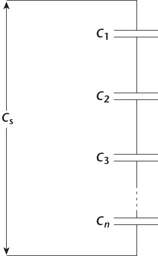
Capacitors in Series
When capacitors are connected in series, the total capacitance decreases in similar
fashion to the decreases in resistance seen in parallel resistors, as shown in Figure
6.3.
Figure6.3.Capacitors in SeriesCs decreases as more capacitors are added.
This is because the capacitors must share the voltage drop in the loop and therefore
cannot store as much charge. Functionally, a group of capacitors in series acts like
one equivalent capacitor with a much larger distance between its plates (in fact,
with a distance equal to those of each of the series capacitors added together). This
increase in distance, as seen earlier, means a smaller capacitance.
Rather than memorizing the following equations independently, understand the conceptual
basis for the mathematics of resistors in series and in parallel, and then simply
reverse that mathematical approach for capacitors. The equation for calculating the
equivalent capacitance for capacitors in series is
which shows that Cs decreases as more capacitors are added. Note that for capacitors in series, the total
voltage is the sum of the individual voltages, just like resistors in series.
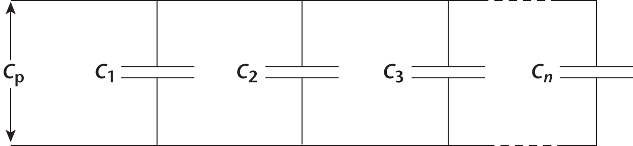
Capacitors in Parallel
Capacitors wired in parallel, shown in Figure 6.4, produce a resultant capacitance
that is equal to the sum of the individual capacitances.
Figure6.4.Capacitors in ParallelCp increases as more capacitors are added.
Therefore, Cp increases as more capacitors are added:
Just as we saw with resistors in parallel, the voltage across each parallel capacitor
is the same and is equal to the voltage across the source.

 . Because one coulomb is such a large quantity of charge, one farad is a very large
capacitance. Capacitances are usually given in microfarads
. Because one coulomb is such a large quantity of charge, one farad is a very large
capacitance. Capacitances are usually given in microfarads  .
.
 A is the area of overlap of the two plates, and d is the separation of the two plates. The separation of charges sets up a uniform electric field between the plates with parallel field vectors, the magnitude of which can be calculated
as
A is the area of overlap of the two plates, and d is the separation of the two plates. The separation of charges sets up a uniform electric field between the plates with parallel field vectors, the magnitude of which can be calculated
as
 and
and
 , then