After Chapter 8.2, you will be able to:
When light travels through a homogeneous medium, it travels in a straight line. This is known as rectilinear propagation. The behavior of light at the boundary of a medium or interface between two media is described by the theory of geometrical optics. Geometrical optics explains reflection and refraction, as well as the applications of mirrors and lenses.
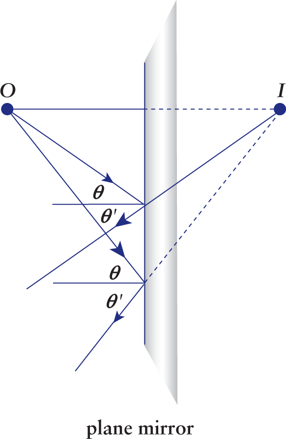
Reflection is the rebounding of incident light waves at the boundary of a medium. Light waves that are reflected are not absorbed into the second medium; rather, they bounce off of the boundary and travel back through the first medium. Figure 8.3 illustrates reflection on a plane mirror.
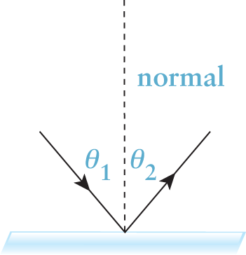
The law of reflection is
where θ1 is the incident angle and θ2 is the reflected angle, both measured from the normal. The normal is a line drawn perpendicular to the boundary of a medium; all angles in optics are measured from the normal, not the surface of the medium.
In general, images created by a mirror can be either real or virtual. An image is said to be real if the light actually converges at the position of the image. An image is virtual if the light only appears to be coming from the position of the image but does not actually converge there. One of the distinguishing features of real images is the ability of the image to be projected onto a screen.
Parallel incident light rays remain parallel after reflection from a plane mirror; that is, plane mirrors—being flat reflective surfaces—cause neither convergence nor divergence of reflected light rays. Because the light does not converge at all, plane mirrors always create virtual images. In a plane mirror, the image appears to be the same distance behind the mirror as the object is in front of it, as shown in Figure 8.4. In other words, plane mirrors create the appearance of light rays originating behind the mirrored surface. Because the reflected light remains in front of the mirror but the image appears behind the mirror, the image is virtual. Plane mirrors include most of the common mirrors found in our homes. To assist in our discussion of spherical mirrors, plane mirrors can be conceptualized as spherical mirrors with an infinite radius of curvature.
Spherical mirrors come in two varieties: concave and convex. The word spherical implies that the mirror can be considered a spherical cap or dome taken from a much larger spherically shaped mirror. Spherical mirrors have an associated center of curvature (C) and a radius of curvature (r). The center of curvature is a point on the optical axis located at a distance equal to the radius of curvature from the vertex of the mirror; in other words, the center of curvature would be the center of the spherically shaped mirror if it were a complete sphere.
The passenger-side mirrors in cars are an example of convex mirrors (everything appears smaller and farther away); the small circular mirrors used for applying makeup are an example of concave mirrors (everything appears bigger and closer).
If we were to look from the inside of a sphere to its surface, we would see a concave surface. On the other hand, if we were to look from outside the sphere, we would see a convex surface. For a concave surface, the center of curvature and the radius of curvature are located in front of the mirror. For a convex surface, the center of curvature and the radius of curvature are behind the mirror. Concave mirrors are called converging mirrors and convex mirrors are called diverging mirrors because they cause parallel incident light rays to converge and diverge after they reflect, respectively.
Concave is like looking into a cave.
Concave mirrors are converging mirrors. Convex mirrors are diverging mirrors. The reverse is true for lenses.
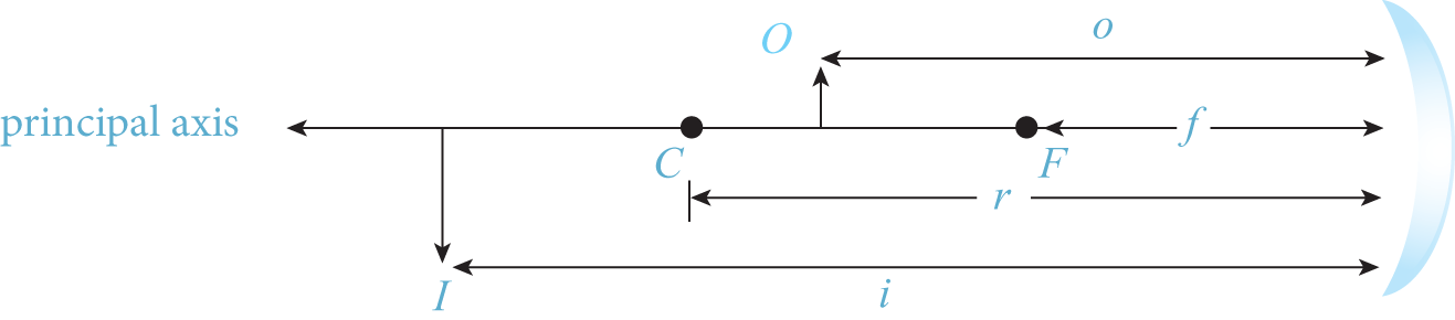
There are several important lengths associated with mirrors, as shown in Figure 8.5.
The focal length (f) is the distance between the focal point (F) and the mirror. Note that for all spherical mirrors,
 where the radius of curvature (r) is the distance between C and the mirror. The distance between the object and the mirror is o; the distance between the image and the mirror is i.
There is a simple relationship between these four distances:
While it is not important which units of distance are used in this equation, it is important that all values used have the same units as each other.
On the MCAT, you will most often use this equation to calculate the image distance for all types of mirrors and lenses. If the image has a positive distance (i > 0), it is a real image, which implies that the image is in front of the mirror. If the
image has a negative distance (i < 0), it is virtual and thus located behind the mirror. Plane mirrors can be thought of
as spherical mirrors with infinitely large focal distances. As such, for a plane mirror,
r = f = ∞, and the equation becomes
 or i = –o. This can be interpreted as saying the virtual image is at a distance behind the
mirror equal to the distance the object is in front of the mirror.
or i = –o. This can be interpreted as saying the virtual image is at a distance behind the
mirror equal to the distance the object is in front of the mirror.
The magnification (m) is a dimensionless value that is the ratio of the image distance to the object distance:
By extension, the magnification also gives the ratio of the size of the image to the size of the object. Following the sign convention given later in Table 8.1, the orientation of the image (upright or inverted) can be determined: a negative magnification signifies an inverted image, while a positive value signifies an upright image. If |m| < 1, the image is smaller than the object (reduced); if |m| > 1, the image is larger than the object (enlarged); and if |m| = 1, the image is the same size as the object.
Figure 8.6 shows ray diagrams for a concave spherical mirror with the object at three different points. A ray diagram is useful for getting an approximation of where an image is. On Test Day, ray diagrams can be helpful for a quick determination of the type of image that will be produced by an object some distance from the mirror (real vs. virtual, inverted vs. upright, and magnified vs. reduced). Ray diagrams should be used with caution, however: under the pressure of Test Day, it can be easy to draw them incorrectly. Therefore, it is important to practice drawing ray diagrams to avoid careless errors on Test Day, and it is also important to be familiar with how to solve optics questions mathematically.
When drawing a ray diagram, there are three important rays to draw. For a concave mirror, a ray that strikes the mirror parallel to the axis (the normal passing through the center of the mirror) is reflected back through the focal point (green lines in Figure 8.6 and 8.7). A ray that passes through the focal point before reaching the mirror is reflected back parallel to the axis (red lines). A ray that strikes the mirror at the point of intersection with the axis is reflected back with the same angle measured from the normal (blue lines). In Figure 8.6a, the object is placed beyond F, and the image produced is real, inverted and magnified. In Figure 8.6b, the object is placed at F, and no image is formed because the reflected light rays are parallel to each other. In terms of the mirror equation, we say that the image distance i = ∞ here. For the scenario in Figure 8.6c, the object is placed between F and the mirror, and the image produced is virtual, upright, and magnified.
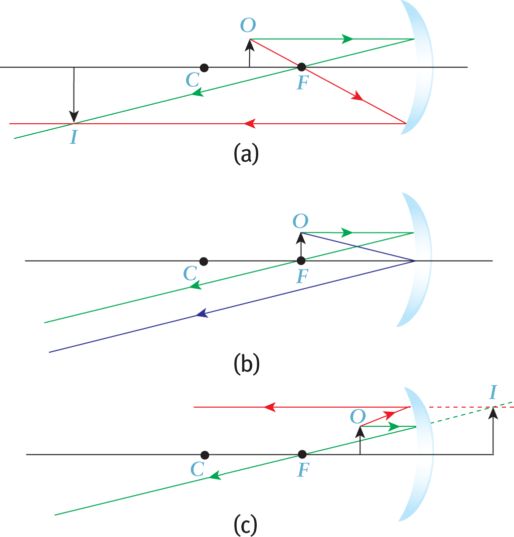
Any time an object is at the focal point of a converging mirror, the reflected rays will be parallel, and thus, the image will be at infinity.
A single diverging mirror forms only a virtual, upright, and reduced image, regardless of the position of the object. The farther away the object, the smaller the image will be. To quickly remember these rules, recall the convenience store security mirrors mentioned at the beginning of the chapter. The ray diagram of a diverging mirror is shown in Figure 8.7.
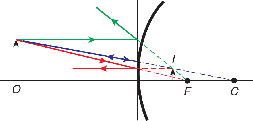
To find where the image is (for a mirror), draw the following rays and find a point where any two intersect. This point of intersection marks the tip of the image. If the rays you draw do not appear to intersect, extend them to the other side of the mirror, creating a virtual image.
Table 8.1 provides the sign convention for single mirrors. Note that on the MCAT, for almost all problems involving mirrors, the object will be placed in front of the mirror. Thus, the object distance o is almost always positive.
| Symbol | Positive | Negative |
| o | Object is in front of mirror | Object is behind mirror (extremely rare) |
| i | Image is in front of mirror (real) | Image is behind mirror (virtual) |
| r | Mirror is concave (converging) | Mirror is convex (diverging) |
| f | Mirror is concave (converging) | Mirror is convex (diverging) |
| m | Image is upright (erect) | Image is inverted |
The focal length of converging mirrors (and converging lenses) will always be positive. The focal length of diverging mirrors (and diverging lenses) will always be negative.
Image types with a single lens or mirror (assuming o is positive): UV NO IR
Refraction is the bending of light as it passes from one medium to another and changes speed.
The speed of light through any medium is always less than its speed through a vacuum.
Remember that the speed of light in a vacuum, c, is equal to
 The speed of light in air is just slightly lower that this value; on the MCAT, it
is appropriate to use
The speed of light in air is just slightly lower that this value; on the MCAT, it
is appropriate to use
 for the speed of light in air.
When a pencil (or any straight object) is dipped into a glass of water at an angle, it looks impossibly bent where it intersects the surface of the water because the light reflecting off of the portion of the pencil under water is refracted.
When light is in any medium besides a vacuum, its speed is less than c. For a given medium
where c is the speed of light in a vacuum, ν is the speed of light in the medium, and n is a dimensionless quantity called the index of refraction of the medium. The index of refraction of a vacuum is 1, by definition; for all other materials, the index of refraction will be greater than 1. For air, n is essentially equal to 1 because the speed of light in air is extremely close to c. The indices of refraction for a number of common media are shown in Table 8.2. These values are provided only for reference; they need not be memorized.
| Medium | Index of refraction (n) |
| Vacuum | 1 (by definition) |
| Air | 1.0003 |
| Ice | 1.31 |
| Water | 1.33 |
| Acetone | 1.36 |
| Ethanol | 1.36 |
| Cornea (human) | 1.37–1.40 |
| Lens (human) | 1.39–1.41 |
| Glass (various types) | 1.48–1.93 |
| Diamond | 2.42 |
Refracted rays of light obey Snell’s law as they pass from one medium to another:
where n1 and θ1 refer to the medium from which the light is coming and n2 and θ2 refer to the medium into which the light is entering. Note that θ is once again measured with respect to the normal, as shown in Figure 8.8.
From Snell’s law, we can see that when light enters a medium with a higher index of refraction (n2 > n1), it bends toward the normal (sin θ2 < sin θ1; therefore, θ2 < θ1), as shown in Figure 8.9. Conversely, if the light travels into a medium where the index of refraction is smaller (n2 < n1), the light will bend away from the normal (sin θ2 > sin θ1; therefore, θ2 > θ1).
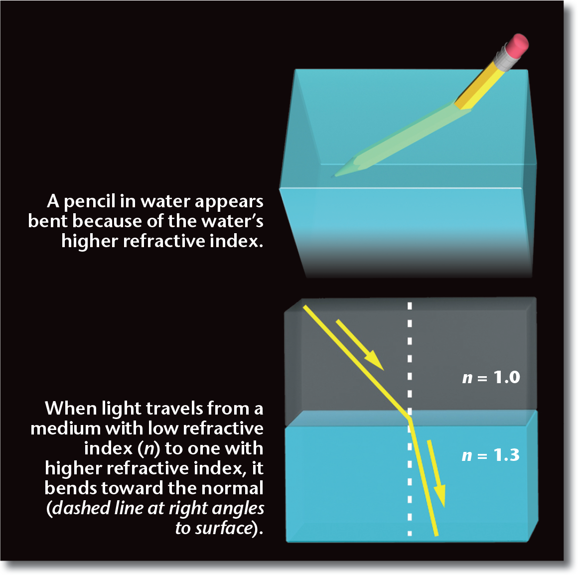
Remember that when light enters a medium with a higher index of refraction, it bends toward the normal. When light enters a medium with a lower index of refraction, it bends away from the normal.
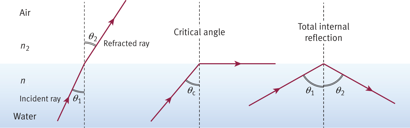
When light travels from a medium with a higher index of refraction (such as water) to a medium with a lower index of refraction (such as air), the refracted angle is larger than the incident angle (θ2 > θ1); that is, the refracted light ray bends away from the normal. As the incident angle is increased, the refracted angle also increases, and eventually, a special incident angle called the critical angle (θc) is reached, for which the refracted angle θ2 equals 90 degrees. At the critical angle, the refracted light ray passes along the interface between the two media. The critical angle can be derived from Snell’s law if θ2 = 90°, such that
Total internal reflection, a phenomenon in which all the light incident on a boundary is reflected back into the original material, results with any angle of incidence greater than the critical angle, θc, as shown in Figure 8.10.
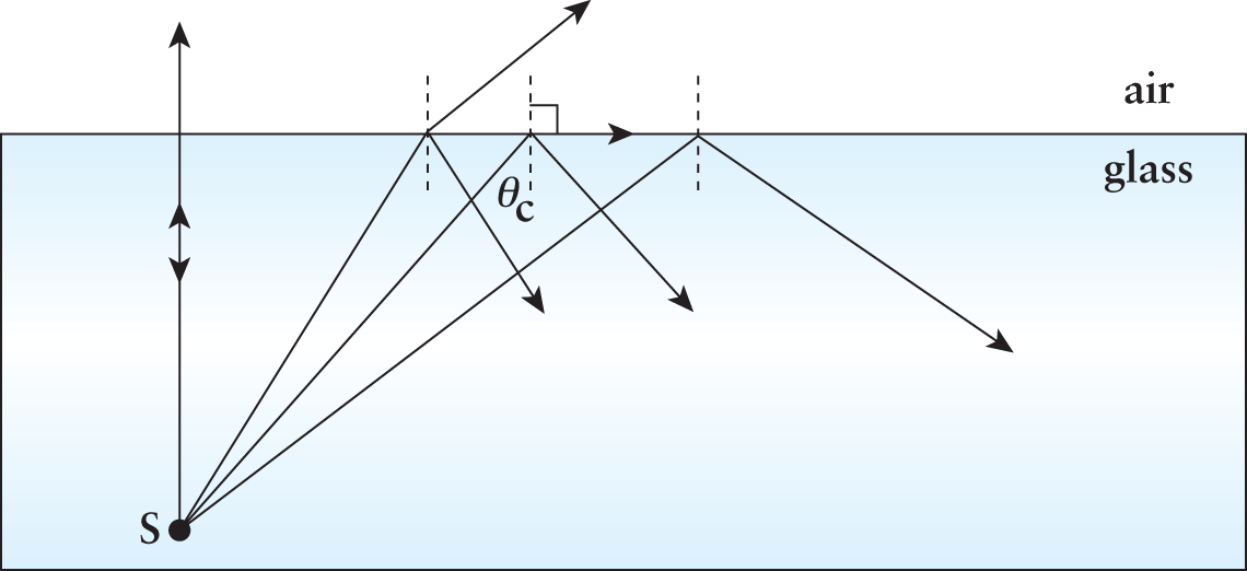
Total internal reflection occurs as the light moves from a medium with a higher refractive index to a medium with a lower one.
There is an important difference between lenses and mirrors, aside from the fact that lenses refract light while mirrors reflect it. When working with lenses, there are two surfaces that affect the light path. For example, a person wearing glasses sees light that travels from an object through the air into the glass lens (first surface). Then the light travels through the glass until it reaches the other side, where again it travels out of the glass and into the air (second surface). The light is refracted twice as it passes from air to lens and from lens back to air.
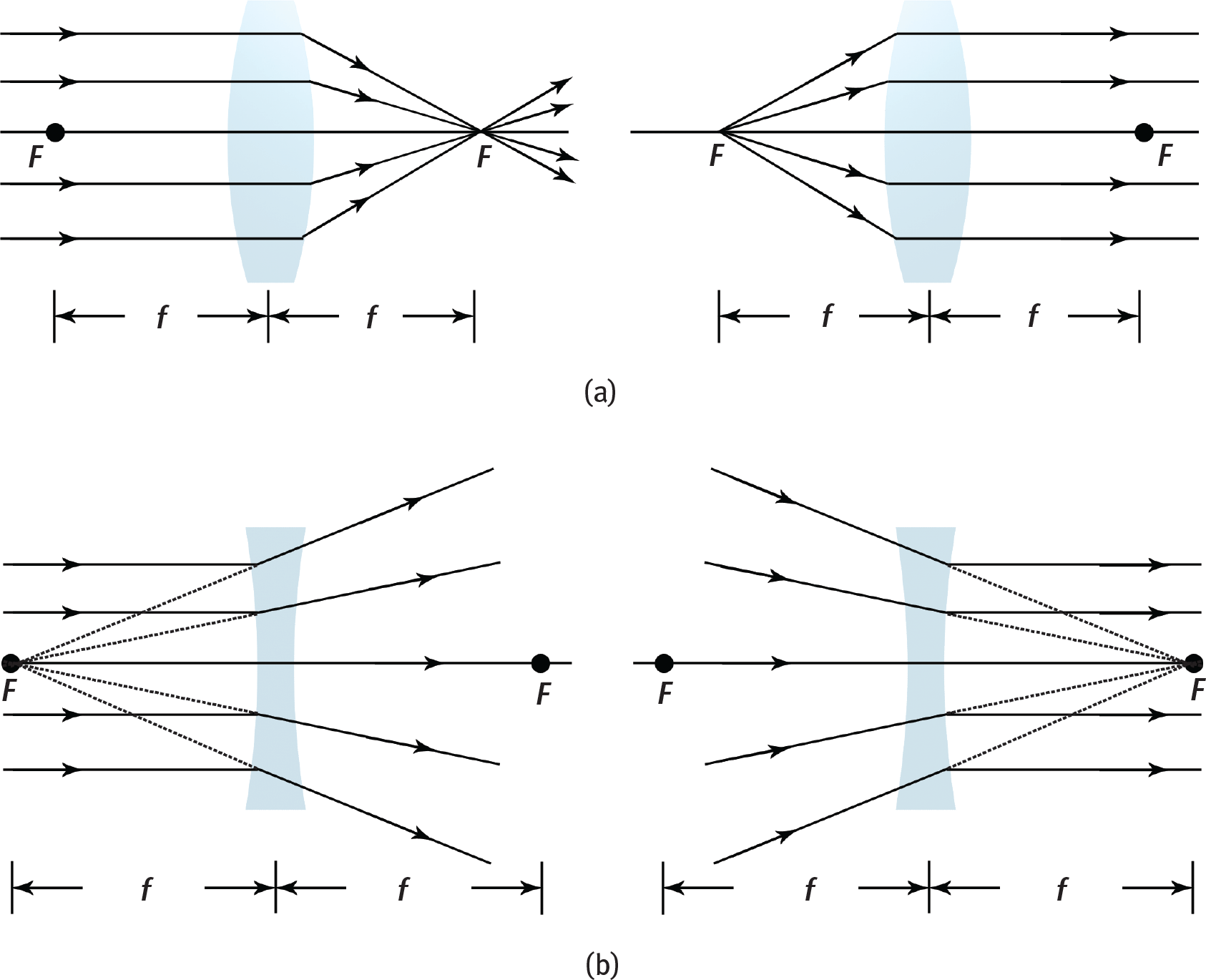
On the MCAT, lenses generally have negligible thickness. Because light can travel from either side of a lens, a lens has two focal points, with one on each side. The focal length can be measured in either direction from the center. For thin spherical lenses, the focal lengths are equal, so we speak of just one focal length for the lens as a whole.
Figure 8.11a illustrates that a converging lens is always thicker at the center, while
Figure 8.11b illustrates that a diverging lens is always thinner at the center. The
basic formulas for finding image distance and magnification for spherical mirrors
also apply to lenses. The object distance o, image distance i, focal length f, and magnification m, are related by the equations
 and
and

Converging lenses (reading glasses) are needed by people who are “farsighted.” Diverging lenses (standard glasses) are needed by people who are “nearsighted.”
For lenses where the thickness cannot be neglected, the focal length is related to the curvature of the lens surfaces and the index of refraction of the lens by the lensmaker’s equation:
where n is the index of refraction of the lens material, r1 is the radius of curvature of the first lens surface, and r2 is the radius of curvature of the second lens surface.
The eye is a complex refractive instrument that uses real lenses. The cornea acts as the primary source of refractive power because the change in refractive index from air is so significant. Then, light is passed through an adaptive lens that can change its focal length before reaching the vitreous humor. It is further diffused through layers of retinal tissue to reach the rods and cones. At this point, the image has been focused and minimized significantly, but is still relatively blurry. Our nervous system processes the remaining errors to provide a crisp view of the world.
To find where the image is (for a lens), draw the following rays and find a point where any two intersect. This point of intersection marks the tip of the image. If the rays you draw do not appear to intersect, extend them to the same side of the lens from which the light came, creating a virtual image.
Note that the sign conventions change slightly for lenses. For both lenses and mirrors, positive magnification represents upright images, and negative magnification means inverted images. Also, for both lenses and mirrors, a positive image distance means that the image is real and is located on the real (R) side, whereas a negative image distance means that the image is virtual and located on the virtual (V) side. Table 8.3 summarizes the sign conventions for single lenses.
| Symbol | Positive | Negative |
| o | Object is on same side of lens as light source | Object is on opposite side of lens from light source (extremely rare) |
| i | Image is on opposite side of lens from light source (real) | Image is on same side of lens as light source (virtual) |
| r | Lens is convex (converging) | Lens is concave (diverging) |
| f | Lens is convex (converging) | Lens is concave (diverging) |
| m | Image is upright (erect) | Image is inverted |
It is important to realize that concave mirrors and convex lenses are both converging and thus have similar properties. Convex mirrors and concave lenses are both diverging and also have similar properties.
The designations of real and virtual are often a point of confusion for students because they are on opposite sides when comparing mirrors and lenses. To identify the real side (R), remember that the real side is where light actually goes after interacting with the lens or mirror. For mirrors, light is reflected and, therefore, stays in front of the mirror. Hence, for a mirror, the real side is in front of the mirror, and the virtual side is behind the mirror. For lenses, the convention is different: because light travels through the lens and comes out on the other side, the real side is on the opposite side of the lens from the original light source, and the virtual side is on the same side of the lens as the original light source. Although the object of a single lens is on the virtual side, this does not make the object virtual. Objects are real, with a positive object distance, unless they are placed in certain multiple lens systems in which the image of one lens becomes the object for another (a scenario which is very rarely encountered on the MCAT).
Focal lengths and radii of curvature have a simpler sign convention. For both mirrors and lenses, converging species have positive focal lengths and radii of curvature, and diverging species have negative focal lengths and radii of curvature. Remember that lenses have two focal lengths and two radii of curvature because they have two surfaces. For a thin lens where thickness is negligible, the sign of the focal length and radius of curvature are given based on the first surface the light passes through.
Optometrists often describe a lens in terms of its power (P). This is measured in diopters, where f (the focal length) is in meters and is given by the equation
P has the same sign as f and is, therefore, positive for a converging lens and negative for a diverging lens. People who are nearsighted (can see near objects clearly) need diverging lenses, while people who are farsighted (can see distant objects clearly) need converging lenses. Bifocal lenses are corrective lenses that have two distinct regions—one that causes convergence of light to correct for farsightedness (hyperopia) and a second that causes divergence of light to correct for nearsightedness (myopia) in the same lens.
The MCAT does expect students to understand what myopia and hyperopia are, as well as their corresponding ray diagrams and correction strategies.
Lenses in contact are a series of lenses with negligible distances between them. These systems behave as a single lens with equivalent focal length given by
Because power is the reciprocal of focal length, the equivalent power is
The eye has an optical power of around 60 diopters. Most contact lens wearers have prescriptions between 0.25 and 8 diopters (both positive and negative). Therefore, even at its worst, the human eye can maintain its optical power at about 87% of its maximum.
A good example of lenses in contact is a corrective contact lens worn directly on the eye. In this case, the cornea of the eye (a converging lens) is in contact with a contact lens (either converging or diverging, depending on the necessary correction), and their powers would be added.
For lenses not in contact, the image of one lens becomes the object of another lens. The image from the last lens is considered the image of the system. Microscopes and telescopes are good examples of these systems. The magnification for the system is
Because the MCAT is a timed test, you will not be given a massive multiple lens system and be expected to make calculations, although they might test a multiple-lens system conceptually.
Spherical mirrors and lenses are imperfect. They are therefore subject to specific types of errors or aberrations. Spherical aberration is a blurring of the periphery of an image as a result of inadequate reflection of parallel beams at the edge of a mirror or inadequate refraction of parallel beams at the edge of a lens. This creates an area of multiple images with very slightly different image distances at the edge of the image, which appears blurry. This phenomenon can be seen in Figure 8.12.
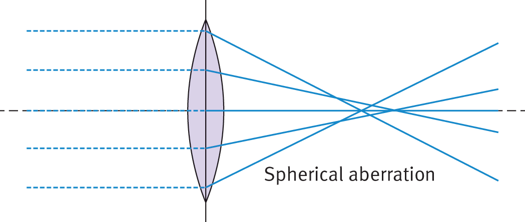
If you remember back to conic sections from your precalculus class, it should be no surprise that spherical mirrors and lenses do not focus light perfectly. Parabolas are perfect reflectors, meaning that parallel light rays are reflected perfectly through the focal point. This is used in extracorporeal shock wave lithotripsy, in which a parabolic mirror is positioned with a kidney stone at the focal point. Sound waves are reflected off of the mirror and create enough vibration in the kidney stone to shatter it.
Chromatic aberration, discussed below, is predominantly seen in spherical lenses.
As discussed earlier, the speed of light in a vacuum is the same for all wavelengths.
However, when light travels through a medium, different wavelengths travel at different
speeds. This fact implies that the index of refraction of a medium affects the wavelength
of light passing through the medium because the index of refraction is related to
the speed of the wave by
 It also implies that the index of refraction itself actually varies with wavelength.
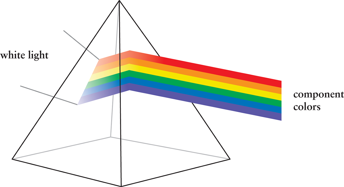
When various wavelengths of light separate from each other, this is called dispersion. The most common example of dispersion is the splitting of white light into its component
colors using a prism.
It also implies that the index of refraction itself actually varies with wavelength.
When various wavelengths of light separate from each other, this is called dispersion. The most common example of dispersion is the splitting of white light into its component
colors using a prism.
If a source of white light is incident on one of the faces of a prism, the light emerging from the prism is spread out into a fan-shaped beam, as shown in Figure 8.13. This occurs because violet light has a smaller wavelength than red light and so is bent to a greater extent. Because red experiences the least amount of refraction, it is always on top of the spectrum; violet, having experienced the greatest amount of refraction, is always on the bottom of the spectrum. Note that as light enters a medium with a different index of refraction, the wavelength changes but the frequency of the light does not.
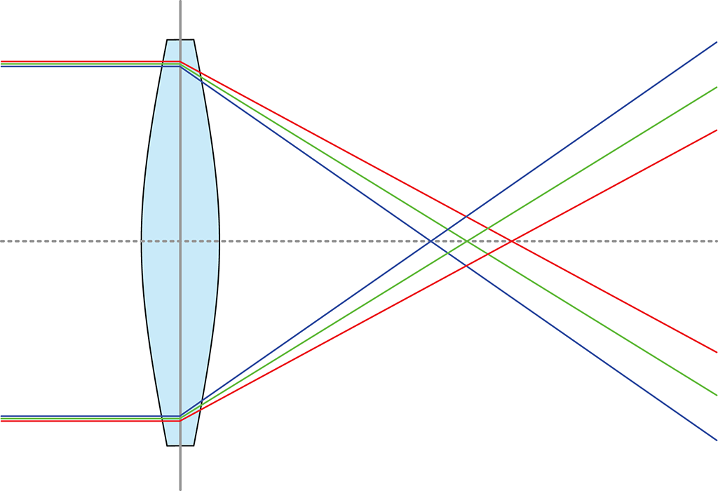
Chromatic aberration, shown in Figure 8.14, is a dispersive effect within a spherical lens. Depending on the thickness and curvature of the lens, there may be significant splitting of white light, which results in a rainbow halo around images. This phenomenon is corrected for in visual lenses like eyeglasses and car windows with special coatings that have different dispersive qualities from the lens itself.