CHAPTER VII
MISCELLANEOUS TOOLS
CONTINUED
Mending a Vise.
I will make a few remarks about the vise, a tool which blacksmiths use every day. Some smiths believe that when the threads or screws are worn out, it is necessary to buy a new vise. But this is an error; for the old vise can be mended so as to be as good as a new one. The job is done as follows:
First cut the old vise screw off where the screw stops, or about two inches from the collar of the large end, then weld on a new piece of round iron and turn threads on it the same as if for a new vise screw. To get them in line these threads should be done with a lathe. It is better to have the screws taper slightly. The next thing in order will be to get the screw threads in the box. First, take a drill and turn the old threads out, smoothly and true. Care must be taken to have a space of at least 3/16 of an inch all round the screw when it is placed in the threadless box. Then take a long piece of Swedish iron just thick enough to be bent in the screw, and about 3/16, or a fraction under, than the depth of the threads on the screws. Bend this flat iron from one end of the screw to the other, then make another piece of iron that will fit in the screws that the first piece of iron left after it was bent. This second piece we find will be as thick as the screws on the vise screw, and as wide as the first piece extends above the screws. This being done, all is closed up smooth, the second piece holding the main threads firm after the screw is turned out. Now the threads are on the vise screw, and it is nearly ready to be put in the box. First dress the outside of the threads off, so the screw can be driven in the box when it is a little warm, then drive screw threads all into the box at about the place where they belong, then let the box cool, and turn the screw out of the threads and braze the screws; put the brass on end side. When you are melting it, keep turning the box so it will be brazed all over. When cool, grease the screw and threads well and slowly turn it in. The main thread must not fit too tightly in the screws. This makes the best vise screw. By measuring the depth of the hole in the box you can tell how long to make the threads on the screw.—By J. W.
A Cheap Reamer.
The following may be an old idea, though I have discovered it for myself: Heat an old three-cornered file; hammer one corner down, then grind the same round and the other corner sharp, temper, and you have a cheap taper reamer, cutting both ways.—By WILL TODD.
Shapes of Lathe Tools.
Every toolsmith knows the trouble he has to contend with in tool dressing. One man wants a tool this shape, another a different shape. One wants his tools fully hardened, while another prefers a straw temper. Of course, in a shop large enough to keep a toolsmith for this special work, the smith makes the tools to the shape he has found by experience to be the most suitable for general work, only varying it to suit some special occasion.
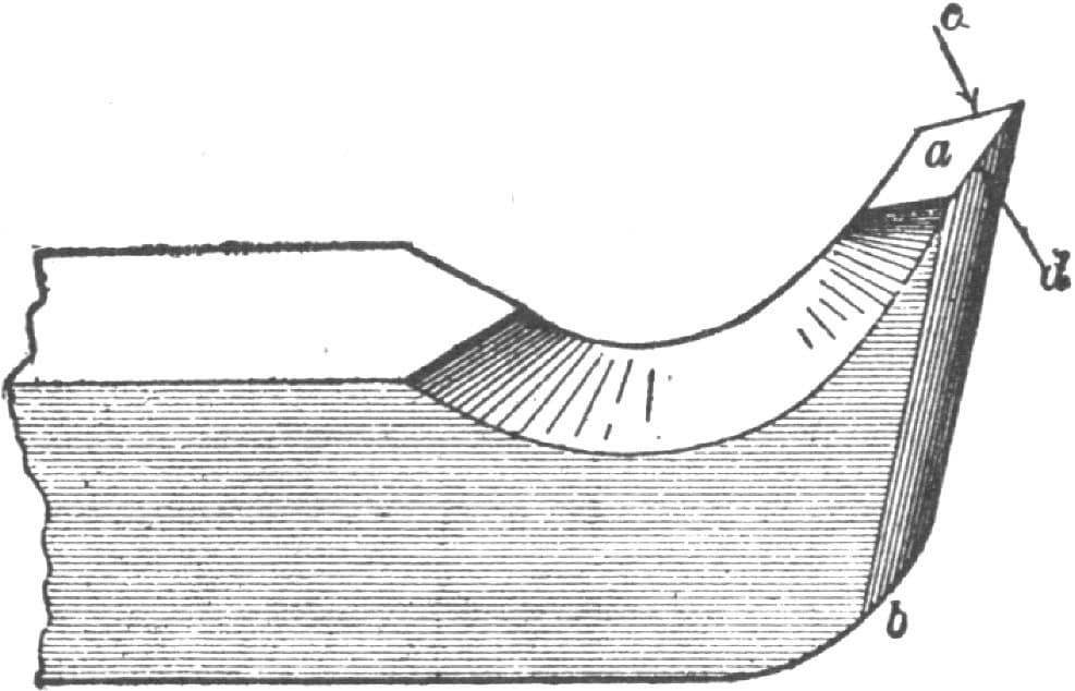
The Shape and Use of Cutting Tools for Lathes. Fig. 137—The Diamond Point Tool
But in a small shop tool forging becomes a part of the duty of the ordinary blacksmith, and in order that he may know what shapes tools should be given he must understand the principles governing their action. These principles I will now explain so plainly and carefully that no one can fail to comprehend them.
Fig. 137 of the accompanying illustrations represents what is commonly called the diamond-point tool, a being its top face, b its bottom one, and c and d the cutting edges. This is a very common form of tool, but I do not believe it is the best one even for the purpose of plain outside turning, a much easier tool to forge and to grind being the one shown in Fig. 138. The rake of the top face is its angle in the direction of the arrow in Fig. 139, and the rake of the bottom face b is its angle in the direction of the arrow in Fig. 140.
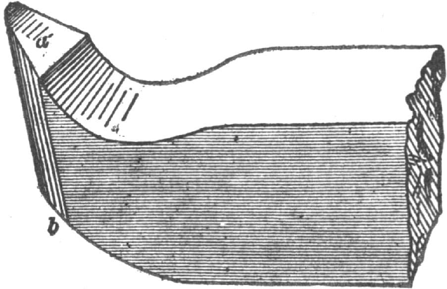
Fig. 138—Showing a Tool Easy to Forge and Grind
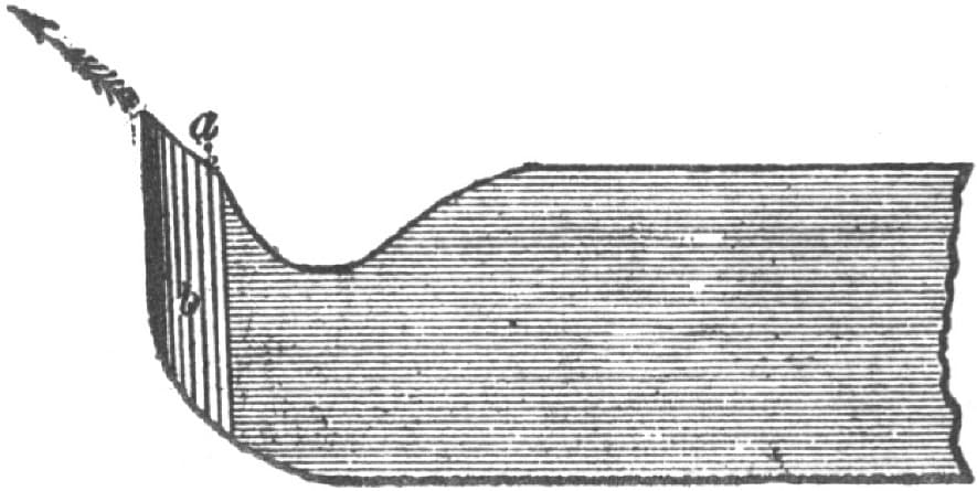
Fig. 139—Showing the Rake of the Top Face
The efficiency and the durability of the cutting edge depends upon the degrees of rake given to these two faces. Obviously the less rake the stronger the cutting edge, but the less keen the tool.
If we give a tool an excess of top rake, as in Fig. 141, the cutting edge will soon dull, but the cutting C will come off clean cut and in a large coil, if the tool is fed into the work. The strain on the top face, however, will be in the direction of D, and the tool will be liable to dip into the cut when the cut deepens, as it will in some places on account of a want of roundness in the iron.
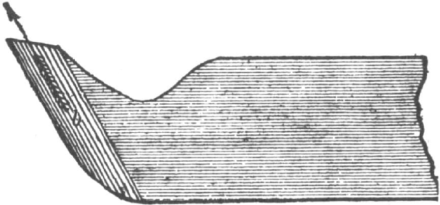
Fig. 140—Showing the Rake of the Bottom Face
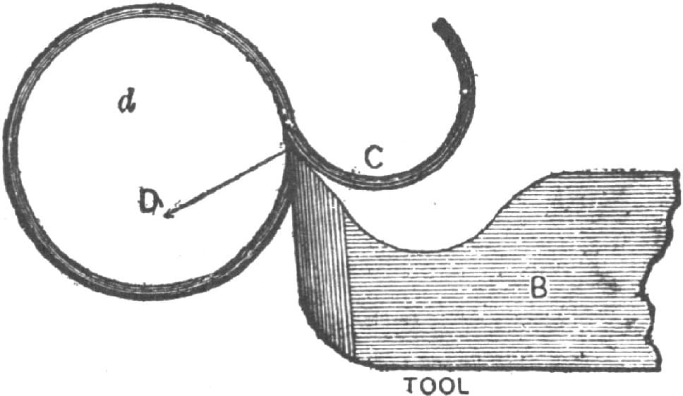
Fig. 141—Showing a Tool with an Excess of Top Rake
If, on the other hand, we give too much bottom rake, as in Fig. 142, the cutting edge will be weak, and there being but little top rake, the pressure will be in the direction of D. Furthermore, the cutting will come off in almost straight pieces and all broken up. A fair amount of top and bottom rake for wrought iron is shown in Fig. 143, the top rake being diminished for cast iron and for steel.
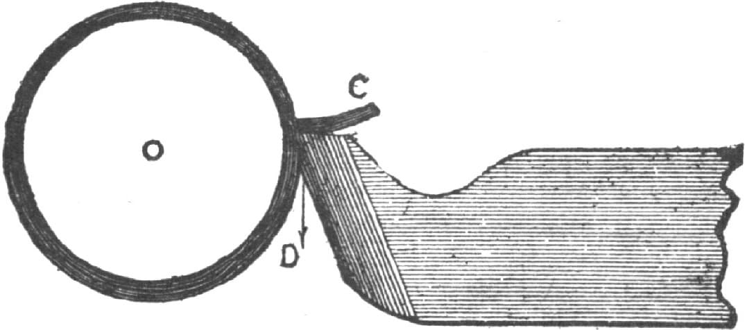
Fig. 142—Showing a Tool with too much Bottom Rake
The best guide as to the efficiency of a tool is its cuttings or chips, as they are commonly called. When the tool is fed upward only, the cutting should come off in a large circle as in Fig. 141, and if the coil is small there is insufficient top rake. But when fed level along the work the cutting comes off in a spiral, such as in Fig. 144. The more top rake the tool has the more open the coils will be, the cutting shown being as open as it should be even for the softest of wrought iron. The harder the metal the less top rake a tool should have, while the bottom rake should in all cases be kept as small as possible, say 10 degrees for the rate of feed of an average 16-inch lathe. The tool point should never stand far above the top of the tool steel, the position shown in Fig. 138 being for a newly forged tool.
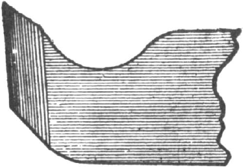
Fig. 143—Showing a well proportioned Tool for Wrought Iron
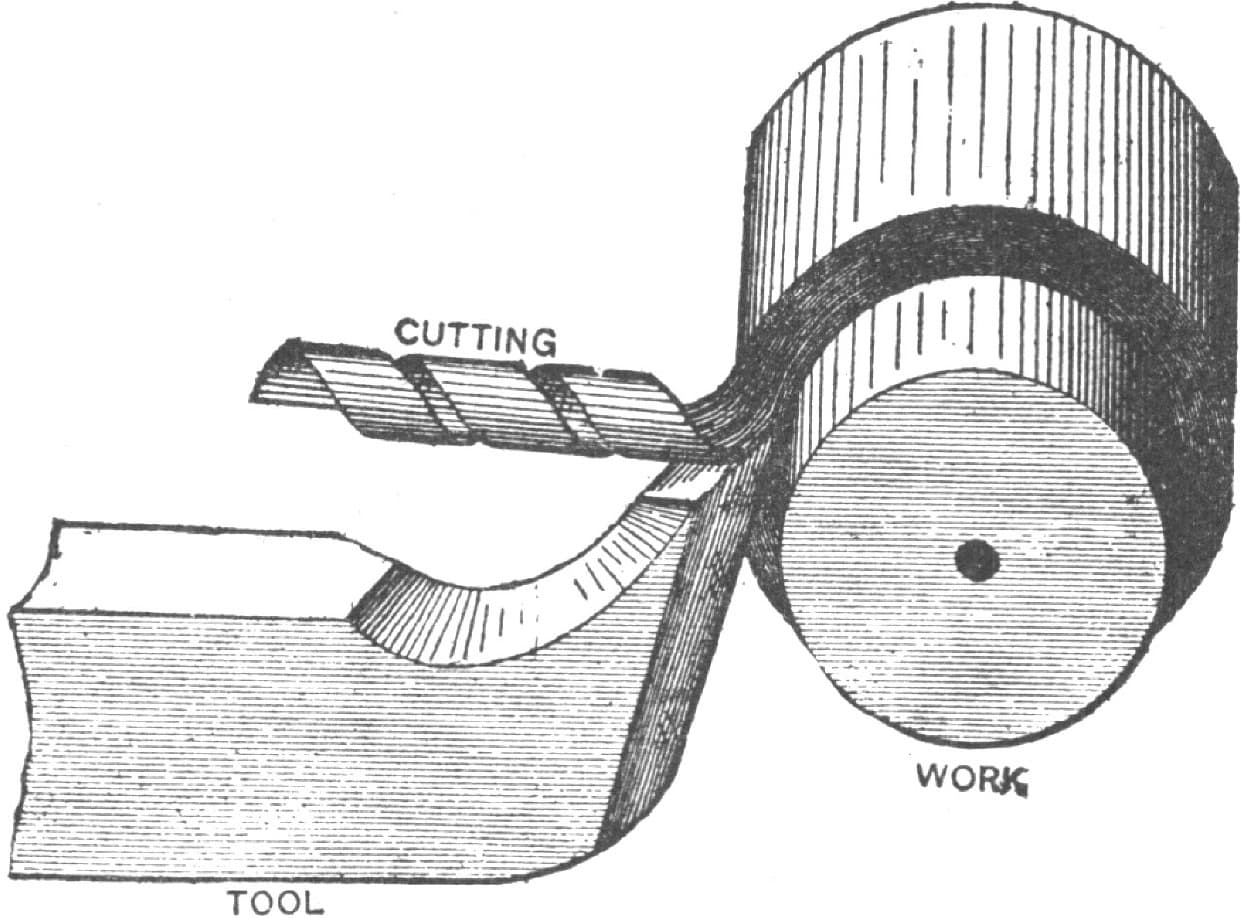
Fig. 144—Showing how the Cutting comes off when the Tool is fed Level
The practiced hand may have these tools fully hardened, but the beginner should temper them to a light straw color.
The top of anvil should be perfectly level and smooth, and the center of the same should be harder than the edges, because it receives the brunt of the blows. When used on the upper floors of a building, when a solid foundation can not be had, resort is had to a device by means of which the jar of the blows is obviated. This consists in mounting the anvil upon a stout spring whose upward rebound is counteracted by smaller springs placed above.—By JOSHUA ROSE.
Useful Attachment to Screw Stock Dies.
Having an order to fill for a small quantity of iron pins 21/2 by 1/8 inch in diameter, to be threaded at each end with a wood screw thread, and having no tools to cut the threads with, I devised and used the following plan, which answered so satisfactorily that I think the idea may be of service to others, and hence send you sketches of it.
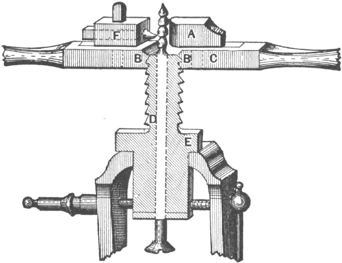
Fig. 145—Attachment to Screw Stock Dies as designed by “W. D.” Side View
C, in Fig. 145, is the die stock having in it the dies B B, with the requisite pitch of thread. On the die stock is fastened a tool post and tool at F and a copper steadying piece at A. The tool may be made from 1/4-inch square Stubbs or Crescent steel carefully filed to the shape of the thread to be cut and carefully tempered. E is a steel sleeve screwed with a thread of the same pitch and sawn through its axis one way to point D, and the spring tempered in oil. The pin to be threaded is inserted through the sleeve E, which on being gripped in the vise securely holds the pin. When the stock is revolved E regulates the pitch of the thread that the tool will cut on the pin. Hence the stock may be used in the ordinary manner. A plan view is shown in Fig. 146. If many bolts are wanted it would be well to make a pair of blank or soft dies or otherwise a piece of thin sheet-brass between the dies, and the sleeve will be of service. I may state that the thread cut by this tool when well made, is equal to any wood screw, whether made of iron, steel, or manufactured brass. —By W. D.
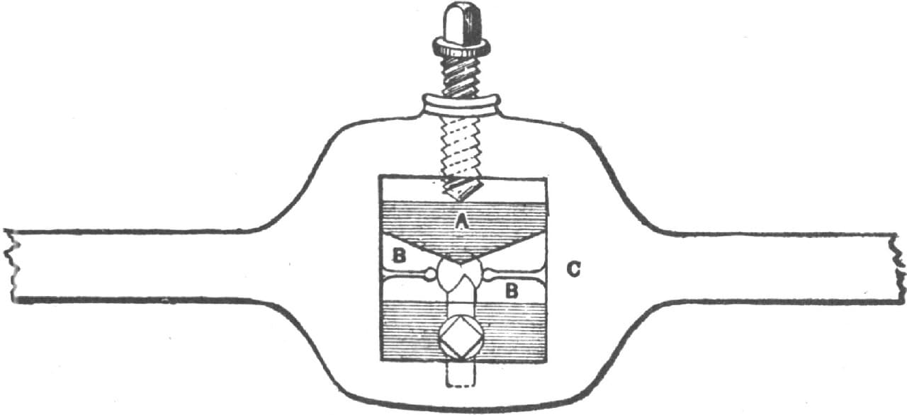
Fig. 146—Plan View of “W. D.’s” stock
Wear of Screw-Threading Tools.
It is well-known that a tap can be sharpened by grinding the tops of the teeth only, and since the reason of this explains why the work goes together tighter as the tools wear, permit me to explain it. In Fig. 147, which presents a section of the tap, A B are the top corners and E F the bottom corners of the thread. Now, as the thread is formed by cutting a groove, and the teeth cut the groove, it is evident that A B cut continuously, but as E F do not meet the work until the thread is cut to its full depth, they do no cutting, providing the tapping hole is the right size, as it should be. It follows then that the corners A B wear the most, and like all sharp corners they wear rounding.
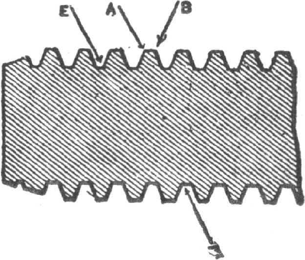
Fig. 147—Section of Tap showing Wear of Screw-Threading Tools
Now take the case of the die in Fig. 148, and it is evident that the corners C D do the cutting, and, therefore, wear rounding more than the corners G H, which only meet the work when it has a full thread cut on it. Now take a bolt and nut with a thread cut on it by worn dies, and we shall have the condition of things shown in Fig. 149; rounded corners at A B on the nut and at C D on the bolt, and sharp corners at E F on the nut and at G H on the bolt. Hence corners G H jam against corners A B, and corners E F jam against corners C D. So much for the wear, and now for the sharpening of the tap. It is evident that as the tops of the teeth do the main part of the cutting, they get dull quickest, and therefore by grinding them the teeth are greatly sharpened.—By J. R.
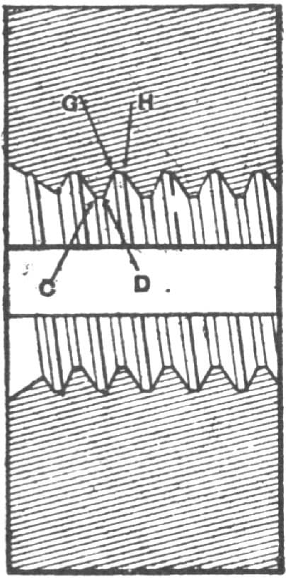
Fig. 148—Section Through a Die
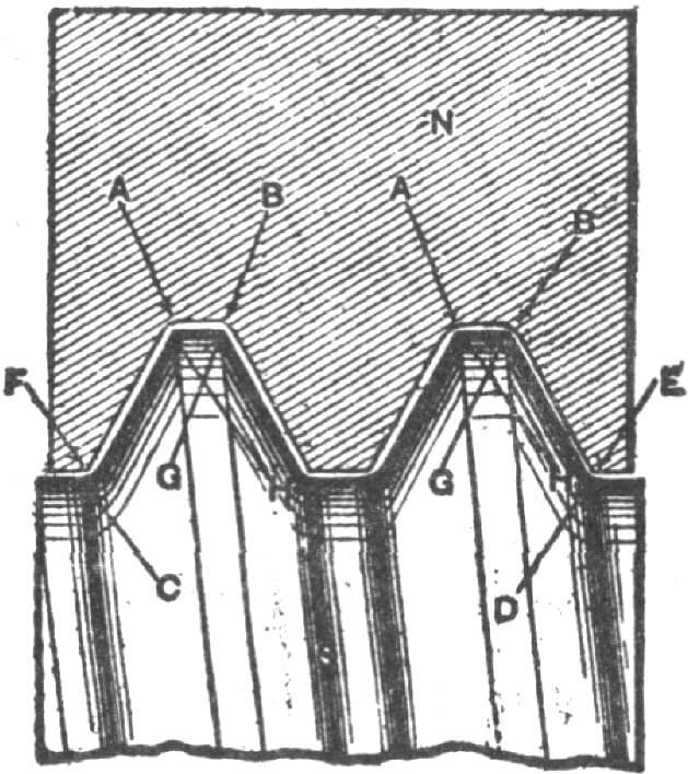
Fig. 149—Enlarged Section Through a Bolt and Nut cut by Worn Dies
Tool for Wagon Clips.
The following tool for use in bending buggy, saddle and wagon clips, is easily made and will save much time where a number of clips are used. Figs. 151 and 152 show the tool taken apart. In making it have the width from axle to axle the required width of the clip, and have the part A so that it will fit up tight in the slot H. The part B, shown in Fig. 151, is of the same width as A. Fig. 150 shows the tool put together with the clip fastened in it ready for bending. In bending clips in a tool of this kind, they can be formed half round, if desired. Round and square iron may be used as required. In using the tool proceed as follows: Place A, of Fig. 151, in the slot H, then place the clip in the slot at O. Next drive the wedge-shaped key D in the slots of C and B. When the clip is fastened in the tool, as shown in Fig. 150, with a hand hammer bend the ends against the parts F F of the tool. In taking the clip out of the tool drive the pin out of the slots and drive the clevis from the mandrils. At this stage the clip will be finished, or in other words it will be shown in the shape as shown at C and ready for swedging the parts for the nuts. By a little practice any smith will be able to bend nearly a square corner on the outside of the clip.—By H. R. H.
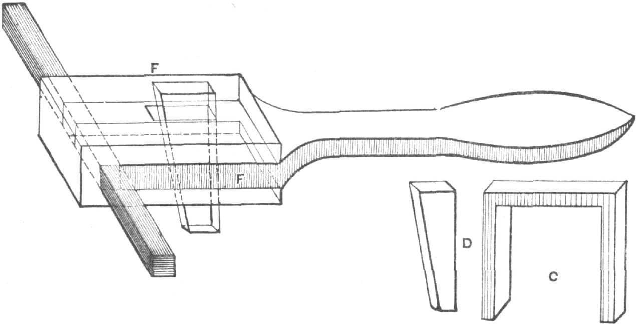
Fig. 150—Device for Bending Clips, with Detail of Wedge and a View of a Finished Clip

Fig. 151—The Principal Part of the Tool
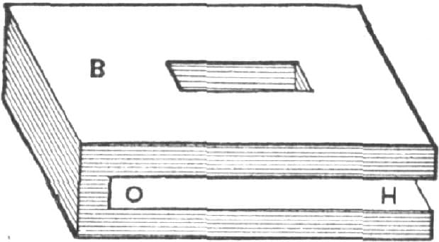
Fig. 152—Detail of the Clamping Device
A Handy Tool.
Many times, in taking old carriages apart, considerable trouble arises from the turning of bolts, as the small square under the head will not hold the bolt if the nut turns hard. In such cases it is usually necessary to split the nut, to get the bolt out. The tool in question will save many bolts and much vexation of spirit. Set the jaws down over the head B of the bolt, Fig. 153, strike on the top of the jaw at A with a hammer to settle into the wood; then pinch the handles and you have it held fast, and the nut can then be readily turned off. The tool is about 10 inches long, and 5/8 to 3/4 of an inch in thickness, measuring through the points joined by the rivet. It will work on bolts from 3/16 to 3/8, and even larger. A blacksmith can make a pair in one hour, and save many hours of valuable time. For the want of a better name we call it a “Polly.”—By O. F. F.
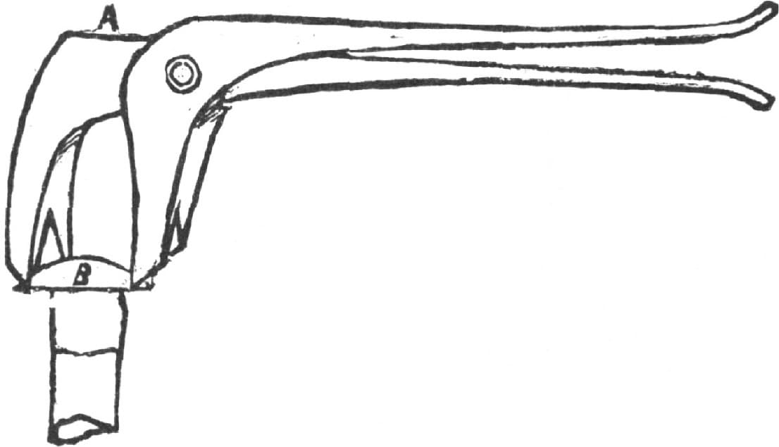
Fig. 153—A Handy Tool
False Vise-Jaws for Holding Rods, etc.
Here is a simple device for holding bolts in a vise. Though an old invention it is not as well-known as it ought to be. Fig. 154 of the illustration shows the end of a pair of cast-brass jaws fitting on the vise. Fig. 155 shows one jaw. The same pattern will do for both. Clamp the jaws and drill the holes, filing them afterward to the shape desired. Square holes are most useful, as they hold both round and square rods. Do not make the holes larger than need be, and then they may be redressed when worn, or altered to suit new work.—By WILL TOD.
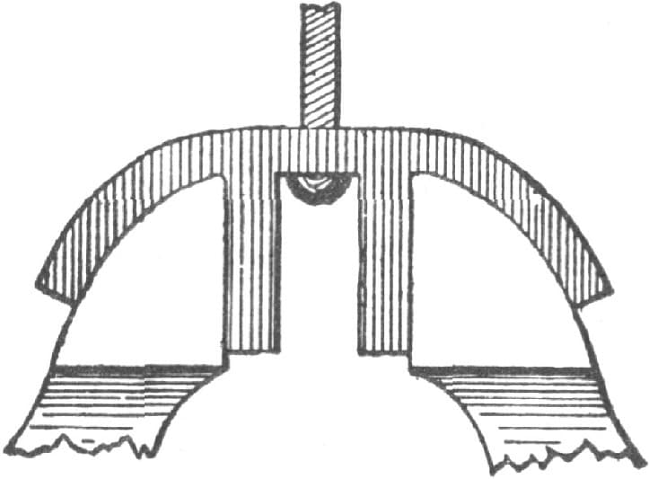
Fig. 154—False Vise-Jaws. End View
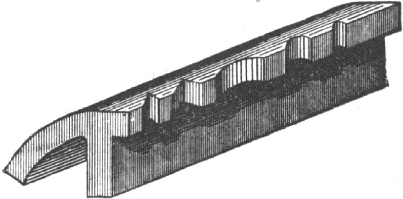
Fig. 155—Showing one of the Jaws
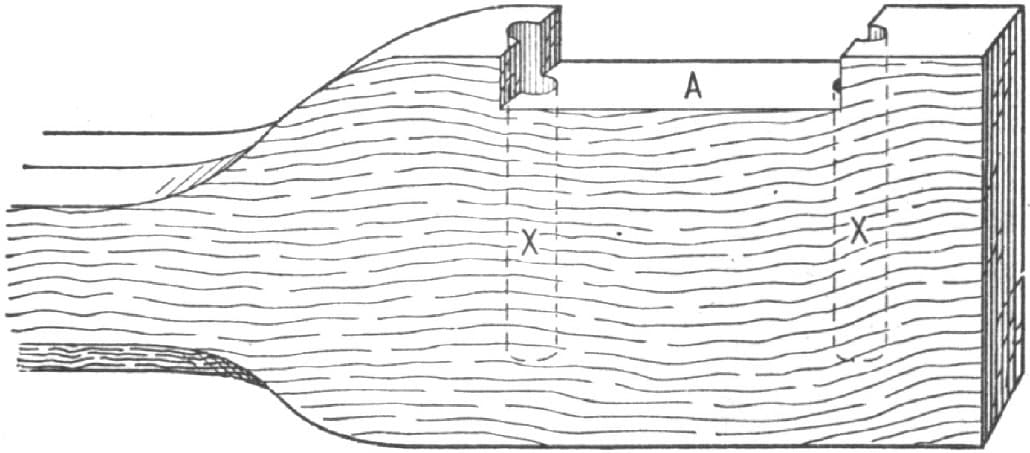
Fig. 156—The Bottom Tool for Making Spring Clips
Making Spring Clips with Round Shanks and Half-Round Top.
The accompanying illustrations represent my method of making short spring clips. The bottom tool shown in Fig. 156, should have a handle about 12 inches long. To make this tool take cast steel, say 3 × 1 inches, and first forge out the handle, then drill the two holes X X. These holes should be for 5/16 iron, and drilled with a 11/32 drill as deep as the shaft required is long, and should never be drilled through the tool, but made as shown in Fig. 157 by the dotted lines XX. Fig. 159 represents the top swage. This is made of cast steel, the same as any common top swage. First cut out the impression C the full length of the tool, then cut down the recess B B, then punch out the eye D for the handle. This top swage is made to fit the bottom swage or handle tool, Fig. 156. To make the clips proceed as follows: Cut 5/16 inch round iron the proper length, bend it as shown in Fig. 157, place it in the tool, Fig. 156, set the swage, Fig. 159, on top of the iron, and with five or six blows from the sledge you get the clip with both corners bent, as shown in Fig. 158. Any smith after two or three trials will know just how long to cut the iron to get the best results. The tool must be kept cool, for when it gets hot it will stick the clip.—By H. R. H.
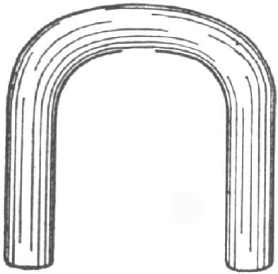
Fig. 157—Showing how the Clip is Bent
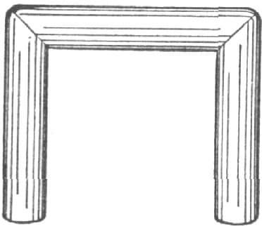
Fig. 158—The Finished Clip
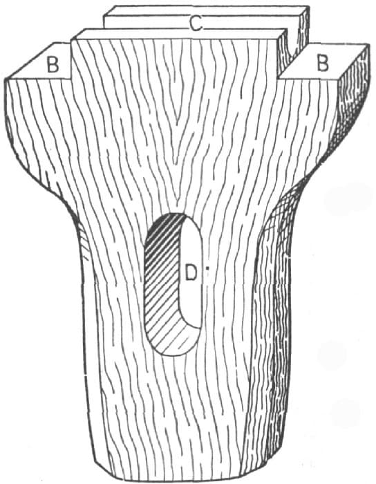
Fig. 159—The Top Tool used in Making Spring Clips
Handy Tool for Marking Joints.
Not wishing to secure everything and give nothing in return, I send you a sketch, Fig. 160, of a handy tool to mark off joints where one cylindrical body joins another. A is a stem on a stand E. A loose sleeve, B, slides on A carrying an arm C, holding a pencil at D. A piece of truly surfaced wood or iron, W, has marked on it the line J. Two Vs, G G, receive the work P. Now, if the centers of G G and of the stand E all coincide with the line J, then E will stand central to P, and D may be moved by the hand around, P being allowed to lift and fall on A so as to conform to the cylindrical surface of P, and a line will be marked showing where to cut away the wood on that side, and all you have to do is to turn the work over and mark a similar line diametrically opposite, the second line being shown at K.—By S. M.
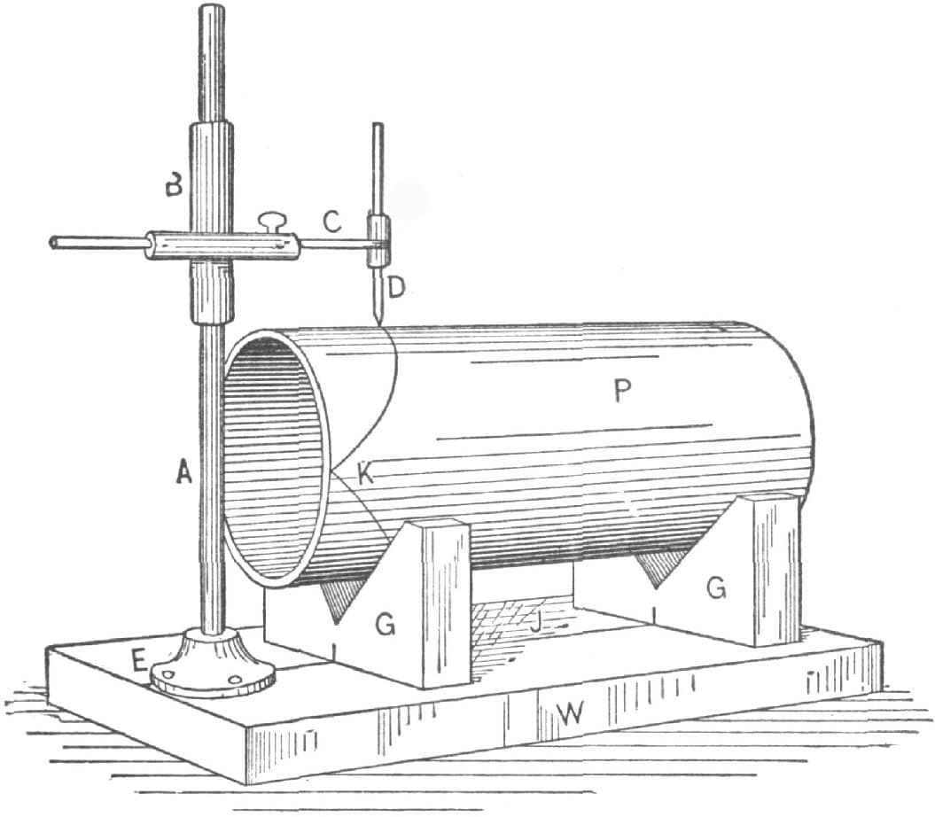
Fig. 160—Handy Tool for Marking Joints
Tools for Holding Bolts in a Vise.
I send sketches of what I find a very handy tool for holding bolts or pins. It consists of a spring clamp that goes between the vise jaws, as in Fig. 161 of the accompany engravings, and has a groove in its jaws to hold the round stems of bolts to the vise jaws, without damaging the heads. It may be made also, as in Fig. 162, with a hole on its end as well to hold round pins. It doesn’t fall off the vise as other clamps do.—By W. S. H.
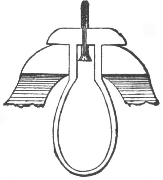
Fig. 161—Showing how the Bolt is held by device of “M. S. H.”
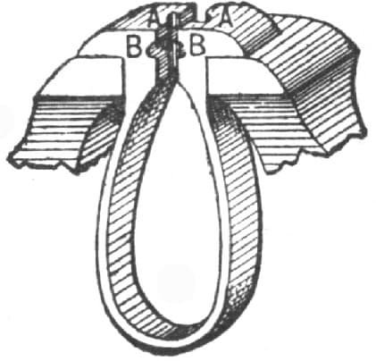
Fig. 162—Showing the Device adapted for Holding Round Pins
A Tool for Making Singletree Clips.
I have recently devised a simple tool for making singletree clips from a single heat and will endeavor to explain how it is made.
Proceed the same as in making any kind of a bottom swage, that is, take a piece of square iron the size of the hole in the anvil, and upset one end sufficiently for welding, then take another piece of iron 1/8-inch thick by 21/2 inches wide and 81/2 inches long and draw the ends down to the shape shown in Fig. 163 of the accompanying illustrations. Upset in the center, or, if your anvil is small, a little to one side of the center, or enough so that when your swage is in place, the end will not project over the end of the anvil. Weld on the stem and fit to the anvil. Next, make two 1/2-inch grooves in each end of the swage commencing near the end and pointing to the center, as shown in Fig. 164. Have the measurements as near as possible to the following: From A to B, 8 inches; from C to D, 11/2 inches. Next, take a piece of iron 1 × 11/4 inches and weld on the ends of the swage, extending over the swage about 1/4 of an inch. Open up the ends of the grooves and the tool is ready for use, as in Fig. 165.

Fig. 163—Showing How the Ends are Shaped

Fig. 164—Showing How the Grooves are Made
To make the clips take 1/2-inch round iron, cut off 81/2 inches long, heat in the center and bend sufficiently to allow it to go in the tool, then flatten the center, take the clip out and bend it over the horn into shape. A smith can easily make a clip at each heat. Of course, for making clips of different sizes the tool must be made accordingly.—By J. W. C.
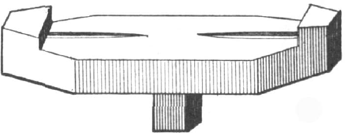
Fig. 165—The Finished Tool
Tool for Making Dash Heels.
I send sketches of a tool for making dash-heels for buggies or phaetons, and will attempt to describe the manner of making and using the tool. Fig. 166 represents the article. It is made of cast steel as far as the dotted line shown to the right. At this point is welded on a piece of 7/8-inch round iron for the handle. The tool proper is four inches long, and the handle twelve inches long. The thickness or depth of the tool is two and one-half inches. It is made wider at the bottom than at the top. Through the center of the tool, as shown in Fig. 166, a hole is made, passing from face to face. This hole is 7/8 by 5/8 inch, which adapts the tool to making a heel of these dimensions. This weight is ample for a piano box, or phaeton body. The oval cavity in the upper face of the tool is five-eighths of an inch deep.

Fig. 166—Tool for Making Dash Heels. General Appearance of the Tool
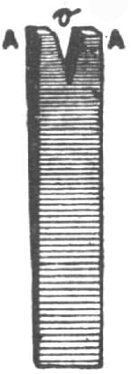
Fig. 167—Tapering and Splitting the Piece of Iron to form the Article
The manner of using the tool is as follows: Use Norway iron, 7/8 × 1/2 inch in size, and draw it out wedge shape, as indicated in Fig. 167, heat the end marked A A, and place the iron in the tool; let the helper strike it four or five blows with the sledge; next take a splitting chisel and while the iron is in the tool, split it, as shown in Fig. 167 at O; replace the iron in the fire, and obtaining a good welding heat, put it in the tool again and hammer down the split ends in the oval part of the tool. With the same heat edge up the iron; this is done by letting the piece come up two or four inches in the tool, and holding it with the tool while edging it up. With the same heat also knock the iron down into the tool and swage with a top oval swage to match the oval of the tool. Take the iron out. It will be found that a heel has been formed as shown in Fig. 168. If the heel is required for a phaeton body, all that remains to be done is to punch the holes; if, on the other hand, however, the heel is wanted for a piano-box or any other body with a panel in the front, it is necessary to bind the corner A, Fig. 168, as shown by the dotted lines.
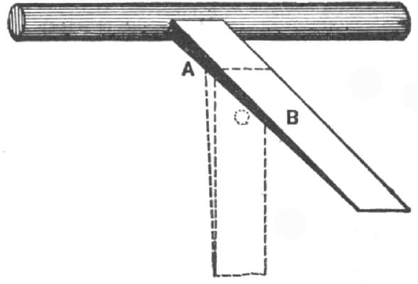
Fig. 168—Appearance of the Article upon Removing from the Tool
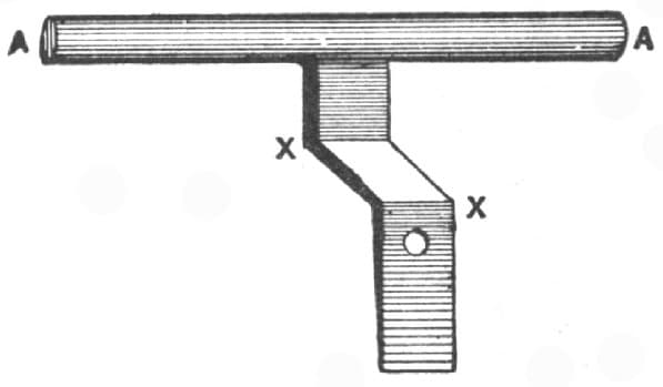
Fig. 169—Form of the Article Made in the Old Way
The old way of forging a dash heel was to split it, forge and swage the oval ends A A, Fig. 169, and then bend the corners as shown by X X in the same figure. By forging a dash heel with the tool above described, bending one corner is saved, and the piece, when finished, does not set up like a stilt. The oval iron comes down on to the body. In fastening the dash to the body always let the oval iron project one-eighth of an inch beyond the edge, so as to have the leather of the dash lie straight against the edge of the body. For making the bend A in Fig. 168, I use a pair of tongs shown in Fig. 170. The lower jaw is one inch in depth and the upper jaw 11/8 inches. The length of the jaws is four inches, and their width 11/8 inches. The manner of using these tongs is so evident upon inspection of the sketch that further explanation is unnecessary.—By H. R. H.

Fig. 170—Tongs for Making the Bend shown at A in Fig. 168
Mending Augers and other Tools.
It often happens that a good auger with the screw broken off is thrown away as useless. Now I will try to tell how I have often made a quarter repairing such augers.
Take a file of suitable size and cut a groove the width of the old screw about 3/16 inch deep, a little wider at the bottom than the top (dovetail form). Then form a piece of steel the shape of the screw with a base to it neatly and tightly in the groove. Then coat the edges with a mixture as follows:
Equal parts of sulphur and any white lead with about a sixth of borax. Mix the three thoroughly, and when about to apply the preparation wet it with strong sulphuric acid, press the blank screw tightly in the groove, lay it away five days, and then you will find it as solid as if welded; then smooth up and file the threads on the screw. The job will not take a half hour’s work, or cost three cents for material, and the same process may be used for mending almost any broken tool, without drawing the temper.—By D. F. KIRK.
An Attachment to a Monkey Wrench.
I enclose sketches of a tool that I have found very useful in my shop. It is an attachment for a monkey wrench. It is made of steel and of the same size as the head of the wrench. The teeth are filed in so that they slant downward toward the wrench, as shown in Fig. 171. A small tire-bolt holds the attachment in place. Fig. 172, represents the attachment in position on a wrench and gripping piece of pipe. This device will hold round rods or pipe as well as a pair of gas-pipe tongs would.—By G. W. P.
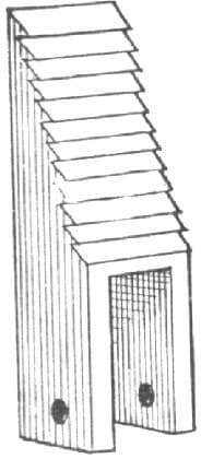
Fig. 171—Showing how the Teeth are made
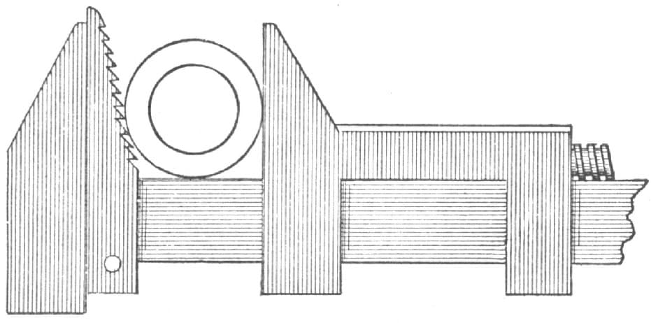
Fig. 172—Showing the Attachment in operation on the Wrench
A Handy Tool for Finishing Seat Rails, etc.
Fig. 173 represents a tool that I have found very handy in finishing eyes in seat rails, braces and other work that requires to be fitted exactly. I made this tool like a number of others that I use, for a particular job. It answered the purpose so well that I made others, of different sizes. It can be made by any machinist. The shank, B, is 21/2 inches long and 1/2 inch in diameter to fit the drilling machine. The head, A, and the follower, C, can be made to agree with the work they are to be used on. The cutting lips, D, are filed to shape, and tempered to straw color. With this tool you can smooth up.—By “BLACKSMITH.”
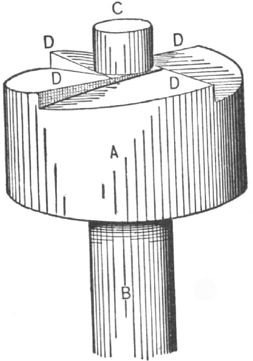
Fig. 173—A Tool for Finishing Eyes in Seat Rails, etc.
A Tool for Pulling Yokes on Clips.
The illustration, Fig. 174, represents a very handy and useful tool of my own invention, which I use for putting yokes on clips or as a clip puller. A and H, as shown in the illustration, are of 3/8 inch square steel, A has two ears welded to it on each side at B, and a loop is welded on at C; F hinges on to H at G, and H hinges on to A at I; E hooks into the yoke; D hooks on the end of the clip. By closing the handles, the yoke is pulled to the clip or vise.—By A. D. S.

Fig. 174—A Tool to Pull Yokes on Clips
Making a Candle Holder.
I was driving, and full thirty miles from a railroad and three miles from the town I wished to reach, when I lost a jack bolt. Fortunately a little smithy was near, but it was late in the day, and before the son of Vulcan had finished his evening meal and was ready to attend to my wants it was dark. With tallow candle in hand, the smith, with his man and I, went to his shop and the job was done; the smith doing the work, the helper holding the candle. I asked the smith if he found it profitable to pay a helper to hold the candle, and he answered that he knew no better way. I told him that I would pass by his shop again the next day and would show him then how to make a cheap and handy candle-holder. I kept my word and did the job before his eyes, as follows:
I took a piece of band iron, 11/4 inches wide and 10 inches long, bent it as shown in the accompanying illustration, so as to join the two angles, each 3 inches long, leaving the back, A, 4 inches. I then bored the holes B B, 1/2 inch, and at L (on A) made a 3/8-inch hole. I next took iron 3/4 × 3/16-inch and 6 inches long, turned a shoulder on it after upsetting, squared the hole at L and fitted into it the end on E. I next took a piece of 1 × 12 inch hoop iron and made the spring D, concaving the ends, which I riveted on the inner side of A by means of the shoulder on E. I next made the pieces F F and G, and drilled and riveted them as at K K K. I next took a block of wood, H, 11/2 inches diameter, 3 inches long, in which I bored a hole to suit the candle, which I secured with a screw on the under side, and my candlestick was complete, as seen in accompanying illustration, Fig. 175.
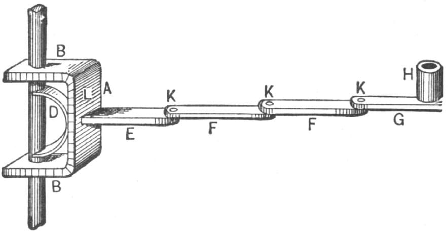
Fig. 175—Showing Candle Holder Complete
My friend watched me patiently all the way through, and was inclined to believe that he had me at my wits’ end and suggested that he was no better off than before. I asked him to have a little patience. I soon found a piece of 7/16 round iron, turned an eye on one end, and, making a point on the other, passed it through the bracket. This served as a support. The spring took good hold. I put the stake in the bench, lowered and raised the holder and turned it every way.—By IRON DOCTOR.
Making a Bolt Trimmer.
I have a bolt trimmer which is very easily made, and cannot help giving satisfaction.
It is shown complete below. The cutting jaws are of good tool steel. The stationary jaw is welded to the iron handle at A, making the handle and cutter one piece. The movable cutter works in a fork, as seen in Fig. 176.
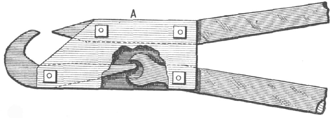
Fig. 176—Showing “C. C. O.’s” Bolt Trimmer Complete
I have my cutter made with side plates, 3 × 7 inches, and handles two feet long.
For convenience in sharpening I have put it together with bolts.—By C. C. O.
A Labor-Saving Tool.
I send drawing of a tool that I have found to be very handy. It is my own idea and a handy tool, especially in plow or buggy work. For plow work it cannot be beaten. The holder is of cast steel and made with two spurs to fit against bolt heads. The steel is welded into a 3/4-round iron, 18 inches long. Drill four or five holes for the pin that runs through the holder.

Fig. 177—Showing “B. F. C.’s” Labor-Saving Tool
To make the holder take two pieces of 11/4 by 5/16 flat iron, weld to make as shown in Fig. 177. Round the end and cut threads for burr brake or pin to hold. When in use the other end is made to pull the bolts to the jaw.
It will be seen from Fig. 177 that this holder is made to turn in any direction and will hold on any shear.—By B. F. C.
Making a Spike-Bar.
I will try to describe a handy spike-bar and tie-fork for mine road men. This tool enables them to do a third more work than they could do with the spike-bar generally used in coal mines. In making the bar I weld 1-inch square steel to 1-inch round iron and use 7/8-round for the fork-prongs. A, in the accompanying illustration, Fig. 178, represents the part that goes under the tie, and B is where the tool rests on the rail. The man, while driving, sits at C. D should be made 1/2 inch longer on the under side than the spike is.—By R. DELBRIDGE.
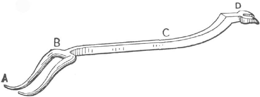
Fig. 178—Handy Spike-bar and Tie-Fork for Mine Road Men
How to Make a Tony Square.
This is a very simple thing to make, and very useful for trying six or eight-square timber or iron. It is very handy in making wheelbarrow hubs or anything of that sort.
Take an ordinary try square and saw a slit in it opposite the blade; next take a piece of steel plate of the same thickness of the blade and cut it to about one-third of the length of blade in the try square. Insert the short blade in the slit as shown in Fig. 179 and you have a “tony” square that will do its work as nice as you please.—By VILLAGE SMITH.
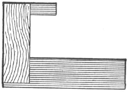
Fig. 179—Showing “Village Smith’s” Tony Square
An Easy Bolt Clipper.
I have a bolt clipper of my own invention and which I think is a very good one. It is simple and easily made The lever E, in Fig. 180, and the jaw I are of one piece of solid steel. The lever L and jaw M are also of steel, but in two pieces, as shown by the dotted line at H, which is a joint that works by the opening and closing of the handle or lever L. F is a steel plate, there being another on the opposite side. The plates are three-sixteenths of an inch thick. The distance from A to B is five inches from center to center of bolt holes. From B to C is two inches from center to center, and from center of bolt hole C to joint H is three and one-half inches. From joint H to center of bolt hole K is one and one-half inches. The handles or levers are two feet six inches in length. The set-screw T is used to prevent the jaws I and M from coming together. With this clipper I can cut anything up to a one-half inch bolt.—By CHRIS. VOGEL.

Fig. 180—An Easy Bolt Clipper, as made by Chris. Vogel
A Tool for Pulling on Felloes.
The illustration, Fig. 181, shows a tool I have for drawing on felloes when making or repairing wheels. The ring, A, which goes over the nut is about 10 inches in diameter; the rod, B, is 2 feet long and made from 5/8 iron. It has a thread cut one-half the length. C is a comet nut about one foot long before being bent. D is a piece of 11/2 × 3/8 inch flat iron and bent as shown. It is drilled 11/16 so that it will easily slip over the rod; the end is widened and slightly turned up. There is power enough in this to draw a small wheel all out of shape.—By LOUIS TUTHILL.
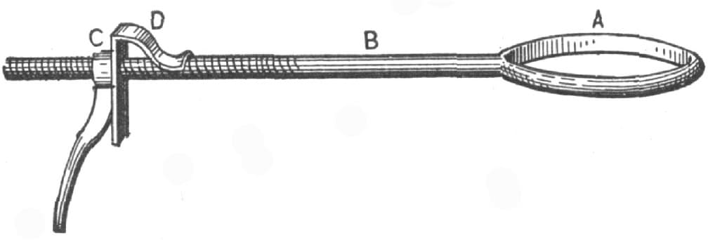
Fig. 181—Tool for Pulling on Felloes, made by Louis Tuthill
How to Make a Handy Hardy.
I have a very handy hardy which can be made with little expense. Take an old saw file and break off a short piece from each end. Draw the temper and it is ready for use. If it should stick to the iron when cutting, grind the sides a little. If you are careful to lay it level on the anvil you will have no difficulty in cutting heavy tires—by turning the iron. I have used one of these hardies for a year without breaking it.—By R. C.
A Handy Clincher.
The accompanying illustration, Fig. 182, represents a clincher which I believe to be a little better than any I have ever seen. It can be made from an old shoeing hammer. The cut shows the construction so clearly that no further explanation is necessary.—By A. F. REINBECK.

Fig. 182—The Handy Clincher, as made by A. F. Reinbeck
A Bolt Holder.
I have a bolt-holder that gives good satisfaction, see Fig. 183: it is very useful in preventing bolts from turning. The eye is forged from 7/8 square iron, the eye 5/16 × 11/2 inches; the part that presses against the bolt-head is steel, the iron being split and spiral inserted; the square part being 5 inches long; from the square to the point, about 41/4 inches; the handle welded out of 3/4-inch round iron. The curved piece passing through eye is made from 1 × 1/4-inch stake iron—By J. F. SMALL.

Fig. 183—Bolt Holder
Making a Cant-Hook.
Some smiths may think that the making of a cant-hook is a job too simple to write about, but to make a hook that will catch hold every time is not so easy after all. My way of making such a hook is as follows:
First, make an eye to go around the handle, then make the hook almost any shape, or bend it so that you can then rivet it to the eye and put on the handle. Bend the point so that it will lie flat on the handle when closed, as shown in the accompanying illustration, Fig. 184. Then it will always catch and hold.—By E. P. A.

Fig. 184—Cant-Hook
Making a Cant-Hook.
The accompanying illustrations represent my way of making a cant-hook.
The clasp is made of 13/4 inch by 1/2-inch Norway iron. I get the exact measure around the handle, and if it be 9 inches around, I measure 41/2 inches on the Norway bar (which is of the right length to handle conveniently), then I take a heat, and with a fuller let in about 7/8 inch to 1 inch from each end. I next draw down the center to nearly the right thickness, bend the ends nearly to a square angle, and set down with the hammer, and make the ends or corners square. I then take a chisel and cut in about 11/8 inch or 1 inch from one edge, for the jaw, leaving this for the thickest part of the clasp. I then set the remainder down with the set-hammer. When both ends are down, I draw to the right length, turn and bend to fit the handle.
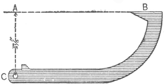
Fig. 185—Making a Cant-Hook. Showing Method of making Shoulder
For the hook, I use 7/8-inch by 1/2-inch steel, 14 inches long. At the end where the hole is, I upset to make a shoulder, as shown in Fig. 185 of the illustrations, which prevents the hook from cutting away the soft iron of the clasp, and prevents the point of the hook from striking the pick.
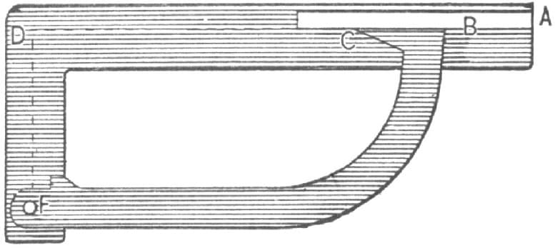
Fig. 186—Showing Method of Setting the Draw
I give 47/8 inches draw as shown by the dotted lines A C, Fig. 185, and to get this exactly every time, I make the tool shown in Fig. 186. In making it I take a bar, 1 foot 6 inches long, 13/4 inches by 1/2-inch, and bend it 13 inches from A to D. At B, Fig. 186, I weld on a piece of iron, 6 inches long by 1/2-inch, with the edge to the D bar, and previously bent to the right shape. I then make the piece B, Fig. 186, true on the face (along C) with the square D. I next measure off from D 47/8 inches to F, and here set a 7/16-inch pin. I make the hook bend and lay as shown in the illustration, Fig. 186, being careful to have the hook true at B D. I file to a point from the inside of the point. For the bands, the first is of 1-inch band iron, the two next are of 11/2 inch, and the toe bands are of 2-inch band iron. This pick is of 7/8-inch square steel, 10 inches long.—By W. W. S.

Fig. 187—Screw Box
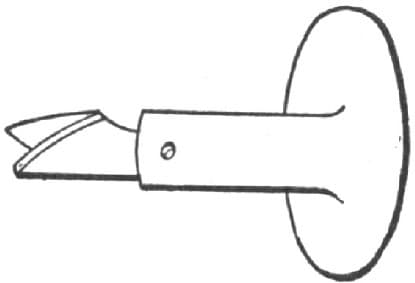
Fig. 188—The Knife
Making Screw Boxes for Cutting Out Wooden Screws.
To make wooden screws by my plan, first take a square piece of steel and with a three-cornered file make the thread on all four corners of the steel for about two inches. When this is done you will have a tap as seen in Fig. 187. To make the screw box as shown in Fig. 188, turn a piece of word (apple wood is the best), with two handles, and bore a hole in the center to the size of the tap with the thread off. Then cut a thread in it with the tap and cut away the wood at one side to admit the knife. This is made as in Fig. 189 with two screws in it, one in the center and the other set. Put the knife in the box so it will match the thread, and screw in over it a piece of wood one-quarter of an inch thick with a hole in it the size of the tap with the thread on, as represented in Fig. 190. The box is then complete—By H. A. S.

Fig. 189—The Tap
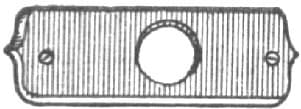
Fig. 190—Piece of Wood used to Secure the Knife in its Place and Admit the Tap
Mending a Square.
In this communication I will tell your readers how to mend a square. Very often a good steel square is rendered useless by having the foot or short end broken off, as in Fig. 191 of the accompanying illustrations. I then work a piece of good iron into the shape shown at A, in Fig. 191, and taking a hack saw, I cut a notch in each piece in which the piece A will fit tightly. I have a square at hand to ensure accuracy, and then having my coal well charred, I take good clean brass and lay it on. When it begins to get hot I put on borax powdered fine—I can’t braze much without borax. When the brass is all melted it is removed from the fire, allowed to cool, and when it is cool the surplus brass and iron are ground off, and the square will then be as good as ever.
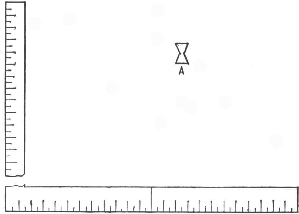
Fig. 191—Showing the Square and the Piece used in Mending
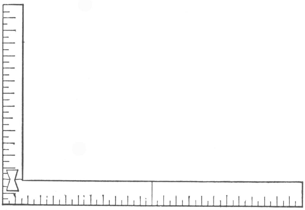
Fig. 192—Showing the Square as Mended
Copper is about as good as brass to braze with. Fig. 192 shows the square when finished.—By J. W. J.
Stand for Carriage Bolts.
From an old buggy shaft, three cheese boxes and four strips of wood I made a very handy stand for carriage and tire bolts, the general appearance of which is afforded by the inclosed sketch, Fig. 193. In the center of each box I nailed a square block. I put partitions on two sides, and also two partitions crossways, in order to make six different sized boxes for different sized bolts. I bored a hole through the center and slipped the box down over the shaft. I fastened it both above and below by nails through the shaft. On the outside surface of the boxes I fastened four strips, using ordinary felloe strips for the purpose, placing them equidistant. Their purpose was to keep the boxes steady. Below and on top I fastened two blocks with holes (bushed) in which the pointed ends of the shaft turn. The device stands in the corner of the shop and is very handy, inasmuch as it easily turns round. Each compartment in the box is marked on the outside in plain figures, thus indicating the size of bolt that it contains.—By F. D. F.

Fig. 193—Stand for Carriage Bolts
An Improved Crane and Swage Block.
In the line of cranes I have something differing from the usual style. It is new, I think, and certainly very good. The engraving, Fig. 194, will explain it. It can be attached to a post in the most convenient position. Mine is hung in thimbles built in the front of the forge chimney. Next in order shall be the swage block. Of all the much abused tools in a smith’s shop, I think the greatest quantity of curses have been bestowed on that patient and unoffending tool. I have known the English language riddled, picked and culled for epithets with the strongest adjectives to hurl at this useful tool. You can hear some of them any time by walking across the shop and stubbing your toe against it as it lays on the floor, and you need not be afraid of hurting it (the swage block I mean). Now, as I consigned mine to the scrap heap many years ago, I will describe a substitute. Get a cast-iron cone mandril, 7 inch diameter at the top and 10 inch at the bottom, with an outside flange at the bottom to form a base, and a strong inside one at the top, having a 4-inch hole in the top, into which cast or wrought-iron collets and swages can be fitted for every kind of work, including farmers’ and other tools. The cone can be made the height of the anvil and forge, so as to be right for the crane to swing to as easy as the anvil.—By IRON JACK.
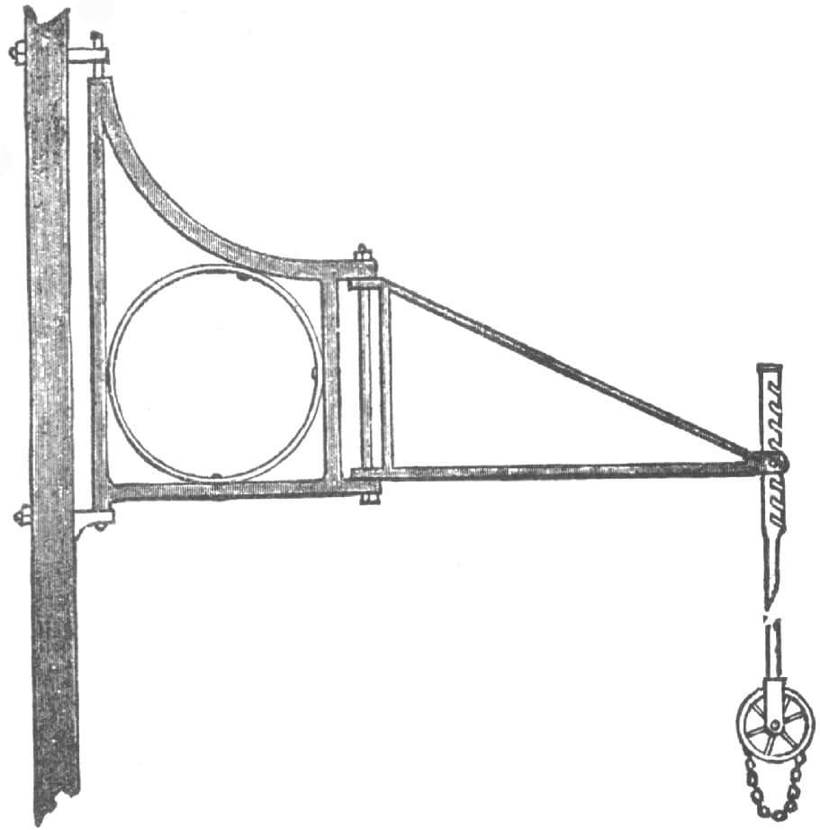
Fig. 194—Improved Crane
A Cheap Crane for Blacksmiths.
The accompanying sketch, Fig. 195, of a cheap crane for blacksmiths needs but little explanation, for any practical man will understand it at a glance. E is a round pole with a band on each end and a gudgeon and mortise to receive the bar C, which is 30 inches × 3/4 inch. At A A make holes and put in rough pins. Then a part, B, is 3/4-round iron, with nuts at the top and joint at the bottom. F is a small sheave, with chain to hold your work, and as you turn your work in the fire or on the anvil it revolves. I am using one of these cranes, and have had eight hundred pounds on it. In every case it answers well. —By SOUTHERN BLACKSMITH.
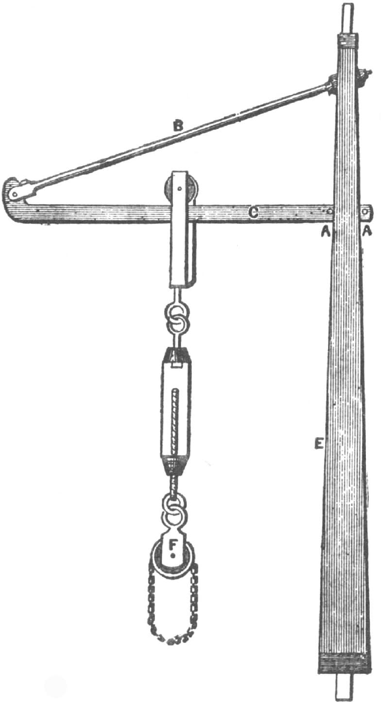
Fig. 195—Cheap Crane
Repairing an Auger.
I will tell your readers my way of putting a screw in an auger. I take the old auger and file a notch in it where the old screw was broken off. I do this work with the edge of the file, making the notch no wider than the old screw was. I then take a 3-square taper file and file the notch wider until it appears as at A in the accompanying illustration, Fig. 196. I next take a small piece of steel, forge out the size desired for the screw, file the piece “dovetailing,” as shown at B, and then slip it sidewise into the auger. It is put in so it can be driven rather snug. When it is fitted it must be brazed.
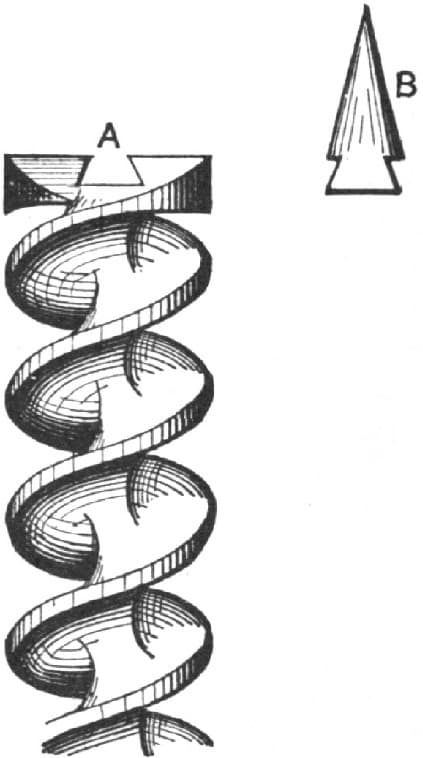
Fig. 196—Repairing an Auger. Showing Notch and Piece to be Fitted into it
Then, commencing inside next to the lip, I file with a 3-square file, and boring the thread half way around, I then commence at the other lip and file a double thread, keeping the two threads side by side and even with each other, by fitting first one a little and then the other about as much, and so on. By this means they can be kept true. An auger repaired in this way is just as good as new. It does not pay to mend small ones in this way, but it is a good plan for large augers, for the operation is simple and requires but a short time.—By ERNEST.
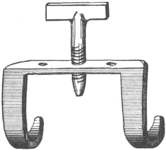
Fig. 197—A Clamp for Holding Countersunk Bolts
A Clamp for Holding Countersunk Boltheads.
I enclose an illustration, Fig. 197, of a clamp that I use in holding countersunk boltheads, while removing the taps from the bolts on spring wagon and buggy felloes. There is no patent on it and it is quickly put on and taken off. It is made of 7/16 inch horseshoe bar with three holes, and has a T headed bolt with threads to tighten. The points hook over the felloe and the point of the bolt, which should be tapering at the point, so it will tighten against the bolt without coming in contact with the tire. I have seen different devices for the purpose but like this the best. It should be made from four to five inches long. It will answer the same purpose for a large wheel by making it larger and stronger.—By W. E. S.
A Handy Machine for a Blacksmith.
A useful machine for any blacksmith is made as follows: Take a piece of lumber 11/2 × 8 and 6 feet long, cut a hole in the middle 2 feet from the end, the dimensions of the hole being 2 × 14, take two cog wheels from some old fan mill, bolt journal boxes for the crank wheel down to the bench on each side of the slot and make an emery wheel mandrel for the small wheel to work on. The mandrel should be of 3/4-inch iron 12 inches long. Plug up the hole in the small wheel and bore a hole for the mandrel, having the mandrel square to avoid turning in the wheel, then weld on a collar. If you have no lathe you can true it up with the hammer and file. Next cut a good screw on the end and put your collar on the end, which should be about 2 inches, and put on a small emery wheel 3/4 inch thick and 8 or 10 inches in diameter. But first put on a washer of thick leather, also another one against the wheel, screw the tap up tight and if it does not turn true you can trim your leather washer down on one edge and by this means get it perfectly true. On the other end of the bench you can attach a good pair of hand shears. For sharpening drills, cold chisels, and a variety of other work, this machine has no equal.—By J. M. WRIGHT.
A Clamp for Framework.
The accompanying illustration, Fig. 198, represents a hand clamp for drawing together framework, such as wagon beds, wheelbarrows, etc.
It is made as follows:
The bar A is of narrow tooth steel which will not bend so easily as iron. It should be five feet long by 1 × 1/2 inch. B is a piece of iron which should be 3 inches high by 11/2 wide, welded to the end and with a 3/4-inch hole having good threads in it. C is a screw to fit the same. It is made one foot long with a crank E which is attached to the end. D is a slide to fit over A, and it should have 3 inches above it a hole 1/4 inch deep to allow the screw C to get a good bearing. F is made the same as D, except that it has a shoulder back of it to keep it from leaning too far back, and a set screw G, at the side, to hold it stationary. I use this clamp almost every day, and I never saw or heard of one just like it.—By V. D. B.

Fig. 198—A Clamp for Framework
A Tool for Holding Bolts.
I send a sketch, Fig. 199, of a tool for holding loose bolts while screwing nuts off. To make it, take a piece of 5/8-inch round iron of suitable length, draw down oval and tapering about 5 inches, and about 7 inches from the pointed end drive in a piece of steel, wedge-shaped, weld securely and sharpen like a chisel; one inch is long enough for this. Then five inches from the end turn it down at right angles, edgewise, and then curl to the left as shown in the illustration. This is better than all the patented tools for this purpose.—By EDWIN CLIFTON.
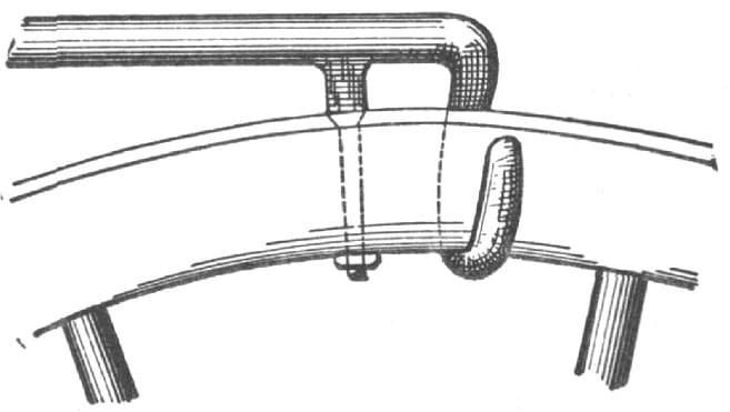
Fig. 199—A Tool for Holding Loose Bolts
A Hint About Callipers.
Let me give some of your young readers a hint how to chamfer off the ends of their callipers from the outside and slightly round them across as in Fig. 200, and not make them rounding as in Fig. 201. The outer points will always touch at the same point no matter what the diameter of the work. If rounding they will touch, for small work, at A, A, and for large work at B, B.—By SHAFTING.
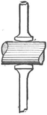
Fig. 200—Right way to Shape Calliper Ends
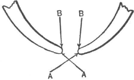
Fig. 201—Wrong way to Shape Calliper Ends
Vise Attachment.
I inclose a paper model of a device that I am using for holding beveled edge iron for filing. It is also useful for chamfering flat iron. In use it is to be screwed in a large vise. The spring shown in the cut, Fig. 202, throws the jaws apart when the vise is released. I think many of your readers will find this idea useful, and as it is one that every blacksmith can put into practical operation, I commend it to the attention of my fellow craftsmen.—By E. M. B.
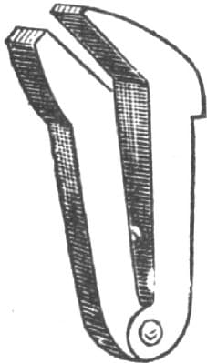
Fig. 202—Vise Attachment
NOTE.—The accompanying engraving has been made from the paper model inclosed in our correspondent’s letter, and, we believe, correctly represents his idea. As he did not show how the spring was attached, or in what form it was to be made, we have nothing to govern us in this particular.—ED.
Bolt Set
We have been using a tool in this community for a long time, which can be applied to wheels very quickly. Any blacksmith who can make a pair of tongs can produce it. It is made of good steel, A in the engraving being chisel-pointed and hardened, so that it can be set into the head of bolt, when it is necessary, by a slight rap with the hammer.—By W. H. S.

Fig. 203—Bolt Set
A Home-Made Lathe.
The accompanying drawings represent a turning lathe that I have been using for some time and find very convenient, not only in turning, but also in drilling small holes. Fig. 204 is a side view of the head stock, and Figs. 205 and 206 show the front and back ends of Fig. 204. In beginning to make the lathe, I take a piece of flat iron 12 inches long, 3 inches wide and 1/4 inch thick, and cut 3 inches at each end, tapering down to 13/4 inches, as shown at a, Fig. 206. I then turn 3 inches of the same ends up at right angles, as at a, Fig. 204, and drill two 3/8-inch holes at b to bolt the head stock. The head stock is braced at c to prevent the springing of the back end of the frame, as all the end pressure comes on that end. I next drill a 3/4-inch hole through the back end and 21/2 inches from the bottom, a, as shown in Fig. 206 at b, and fit to b a piece of round iron 11/2 inches long, with one end countersunk as in Fig. 207 at a. This is to fit the spindle and take up the wear. To prevent this piece from coming out, I double a piece over the end at a, Fig. 205. This piece is 13/4 by 11/4 inches, with a 3/4-inch hole, as shown at a, Fig. 208. It has a 1/4-inch set screw at b.
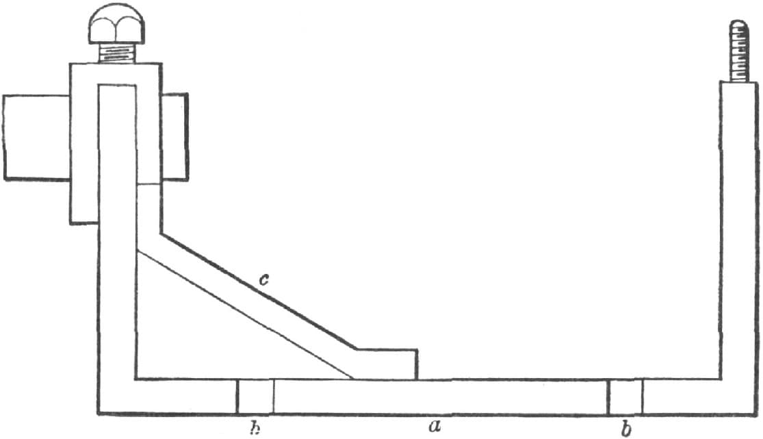
Fig. 204—Side View of the Head Stock
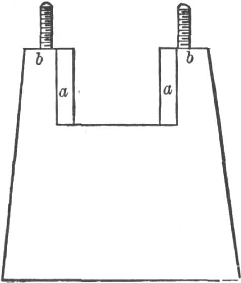
Fig. 205—Front End of the Head Stock
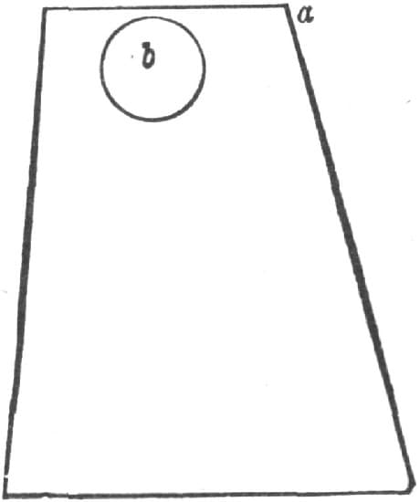
Fig. 206—Back End of the Headstock

Fig. 207—Showing the Piece to be Attached to the Spindle
This piece goes over the end a, Fig. 206, and the piece shown in Fig. 207 goes through the 3/4-inch hole, and the set screw bears on the head stock. By turning up the set-screw the piece, Fig. 207, can be clamped at any place desired, thus forming the bearing for that end. The front end has a place cut out at the center, 11/2 by 1 inch, to receive the boxes. The edges at a, Fig. 205, are beveled to a V, so the two boxes will slide down and fit tightly. The boxes are 11/2 × 13/4 × 3/4 inch. With the ends cut out to fit the V shown in Fig. 205 at a, I next drill in each prong at b, cut a thread and fit a bolt to clamp the boxes. C, in Fig. 209, is the plate that goes over the boxes. The bolts go through the plate into b, Fig. 205. I put the boxes in, placing a thin piece of pasteboard between them, and then clamp them tightly and drill a 3/4-inch hole through them at C. Composition is the best material for the boxes.
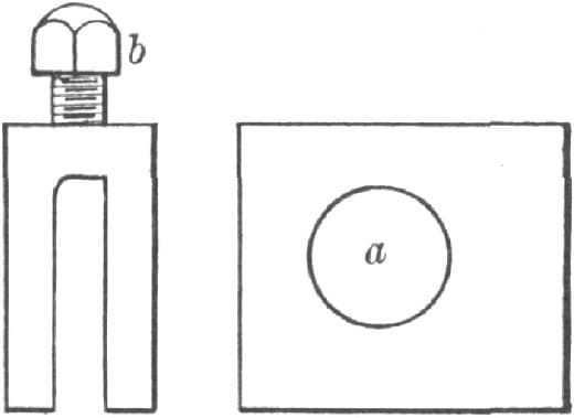
Fig. 208—Showing the Piece used to Secure in Position the Part Shown in Fig. 207
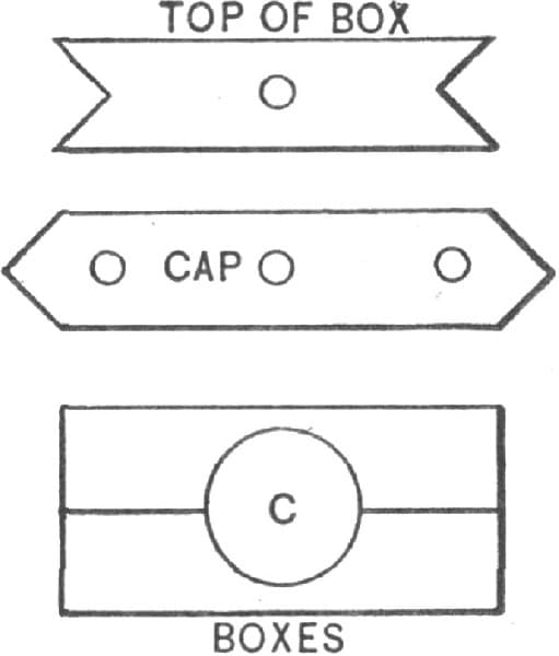
Fig. 209—Showing the Boxes and Plate
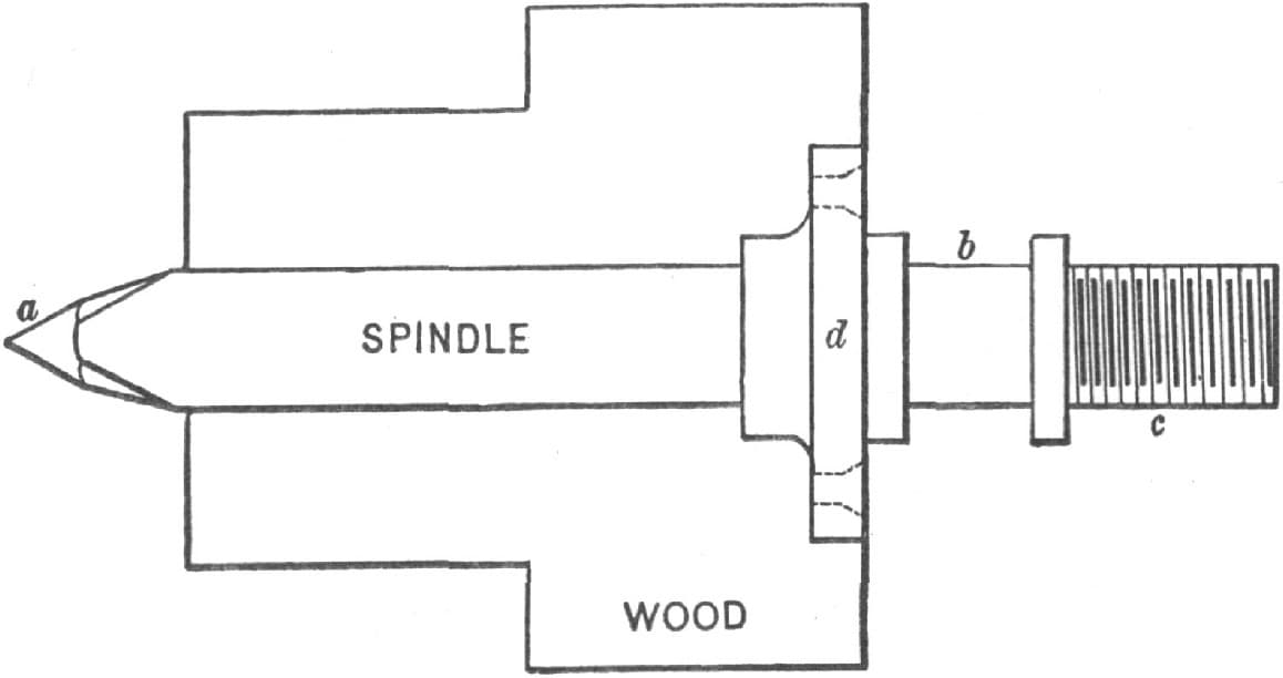
Fig. 210—The Spindle
The spindle must be turned, for it could not be filed true enough to run well. Fig. 210 represents the shape. The end a should fit into Fig. 207 at a. The bearing at the other end is at b, 3/4 inch in diameter. C is turned down a little smaller, and a thread cut on it so as to screw on the face plate. The spur center goes into the spindle with a taper. You can shrink a flange on the spindle at d, and bolt the pulley to that. The face plate needs no description. A glance at Fig. 211 will give anyone a clear idea of it. It might be 5 inches in diameter, and it would answer well enough if it were 3 inches only. The tail stock is of the same dimensions of the head stock, that is, 3 inches wide, 6 inches long, and 3 inches high. Fig. 212 is a side view of the tail stock; Figs. 213 and 214, end views; in Fig. 215 is shown a piece 11/2 inches by 9 inches by 1/4 inch thick, with 11/2 inches of both ends turned at right angles to a. This goes over the ends of Fig. 212 at A.
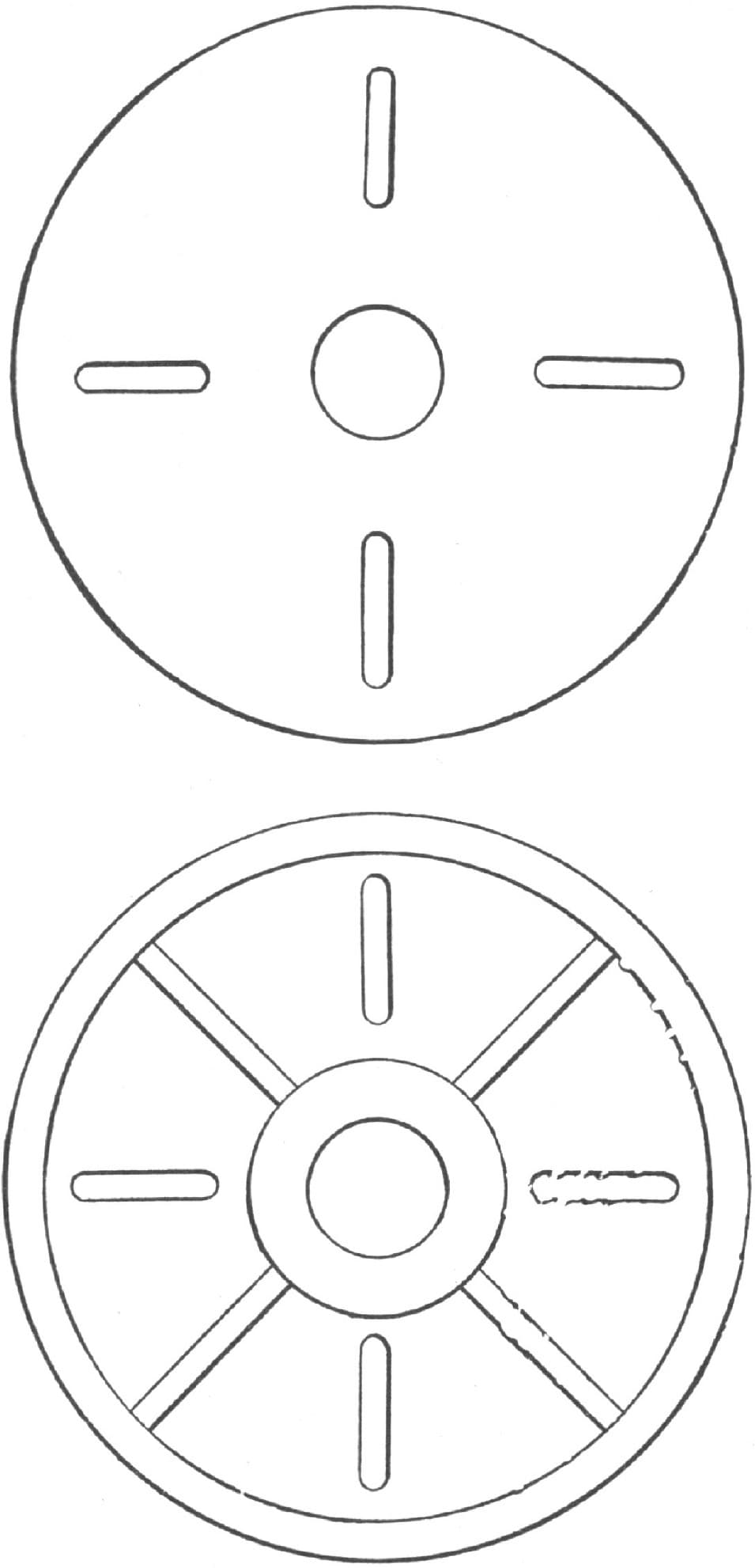
Fig. 211—The Face Plate
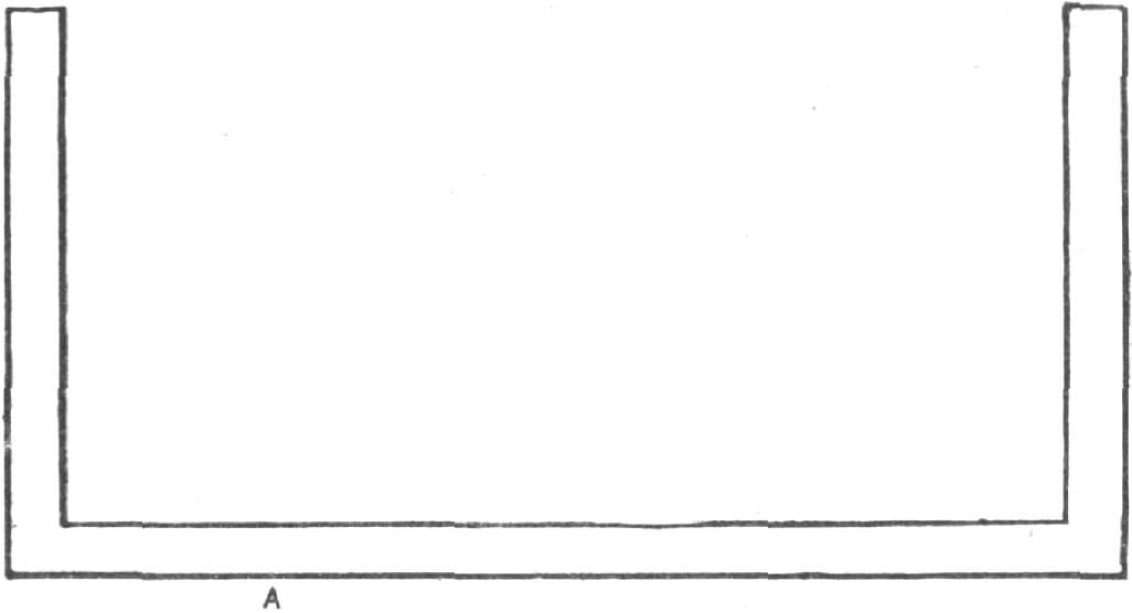
Fig. 212—Side View of the Tail Stock
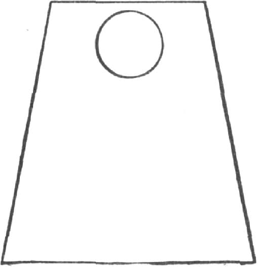
Fig. 213—End View of the Tail Stock
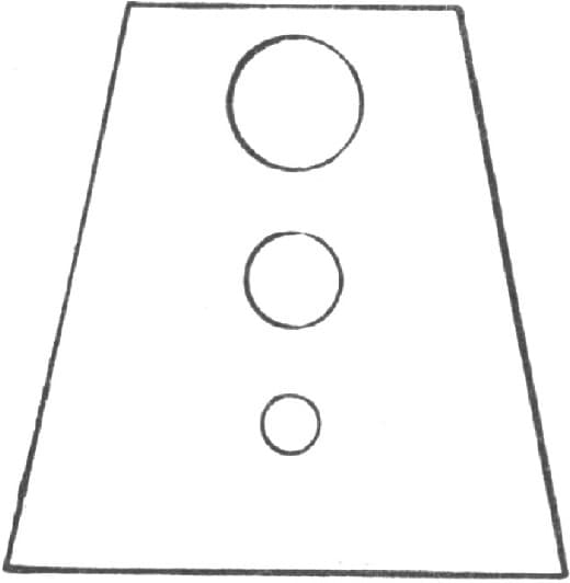
Fig. 214—Back End of the Tail Stock
To clamp the arbor, drill a 3/4-inch hole in both ends of Figs. 213 and 214, 31/2 inches in front of a, and going also through the ends of the piece shown in Fig. 216 at b. This hole must match the holes in Figs. 213 and 114. The purpose of the arrangement is to hold the arbor and keep the work from coming out of the lathe. The set-screw shown in Fig. 215 bears on A, Fig. 212. When the screw is turned, it will keep the arbor from slipping. Fig. 214 has a 1/2-inch hole with a thread cut in it. There must be another hole 1/4 inch in diameter, as shown in the engraving. The arbor is 9 inches long, 3/4 inch in diameter, with one-fourth of one end turned down to 1/2 inch diameter, as shown in Fig. 219. The center goes in the end with a taper as shown in Fig. 217. The center has a place left square to receive a wrench in order to take it out of the arbor. Fig. 218 is a piece 23/4 × 11/4 inches with three holes in it, one 1/2 inch, one 3/8 inch, and the other 1/4 inch. These holes should correspond with the three holes in Fig. 214. Fig. 218 is riveted to the arbor, which is worked with a screw. The guide-pin is fastened to the plate and goes through the smallest hole in the piece Fig. 214. Fig. 220 is a hand wheel which fits on to a very tight nut. To fasten it, there must be work in the plate, so that the screw can be turned in and out. In turning the screw so, you carry the arbor with it. The rest is a flat piece of iron 1/4 inch thick, 8 inches long and 3 inches wide, with 2 inches of one end bent at right angles. There must be two holes near the end, so a piece of wood can be bolted on for turning different lengths. To fasten the rest to the bed cut a hole the size of the bolt, 4 inches long, in the bottom of the rest to let it slide to and from the work.—By H. A. SEAVEY.

Fig. 215—The Piece Used Over the Ends of the Part Shown in Fig. 212
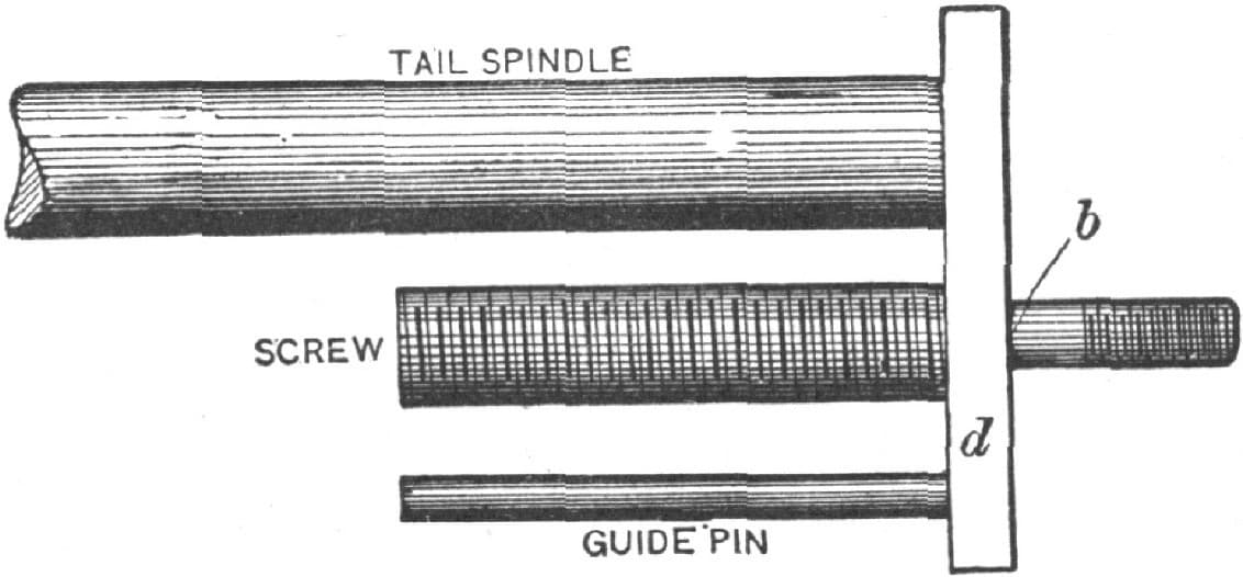
Fig. 216—Showing the Tail Spindle, Screw and Guide Pin

Fig. 217—Showing the Center
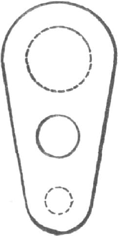
Fig. 218—Showing the Piece Riveted to the Arbor

Fig. 219—The Tail Spindle
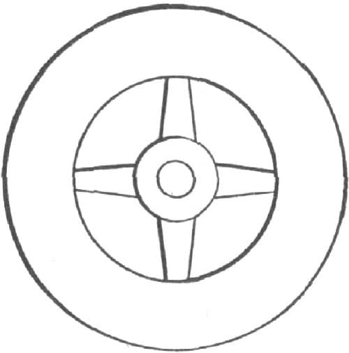
Fig. 220—The Hand Wheel