§29.1194 Other surfaces.
All surfaces aft of, and near, engine compartments and designated fire zones, other than tail surfaces not subject to heat, flames, or sparks emanating from a designated fire zone or engine compartment, must be at least fire resistant.
[Amdt. 29-3, 33 FR 970, Jan. 26, 1968]
§29.1195 Fire extinguishing systems.
(a) Each turbine engine powered rotorcraft and Category A reciprocating engine powered rotorcraft, and each Category B reciprocating engine powered rotorcraft with engines of more than 1,500 cubic inches must have a fire extinguishing system for the designated fire zones. The fire extinguishing system for a powerplant must be able to simultaneously protect all zones of the powerplant compartment for which protection is provided.
(b) For multiengine powered rotorcraft, the fire extinguishing system, the quantity of extinguishing agent, and the rate of discharge must—
(1) For each auxiliary power unit and combustion equipment, provide at least one adequate discharge; and
(2) For each other designated fire zone, provide two adequate discharges.
(c) For single engine rotorcraft, the quantity of extinguishing agent and the rate of discharge must provide at least one adequate discharge for the engine compartment.
(d) It must be shown by either actual or simulated flight tests that under critical airflow conditions in flight the discharge of the extinguishing agent in each designated fire zone will provide an agent concentration capable of extinguishing fires in that zone and of minimizing the probability of reignition.
(Secs. 313(a), 601, 603, 604, Federal Aviation Act of 1958 (49 U.S.C. 1354(a), 1421, 1423, 1424), sec. 6(c), Dept. of Transportation Act (49 U.S.C. 1655(c)))
[Doc. No. 5084, 29 FR 16150, Dec. 3, 1964, as amended by Amdt. 29-3, 33 FR 970, Jan. 26, 1968; Amdt. 29-13, 42 FR 15047, Mar. 17, 1977; Amdt. 29-17, 43 FR 50602, Oct. 30, 1978]
§29.1197 Fire extinguishing agents.
(a) Fire extinguishing agents must—
(1) Be capable of extinguishing flames emanating from any burning of fluids or other combustible materials in the area protected by the fire extinguishing system; and
(2) Have thermal stability over the temperature range likely to be experienced in the compartment in which they are stored.
(b) If any toxic extinguishing agent is used, it must be shown by test that entry of harmful concentrations of fluid or fluid vapors into any personnel compartment (due to leakage during normal operation of the rotorcraft, or discharge on the ground or in flight) is prevented, even though a defect may exist in the extinguishing system.
(Secs. 313(a), 601, and 603, 72 Stat. 759, 775, 49 U.S.C. 1354(a), 1421, and 1423; sec. 6(c), 49 U.S.C. 1655(c))
[Doc. No. 5084, 29 FR 16150, Dec. 3, 1964, as amended by Amdt. 29-12, 41 FR 55473, Dec. 20, 1976; Amdt. 29-13, 42 FR 15047, Mar. 17, 1977]
§29.1199 Extinguishing agent containers.
(a) Each extinguishing agent container must have a pressure relief to prevent bursting of the container by excessive internal pressures.
(b) The discharge end of each discharge line from a pressure relief connection must be located so that discharge of the fire extinguishing agent would not damage the rotorcraft. The line must also be located or protected to prevent clogging caused by ice or other foreign matter.
(c) There must be a means for each fire extinguishing agent container to indicate that the container has discharged or that the charging pressure is below the established minimum necessary for proper functioning.
(d) The temperature of each container must be maintained, under intended operating conditions, to prevent the pressure in the container from—
(1) Falling below that necessary to provide an adequate rate of discharge; or
(2) Rising high enough to cause premature discharge.
(Secs. 313(a), 601, and 603, 72 Stat. 759, 775, 49 U.S.C. 1354(a), 1421, and 1423; sec. 6(c), 49 U.S.C. 1655 (c))
[Doc. No. 5084, 29 FR 16150, Dec. 3, 1964, as amended by Amdt. 29-13, 42 FR 15047, Mar. 17, 1977]
§29.1201 Fire extinguishing system materials.
(a) No materials in any fire extinguishing system may react chemically with any extinguishing agent so as to create a hazard.
(b) Each system component in an engine compartment must be fireproof.
§29.1203 Fire detector systems.
(a) For each turbine engine powered rotorcraft and Category A reciprocating engine powered rotorcraft, and for each Category B reciprocating engine powered rotorcraft with engines of more than 900 cubic inches displacement, there must be approved, quick-acting fire detectors in designated fire zones and in the combustor, turbine, and tailpipe sections of turbine installations (whether or not such sections are designated fire zones) in numbers and locations ensuring prompt detection of fire in those zones.
(b) Each fire detector must be constructed and installed to withstand any vibration, inertia, and other loads to which it would be subjected in operation.
(c) No fire detector may be affected by any oil, water, other fluids, or fumes that might be present.
(d) There must be means to allow crewmembers to check, in flight, the functioning of each fire detector system electrical circuit.
(e) The writing and other components of each fire detector system in an engine compartment must be at least fire resistant.
(f) No fire detector system component for any fire zone may pass through another fire zone, unless—
(1) It is protected against the possibility of false warnings resulting from fires in zones through which it passes; or
(2) The zones involved are simultaneously protected by the same detector and extinguishing systems.
[Doc. No. 5084, 29 FR 16150, Dec. 3, 1964, as amended by Amdt. 29-3, 33 FR 970, Jan. 26, 1968]
Subpart F—Equipment
GENERAL
§29.1301 Function and installation.
Each item of installed equipment must—
(a) Be of a kind and design appropriate to its intended function;
(b) Be labeled as to its identification, function, or operating limitations, or any applicable combination of these factors;
(c) Be installed according to limitations specified for that equipment; and
(d) Function properly when installed.
§29.1303 Flight and navigation instruments.
The following are required flight and navigational instruments:
(a) An airspeed indicator. For Category A rotorcraft with VNE less than a speed at which unmistakable pilot cues provide overspeed warning, a maximum allowable airspeed indicator must be provided. If maximum allowable airspeed varies with weight, altitude, temperature, or r.p.m., the indicator must show that variation.
(b) A sensitive altimeter.
(c) A magnetic direction indicator.
(d) A clock displaying hours, minutes, and seconds with a sweep-second pointer or digital presentation.
(e) A free-air temperature indicator.
(f) A non-tumbling gyroscopic bank and pitch indicator.
(g) A gyroscopic rate-of-turn indicator combined with an integral slip-skid indicator (turn-and-bank indicator) except that only a slip-skid indicator is required on rotorcraft with a third attitude instrument system that—
(1) Is usable through flight attitudes of ±80 degrees of pitch and ±120 degrees of roll;
(2) Is powered from a source independent of the electrical generating system;
(3) Continues reliable operation for a minimum of 30 minutes after total failure of the electrical generating system;
(4) Operates independently of any other attitude indicating system;
(5) Is operative without selection after total failure of the electrical generating system;
(6) Is located on the instrument panel in a position acceptable to the Administrator that will make it plainly visible to and useable by any pilot at his station; and
(7) Is appropriately lighted during all phases of operation.
(h) A gyroscopic direction indicator.
(i) A rate-of-climb (vertical speed) indicator.
(j) For Category A rotorcraft, a speed warning device when VNE is less than the speed at which unmistakable overspeed warning is provided by other pilot cues. The speed warning device must give effective aural warning (differing distinctively from aural warnings used for other purposes) to the pilots whenever the indicated speed exceeds VNE plus 3 knots and must operate satisfactorily throughout the approved range of altitudes and temperatures.
(Secs. 313(a), 601, 603, 604, and 605 of the Federal Aviation Act of 1958 (49 U.S.C. 1354(a), 1421, 1423, 1424, and 1425); and sec. 6(c), Dept. of Transportation Act (49 U.S.C. 1655(c)))
[Doc. No. 5084, 29 FR 16150, Dec. 3, 1964, as amended by Amdt. 29-12, 41 FR 55474, Dec. 20, 1976; Amdt. 29-14, 42 FR 36972, July 18, 1977; Amdt. 29-24, 49 FR 44438, Nov. 6, 1984; 70 FR 2012, Jan. 12, 2005]
§29.1305 Powerplant instruments.
The following are required powerplant instruments:
(a) For each rotorcraft—
(1) A carburetor air temperature indicator for each reciprocating engine;
(2) A cylinder head temperature indicator for each air-cooled reciprocating engine, and a coolant temperature indicator for each liquid-cooled reciprocating engine;
(3) A fuel quantity indicator for each fuel tank;
(4) A low fuel warning device for each fuel tank which feeds an engine. This device must—
(i) Provide a warning to the crew when approximately 10 minutes of usable fuel remains in the tank; and
(ii) Be independent of the normal fuel quantity indicating system.
(5) A manifold pressure indicator, for each reciprocating engine of the altitude type;
(6) An oil pressure indicator for each pressure-lubricated gearbox.
(7) An oil pressure warning device for each pressure-lubricated gearbox to indicate when the oil pressure falls below a safe value;
(8) An oil quantity indicator for each oil tank and each rotor drive gearbox, if lubricant is self-contained;
(9) An oil temperature indicator for each engine;
(10) An oil temperature warning device to indicate unsafe oil temperatures in each main rotor drive gearbox, including gearboxes necessary for rotor phasing;
(11) A gas temperature indicator for each turbine engine;
(12) A gas producer rotor tachometer for each turbine engine;
(13) A tachometer for each engine that, if combined with the applicable instrument required by paragraph (a)(14) of this section, indicates rotor r.p.m. during autorotation.
(14) At least one tachometer to indicate, as applicable—
(i) The r.p.m. of the single main rotor;
(ii) The common r.p.m. of any main rotors whose speeds cannot vary appreciably with respect to each other; and
(iii) The r.p.m. of each main rotor whose speed can vary appreciably with respect to that of another main rotor;
(15) A free power turbine tachometer for each turbine engine;
(16) A means, for each turbine engine, to indicate power for that engine;
(17) For each turbine engine, an indicator to indicate the functioning of the powerplant ice protection system;
(18) An indicator for the filter required by §29.997 to indicate the occurrence of contamination of the filter to the degree established in compliance with §29.955;
(19) For each turbine engine, a warning means for the oil strainer or filter required by §29.1019, if it has no bypass, to warn the pilot of the occurrence of contamination of the strainer or filter before it reaches the capacity established in accordance with §29.1019(a)(2);
(20) An indicator to indicate the functioning of any selectable or controllable heater used to prevent ice clogging of fuel system components;
(21) An individual fuel pressure indicator for each engine, unless the fuel system which supplies that engine does not employ any pumps, filters, or other components subject to degradation or failure which may adversely affect fuel pressure at the engine;
(22) A means to indicate to the flightcrew the failure of any fuel pump installed to show compliance with §29.955;
(23) Warning or caution devices to signal to the flightcrew when ferromagnetic particles are detected by the chip detector required by §29.1337(e); and
(24) For auxiliary power units, an individual indicator, warning or caution device, or other means to advise the flightcrew that limits are being exceeded, if exceeding these limits can be hazardous, for—
(i) Gas temperature;
(ii) Oil pressure; and
(iii) Rotor speed.
(25) For rotorcraft for which a 30-second/2-minute OEI power rating is requested, a means must be provided to alert the pilot when the engine is at the 30-second and 2-minute OEI power levels, when the event begins, and when the time interval expires.
(26) For each turbine engine utilizing 30-second/2-minute OEI power, a device or system must be provided for use by ground personnel which—
(i) Automatically records each usage and duration of power at the 30-second and 2-minute OEI levels;
(ii) Permits retrieval of the recorded data;
(iii) Can be reset only by ground maintenance personnel; and
(iv) Has a means to verify proper operation of the system or device.
(b) For category A rotorcraft—
(1) An individual oil pressure indicator for each engine, and either an independent warning device for each engine or a master warning device for the engines with means for isolating the individual warning circuit from the master warning device;
(2) An independent fuel pressure warning device for each engine or a master warning device for all engines with provision for isolating the individual warning device from the master warning device; and
(3) Fire warning indicators.
(c) For category B rotorcraft—
(1) An individual oil pressure indicator for each engine; and
(2) Fire warning indicators, when fire detection is required.
[Doc. No. 5084, 29 FR 16150, Dec. 3, 1964, as amended by Amdt. 29-3, 33 FR 970, Jan. 26, 1968; Amdt. 29-10, 39 FR 35463, Oct. 1, 1974; Amdt. 29-26, 53 FR 34219, Sept. 2, 1988; Amdt. 29-34, 59 FR 47768, Sept. 16, 1994; Amdt. 29-40, 61 FR 21908, May 10, 1996; 61 FR 43952, Aug. 27, 1996]
§29.1307 Miscellaneous equipment.
The following is required miscellaneous equipment:
(a) An approved seat for each occupant.
(b) A master switch arrangement for electrical circuits other than ignition.
(c) Hand fire extinguishers.
(d) A windshield wiper or equivalent device for each pilot station.
(e) A two-way radio communication system.
[Amdt. 29-12, 41 FR 55473, Dec. 20, 1976]
§29.1309 Equipment, systems, and installations.
(a) The equipment, systems, and installations whose functioning is required by this subchapter must be designed and installed to ensure that they perform their intended functions under any foreseeable operating condition.
(b) The rotorcraft systems and associated components, considered separately and in relation to other systems, must be designed so that—
(1) For Category B rotorcraft, the equipment, systems, and installations must be designed to prevent hazards to the rotorcraft if they malfunction or fail; or
(2) For Category A rotorcraft—
(i) The occurrence of any failure condition which would prevent the continued safe flight and landing of the rotorcraft is extremely improbable; and
(ii) The occurrence of any other failure conditions which would reduce the capability of the rotorcraft or the ability of the crew to cope with adverse operating conditions is improbable.
(c) Warning information must be provided to alert the crew to unsafe system operating conditions and to enable them to take appropriate corrective action. Systems, controls, and associated monitoring and warning means must be designed to minimize crew errors which could create additional hazards.
(d) Compliance with the requirements of paragraph (b)(2) of this section must be shown by analysis and, where necessary, by appropriate ground, flight, or simulator tests. The analysis must consider—
(1) Possible modes of failure, including malfunctions and damage from external sources;
(2) The probability of multiple failures and undetected failures;
(3) The resulting effects on the rotorcraft and occupants, considering the stage of flight and operating conditions; and
(4) The crew warning cues, corrective action required, and the capability of detecting faults.
(e) For Category A rotorcraft, each installation whose functioning is required by this subchapter and which requires a power supply is an “essential load” on the power supply. The power sources and the system must be able to supply the following power loads in probable operating combinations and for probable durations:
(1) Loads connected to the system with the system functioning normally.
(2) Essential loads, after failure of any one prime mover, power converter, or energy storage device.
(3) Essential loads, after failure of—
(i) Any one engine, on rotorcraft with two engines; and
(ii) Any two engines, on rotorcraft with three or more engines.
(f) In determining compliance with paragraphs (e)(2) and (3) of this section, the power loads may be assumed to be reduced under a monitoring procedure consistent with safety in the kinds of operations authorized. Loads not required for controlled flight need not be considered for the two-engine-inoperative condition on rotorcraft with three or more engines.
(g) In showing compliance with paragraphs (a) and (b) of this section with regard to the electrical system and to equipment design and installation, critical environmental conditions must be considered. For electrical generation, distribution, and utilization equipment required by or used in complying with this subchapter, except equipment covered by Technical Standard Orders containing environmental test procedures, the ability to provide continuous, safe service under foreseeable environmental conditions may be shown by environmental tests, design analysis, or reference to previous comparable service experience on other aircraft.
(Secs. 313(a), 601, 603, 604, and 605 of the Federal Aviation Act of 1958 (49 U.S.C. 1354(a), 1421, 1423, 1424, and 1425); and sec. 6(c), Dept. of Transportation Act (49 U.S.C. 1655(c)))
[Doc. No. 5084, 29 FR 16150, Dec. 3, 1964, as amended by Amdt. 29-14, 42 FR 36972, July 18, 1977; Amdt. 29-24, 49 FR 44438, Nov. 6, 1984; Amdt. 29-40, 61 FR 21908, May 10, 1996; Amdt. 29-53, 76 FR 33136, June 8, 2011]
§29.1316 Electrical and electronic system lightning protection.
(a) Each electrical and electronic system that performs a function, for which failure would prevent the continued safe flight and landing of the rotorcraft, must be designed and installed so that—
(1) The function is not adversely affected during and after the time the rotorcraft is exposed to lightning; and
(2) The system automatically recovers normal operation of that function in a timely manner after the rotorcraft is exposed to lightning.
(b) Each electrical and electronic system that performs a function, for which failure would reduce the capability of the rotorcraft or the ability of the flightcrew to respond to an adverse operating condition, must be designed and installed so that the function recovers normal operation in a timely manner after the rotorcraft is exposed to lightning.
[Doc. No. FAA-2010-0224, Amdt. 29-53, 76 FR 33136, June 8, 2011]
§29.1317 High-intensity Radiated Fields (HIRF) Protection.
(a) Except as provided in paragraph (d) of this section, each electrical and electronic system that performs a function whose failure would prevent the continued safe flight and landing of the rotorcraft must be designed and installed so that—
(1) The function is not adversely affected during and after the time the rotorcraft is exposed to HIRF environment I, as described in appendix E to this part;
(2) The system automatically recovers normal operation of that function, in a timely manner, after the rotorcraft is exposed to HIRF environment I, as described in appendix E to this part, unless this conflicts with other operational or functional requirements of that system;
(3) The system is not adversely affected during and after the time the rotorcraft is exposed to HIRF environment II, as described in appendix E to this part; and
(4) Each function required during operation under visual flight rules is not adversely affected during and after the time the rotorcraft is exposed to HIRF environment III, as described in appendix E to this part.
(b) Each electrical and electronic system that performs a function whose failure would significantly reduce the capability of the rotorcraft or the ability of the flightcrew to respond to an adverse operating condition must be designed and installed so the system is not adversely affected when the equipment providing these functions is exposed to equipment HIRF test level 1 or 2, as described in appendix E to this part.
(c) Each electrical and electronic system that performs such a function whose failure would reduce the capability of the rotorcraft or the ability of the flightcrew to respond to an adverse operating condition must be designed and installed so the system is not adversely affected when the equipment providing these functions is exposed to equipment HIRF test level 3, as described in appendix E to this part.
(d) Before December 1, 2012, an electrical or electronic system that performs a function whose failure would prevent the continued safe flight and landing of a rotorcraft may be designed and installed without meeting the provisions of paragraph (a) provided—
(1) The system has previously been shown to comply with special conditions for HIRF, prescribed under §21.16, issued before December 1, 2007;
(2) The HIRF immunity characteristics of the system have not changed since compliance with the special conditions was demonstrated; and
(3) The data used to demonstrate compliance with the special conditions is provided.
[Doc. No. FAA-2006-23657, 72 FR 44027, Aug. 6, 2007]
INSTRUMENTS: INSTALLATION
§29.1321 Arrangement and visibility.
(a) Each flight, navigation, and powerplant instrument for use by any pilot must be easily visible to him from his station with the minimum practicable deviation from his normal position and line of vision when he is looking forward along the flight path.
(b) Each instrument necessary for safe operation, including the airspeed indicator, gyroscopic direction indicator, gyroscopic bank-and-pitch indicator, slip-skid indicator, altimeter, rate-of-climb indicator, rotor tachometers, and the indicator most representative of engine power, must be grouped and centered as nearly as practicable about the vertical plane of the pilot’s forward vision. In addition, for rotorcraft approved for IFR flight—
(1) The instrument that most effectively indicates attitude must be on the panel in the top center position;
(2) The instrument that most effectively indicates direction of flight must be adjacent to and directly below the attitude instrument;
(3) The instrument that most effectively indicates airspeed must be adjacent to and to the left of the attitude instrument; and
(4) The instrument that most effectively indicates altitude or is most frequently utilized in control of altitude must be adjacent to and to the right of the attitude instrument.
(c) Other required powerplant instruments must be closely grouped on the instrument panel.
(d) Identical powerplant instruments for the engines must be located so as to prevent any confusion as to which engine each instrument relates.
(e) Each powerplant instrument vital to safe operation must be plainly visible to appropriate crewmembers.
(f) Instrument panel vibration may not damage, or impair the readability or accuracy of, any instrument.
(g) If a visual indicator is provided to indicate malfunction of an instrument, it must be effective under all probable cockpit lighting conditions.
(Secs. 313(a), 601, 603, 604, and 605 of the Federal Aviation Act of 1958 (49 U.S.C. 1354(a), 1421, 1423, 1424, and 1425); and sec. 6(c), Dept. of Transportation Act (49 U.S.C. 1655(c)))
[Doc. No. 5084, 29 FR 16150, Dec. 3, 1964, as amended by Amdt. 29-14, 42 FR 36972, July 18, 1977; Amdt. 29-21, 48 FR 4391, Jan. 31, 1983]
§29.1322 Warning, caution, and advisory lights.
If warning, caution or advisory lights are installed in the cockpit they must, unless otherwise approved by the Administrator, be—
(a) Red, for warning lights (lights indicating a hazard which may require immediate corrective action);
(b) Amber, for caution lights (lights indicating the possible need for future corrective action);
(c) Green, for safe operation lights; and
(d) Any other color, including white, for lights not described in paragraphs (a) through (c) of this section, provided the color differs sufficiently from the colors prescribed in paragraphs (a) through (c) of this section to avoid possible confusion.
[Amdt. 29-12, 41 FR 55474, Dec. 20, 1976]
§29.1323 Airspeed indicating system.
For each airspeed indicating system, the following apply:
(a) Each airspeed indicating instrument must be calibrated to indicate true airspeed (at sea level with a standard atmosphere) with a minimum practicable instrument calibration error when the corresponding pitot and static pressures are applied.
(b) Each system must be calibrated to determine system error excluding airspeed instrument error. This calibration must be determined—
(1) In level flight at speeds of 20 knots and greater, and over an appropriate range of speeds for flight conditions of climb and autorotation; and
(2) During takeoff, with repeatable and readable indications that ensure—
(i) Consistent realization of the field lengths specified in the Rotorcraft Flight Manual; and
(ii) Avoidance of the critical areas of the height-velocity envelope as established under §29.87.
(c) For Category A rotorcraft—
(1) The indication must allow consistent definition of the takeoff decision point; and
(2) The system error, excluding the airspeed instrument calibration error, may not exceed—
(i) Three percent or 5 knots, whichever is greater, in level flight at speeds above 80 percent of takeoff safety speed; and
(ii) Ten knots in climb at speeds from 10 knots below takeoff safety speed to 10 knots above VY.
(d) For Category B rotorcraft, the system error, excluding the airspeed instrument calibration error, may not exceed 3 percent or 5 knots, whichever is greater, in level flight at speeds above 80 percent of the climbout speed attained at 50 feet when complying with §29.63.
(e) Each system must be arranged, so far as practicable, to prevent malfunction or serious error due to the entry of moisture, dirt, or other substances.
(f) Each system must have a heated pitot tube or an equivalent means of preventing malfunction due to icing.
[Doc. No. 5084, 29 FR 16150, Dec. 3, 1964, as amended by Amdt. 29-3, 33 FR 970, Jan. 26, 1968; Amdt. 29-24, 49 FR 44439, Nov. 6, 1984; Amdt. 29-39, 61 FR 21901, May 10, 1996; Amdt. 29-44, 64 FR 45338, Aug. 19, 1999]
§29.1325 Static pressure and pressure altimeter systems.
(a) Each instrument with static air case connections must be vented to the outside atmosphere through an appropriate piping system.
(b) Each vent must be located where its orifices are least affected by airflow variation, moisture, or foreign matter.
(c) Each static pressure port must be designed and located in such manner that the correlation between air pressure in the static pressure system and true ambient atmospheric static pressure is not altered when the rotorcraft encounters icing conditions. An anti-icing means or an alternate source of static pressure may be used in showing compliance with this requirement. If the reading of the altimeter, when on the alternate static pressure system, differs from the reading of altimeter when on the primary static system by more than 50 feet, a correction card must be provided for the alternate static system.
(d) Except for the vent into the atmosphere, each system must be airtight.
(e) Each pressure altimeter must be approved and calibrated to indicate pressure altitude in a standard atmosphere with a minimum practicable calibration error when the corresponding static pressures are applied.
(f) Each system must be designed and installed so that an error in indicated pressure altitude, at sea level, with a standard atmosphere, excluding instrument calibration error, does not result in an error of more than ±30 feet per 100 knots speed. However, the error need not be less than ±30 feet.
(g) Except as provided in paragraph (h) of this section, if the static pressure system incorporates both a primary and an alternate static pressure source, the means for selecting one or the other source must be designed so that—
(1) When either source is selected, the other is blocked off; and
(2) Both sources cannot be blocked off simultaneously.
(h) For unpressurized rotorcraft, paragraph (g)(1) of this section does not apply if it can be demonstrated that the static pressure system calibration, when either static pressure source is selected, is not changed by the other static pressure source being open or blocked.
(Secs. 313(a), 601, 603, 604, and 605 of the Federal Aviation Act of 1958 (49 U.S.C. 1354(a), 1421, 1423, 1424, and 1425); and sec. 6(c), Dept. of Transportation Act (49 U.S.C. 1655(c)))
[Doc. No. 5084, 29 FR 16150, Dec. 3, 1964, as amended by Amdt. 29-14, 42 FR 36972, July 18, 1977; Amdt. 29-24, 49 FR 44439, Nov. 6, 1984]
§29.1327 Magnetic direction indicator.
(a) Each magnetic direction indicator must be installed so that its accuracy is not excessively affected by the rotorcraft’s vibration or magnetic fields.
(b) The compensated installation may not have a deviation, in level flight, greater than 10 degrees on any heading.
§29.1329 Automatic pilot system.
(a) Each automatic pilot system must be designed so that the automatic pilot can—
(1) Be sufficiently overpowered by one pilot to allow control of the rotorcraft; and
(2) Be readily and positively disengaged by each pilot to prevent it from interfering with the control of the rotorcraft.
(b) Unless there is automatic synchronization, each system must have a means to readily indicate to the pilot the alignment of the actuating device in relation to the control system it operates.
(c) Each manually operated control for the system’s operation must be readily accessible to the pilots.
(d) The system must be designed and adjusted so that, within the range of adjustment available to the pilot, it cannot produce hazardous loads on the rotorcraft, or create hazardous deviations in the flight path, under any flight condition appropriate to its use, either during normal operation or in the event of a malfunction, assuming that corrective action begins within a reasonable period of time.
(e) If the automatic pilot integrates signals from auxiliary controls or furnishes signals for operation of other equipment, there must be positive interlocks and sequencing of engagement to prevent improper operation.
(f) If the automatic pilot system can be coupled to airborne navigation equipment, means must be provided to indicate to the pilots the current mode of operation. Selector switch position is not acceptable as a means of indication.
[Doc. No. 5084, 29 FR 16150, Dec. 3, 1964, as amended by Amdt. 29-24, 49 FR 44439, Nov. 6, 1984; Amdt. 29-24, 49 FR 47594, Dec. 6, 1984; Amdt. 29-42, 63 FR 43285, Aug. 12, 1998]
§29.1331 Instruments using a power supply.
For category A rotorcraft—
(a) Each required flight instrument using a power supply must have—
(1) Two independent sources of power;
(2) A means of selecting either power source; and
(3) A visual means integral with each instrument to indicate when the power adequate to sustain proper instrument performance is not being supplied. The power must be measured at or near the point where it enters the instrument. For electrical instruments, the power is considered to be adequate when the voltage is within the approved limits; and
(b) The installation and power supply system must be such that failure of any flight instrument connected to one source, or of the energy supply from one source, or a fault in any part of the power distribution system does not interfere with the proper supply of energy from any other source.
[Doc. No. 5084, 29 FR 16150, Dec. 3, 1964, as amended by Amdt. 29-24, 49 FR 44439, Nov. 6, 1984]
§29.1333 Instrument systems.
For systems that operate the required flight instruments which are located at each pilot’s station, the following apply:
(a) Only the required flight instruments for the first pilot may be connected to that operating system.
(b) The equipment, systems, and installations must be designed so that one display of the information essential to the safety of flight which is provided by the flight instruments remains available to a pilot, without additional crewmember action, after any single failure or combination of failures that are not shown to be extremely improbable.
(c) Additional instruments, systems, or equipment may not be connected to the operating system for a second pilot unless provisions are made to ensure the continued normal functioning of the required flight instruments in the event of any malfunction of the additional instruments, systems, or equipment which is not shown to be extremely improbable.
[Amdt. 29-24, 49 FR 44439, Nov. 6, 1984]
§29.1335 Flight director systems.
If a flight director system is installed, means must be provided to indicate to the flight crew its current mode of operation. Selector switch position is not acceptable as a means of indication.
(Secs. 313(a), 601, 603, 604, and 605 of the Federal Aviation Act of 1958 (49 U.S.C. 1354(a), 1421, 1423, 1424, and 1425); and sec. 6(c), Dept. of Transportation Act (49 U.S.C. 1655(c)))
[Amdt. 29-14, 42 FR 36973, July 18, 1977]
§29.1337 Powerplant instruments.
(a) Instruments and instrument lines. (1) Each powerplant and auxiliary power unit instrument line must meet the requirements of §§29.993 and 29.1183.
(2) Each line carrying flammable fluids under pressure must—
(i) Have restricting orifices or other safety devices at the source of pressure to prevent the escape of excessive fluid if the line fails; and
(ii) Be installed and located so that the escape of fluids would not create a hazard.
(3) Each powerplant and auxiliary power unit instrument that utilizes flammable fluids must be installed and located so that the escape of fluid would not create a hazard.
(b) Fuel quantity indicator. There must be means to indicate to the flight crew members the quantity, in gallons or equivalent units, of usable fuel in each tank during flight. In addition—
(1) Each fuel quantity indicator must be calibrated to read “zero” during level flight when the quantity of fuel remaining in the tank is equal to the unusable fuel supply determined under §29.959;
(2) When two or more tanks are closely interconnected by a gravity feed system and vented, and when it is impossible to feed from each tank separately, at least one fuel quantity indicator must be installed;
(3) Tanks with interconnected outlets and airspaces may be treated as one tank and need not have separate indicators; and
(4) Each exposed sight gauge used as a fuel quantity indicator must be protected against damage.
(c) Fuel flowmeter system. If a fuel flowmeter system is installed, each metering component must have a means for bypassing the fuel supply if malfunction of that component severely restricts fuel flow.
(d) Oil quantity indicator. There must be a stick gauge or equivalent means to indicate the quantity of oil—
(1) In each tank; and
(2) In each transmission gearbox.
(e) Rotor drive system transmissions and gearboxes utilizing ferromagnetic materials must be equipped with chip detectors designed to indicate the presence of ferromagnetic particles resulting from damage or excessive wear within the transmission or gearbox. Each chip detector must—
(1) Be designed to provide a signal to the indicator required by §29.1305(a)(22); and
(2) Be provided with a means to allow crewmembers to check, in flight, the function of each detector electrical circuit and signal.
(Secs. 313(a), 601, and 603, 72 Stat. 759, 775, 49 U.S.C. 1354(a), 1421, and 1423; sec. 6(c), 49 U.S.C. 1655(c))
[Doc. No. 5084, 29 FR 16150, Dec. 3, 1964, as amended by Amdt. 29-13, 42 FR 15047, Mar. 17, 1977; Amdt. 29-26, 53 FR 34219, Sept. 2, 1988]
ELECTRICAL SYSTEMS AND EQUIPMENT
§29.1351 General.
(a) Electrical system capacity. The required generating capacity and the number and kind of power sources must—
(1) Be determined by an electrical load analysis; and
(2) Meet the requirements of §29.1309.
(b) Generating system. The generating system includes electrical power sources, main power busses, transmission cables, and associated control, regulation, and protective devices. It must be designed so that—
(1) Power sources function properly when independent and when connected in combination;
(2) No failure or malfunction of any power source can create a hazard or impair the ability of remaining sources to supply essential loads;
(3) The system voltage and frequency (as applicable) at the terminals of essential load equipment can be maintained within the limits for which the equipment is designed, during any probable operating condition;
(4) System transients due to switching, fault clearing, or other causes do not make essential loads inoperative, and do not cause a smoke or fire hazard;
(5) There are means accessible in flight to appropriate crewmembers for the individual and collective disconnection of the electrical power sources from the main bus; and
(6) There are means to indicate to appropriate crewmembers the generating system quantities essential for the safe operation of the system, such as the voltage and current supplied by each generator.
(c) External power. If provisions are made for connecting external power to the rotorcraft, and that external power can be electrically connected to equipment other than that used for engine starting, means must be provided to ensure that no external power supply having a reverse polarity, or a reverse phase sequence, can supply power to the rotorcraft’s electrical system.
(d) Operation with the normal electrical power generating system inoperative.
(1) It must be shown by analysis, tests, or both, that the rotorcraft can be operated safely in VFR conditions for a period of not less than 5 minutes, with the normal electrical power generating system (electrical power sources excluding the battery) inoperative, with critical type fuel (from the standpoint of flameout and restart capability), and with the rotorcraft initially at the maximum certificated altitude. Parts of the electrical system may remain on if—
(i) A single malfunction, including a wire bundle or junction box fire, cannot result in loss of the part turned off and the part turned on;
(ii) The parts turned on are electrically and mechanically isolated from the parts turned off; and
(2) Additional requirements for Category A Rotorcraft.
(i) Unless it can be shown that the loss of the normal electrical power generating system is extremely improbable, an emergency electrical power system, independent of the normal electrical power generating system, must be provided, with sufficient capacity to power all systems necessary for continued safe flight and landing.
(ii) Failures, including junction box, control panel, or wire bundle fires, which would result in the loss of the normal and emergency systems, must be shown to be extremely improbable.
(iii) Systems necessary for immediate safety must continue to operate following the loss of the normal electrical power generating system, without the need for flight crew action.
(Secs. 313(a), 601, 603, 604, and 605 of the Federal Aviation Act of 1958 (49 U.S.C. 1354(a), 1421, 1423, 1424, and 1425); and sec. 6(c), Dept. of Transportation Act (49 U.S.C. 1655(c)))
[Doc. No. 5084, 29 FR 16150, Dec. 3, 1964, as amended by Amdt. 29-14, 42 FR 36973, July 18, 1977; Amdt. 29-40, 61 FR 21908, May 10, 1996; Amdt. 29-42, 63 FR 43285, Aug. 12, 1998]
§29.1353 Electrical equipment and installations.
(a) Electrical equipment, controls, and wiring must be installed so that operation of any one unit or system of units will not adversely affect the simultaneous operation of any other electrical unit or system essential to safe operation.
(b) Cables must be grouped, routed, and spaced so that damage to essential circuits will be minimized if there are faults in heavy current-carrying cables.
(c) Storage batteries must be designed and installed as follows:
(1) Safe cell temperatures and pressures must be maintained during any probable charging and discharging condition. No uncontrolled increase in cell temperature may result when the battery is recharged (after previous complete discharge)—
(i) At maximum regulated voltage or power;
(ii) During a flight of maximum duration; and
(iii) Under the most adverse cooling condition likely in service.
(2) Compliance with paragraph (a)(1) of this section must be shown by test unless experience with similar batteries and installations has shown that maintaining safe cell temperatures and pressures presents no problem.
(3) No explosive or toxic gases emitted by any battery in normal operation, or as the result of any probable malfunction in the charging system or battery installation, may accumulate in hazardous quantities within the rotorcraft.
(4) No corrosive fluids or gases that may escape from the battery may damage surrounding structures or adjacent essential equipment.
(5) Each nickel cadmium battery installation capable of being used to start an engine or auxiliary power unit must have provisions to prevent any hazardous effect on structure or essential systems that may be caused by the maximum amount of heat the battery can generate during a short circuit of the battery or of its individual cells.
(6) Nickel cadmium battery installations capable of being used to start an engine or auxiliary power unit must have—
(i) A system to control the charging rate of the battery automatically so as to prevent battery overheating;
(ii) A battery temperature sensing and over-temperature warning system with a means for disconnecting the battery from its charging source in the event of an over-temperature condition; or
(iii) A battery failure sensing and warning system with a means for disconnecting the battery from its charging source in the event of battery failure.
(Secs. 313(a), 601, 603, 604, and 605 of the Federal Aviation Act of 1958 (49 U.S.C. 1354(a), 1421, 1423, 1424, and 1425); and sec. 6(c), Dept. of Transportation Act (49 U.S.C. 1655(c)))
[Doc. No. 5084, 29 FR 16150, Dec. 3, 1964, as amended by Amdt. 29-14, 42 FR 36973, July 18, 1977; Amdt. 29-15, 43 FR 2327, Jan. 16, 1978]
§29.1355 Distribution system.
(a) The distribution system includes the distribution busses, their associated feeders, and each control and protective device.
(b) If two independent sources of electrical power for particular equipment or systems are required by this chapter, in the event of the failure of one power source for such equipment or system, another power source (including its separate feeder) must be provided automatically or be manually selectable to maintain equipment or system operation.
(Secs. 313(a), 601, 603, 604, and 605 of the Federal Aviation Act of 1958 (49 U.S.C. 1354(a), 1421, 1423, 1424, and 1425); and sec. 6(c), Dept. of Transportation Act (49 U.S.C. 1655(c)))
[Doc. No. 5084, 29 FR 16150, Dec. 3, 1964, as amended by Amdt. 29-14, 42 FR 36973, July 18, 1977; Amdt. 29-24, 49 FR 44439, Nov. 6, 1984]
§29.1357 Circuit protective devices.
(a) Automatic protective devices must be used to minimize distress to the electrical system and hazard to the rotorcraft system and hazard to the rotorcraft in the event of wiring faults or serious malfunction of the system or connected equipment.
(b) The protective and control devices in the generating system must be designed to de-energize and disconnect faulty power sources and power transmission equipment from their associated buses with sufficient rapidity to provide protection from hazardous overvoltage and other malfunctioning.
(c) Each resettable circuit protective device must be designed so that, when an overload or circuit fault exists, it will open the circuit regardless of the position of the operating control.
(d) If the ability to reset a circuit breaker or replace a fuse is essential to safety in flight, that circuit breaker or fuse must be located and identified so that it can be readily reset or replaced in flight.
(e) Each essential load must have individual circuit protection. However, individual protection for each circuit in an essential load system (such as each position light circuit in a system) is not required.
(f) If fuses are used, there must be spare fuses for use in flight equal to at least 50 percent of the number of fuses of each rating required for complete circuit protection.
(g) Automatic reset circuit breakers may be used as integral protectors for electrical equipment provided there is circuit protection for the cable supplying power to the equipment.
[Doc. No. 5084, 29 FR 16150, Dec. 3, 1964, as amended by Amdt. 29-24, 49 FR 44440, Nov. 6, 1984]
§29.1359 Electrical system fire and smoke protection.
(a) Components of the electrical system must meet the applicable fire and smoke protection provisions of §§29.831 and 29.863.
(b) Electrical cables, terminals, and equipment, in designated fire zones, and that are used in emergency procedures, must be at least fire resistant.
(c) Insulation on electrical wire and cable installed in the rotorcraft must be self-extinguishing when tested in accordance with Appendix F, Part I(a)(3), of part 25 of this chapter.
[Doc. No. 5084, 29 FR 16150, Dec. 3, 1964, as amended by Amdt. 29-42, 63 FR 43285, Aug. 12, 1998]
§29.1363 Electrical system tests.
(a) When laboratory tests of the electrical system are conducted—
(1) The tests must be performed on a mock-up using the same generating equipment used in the rotorcraft;
(2) The equipment must simulate the electrical characteristics of the distribution wiring and connected loads to the extent necessary for valid test results; and
(3) Laboratory generator drives must simulate the prime movers on the rotorcraft with respect to their reaction to generator loading, including loading due to faults.
(b) For each flight condition that cannot be simulated adequately in the laboratory or by ground tests on the rotorcraft, flight tests must be made.
LIGHTS
§29.1381 Instrument lights.
The instrument lights must—
(a) Make each instrument, switch, and other device for which they are provided easily readable; and
(b) Be installed so that—
(1) Their direct rays are shielded from the pilot’s eyes; and
(2) No objectionable reflections are visible to the pilot.
§29.1383 Landing lights.
(a) Each required landing or hovering light must be approved.
(b) Each landing light must be installed so that—
(1) No objectionable glare is visible to the pilot;
(2) The pilot is not adversely affected by halation; and
(3) It provides enough light for night operation, including hovering and landing.
(c) At least one separate switch must be provided, as applicable—
(1) For each separately installed landing light; and
(2) For each group of landing lights installed at a common location.
§29.1385 Position light system installation.
(a) General. Each part of each position light system must meet the applicable requirements of this section and each system as a whole must meet the requirements of §§29.1387 through 29.1397.
(b) Forward position lights. Forward position lights must consist of a red and a green light spaced laterally as far apart as practicable and installed forward on the rotorcraft so that, with the rotorcraft in the normal flying position, the red light is on the left side, and the green light is on the right side. Each light must be approved.
(c) Rear position light. The rear position light must be a white light mounted as far aft as practicable, and must be approved.
(d) Circuit. The two forward position lights and the rear position light must make a single circuit.
(e) Light covers and color filters. Each light cover or color filter must be at least flame resistant and may not change color or shape or lose any appreciable light transmission during normal use.
§29.1387 Position light system dihedral angles.
(a) Except as provided in paragraph (e) of this section, each forward and rear position light must, as installed, show unbroken light within the dihedral angles described in this section.
(b) Dihedral angle L (left) is formed by two intersecting vertical planes, the first parallel to the longitudinal axis of the rotorcraft, and the other at 110 degrees to the left of the first, as viewed when looking forward along the longitudinal axis.
(c) Dihedral angle R (right) is formed by two intersecting vertical planes, the first parallel to the longitudinal axis of the rotorcraft, and the other at 110 degrees to the right of the first, as viewed when looking forward along the longitudinal axis.
(d) Dihedral angle A (aft) is formed by two intersecting vertical planes making angles of 70 degrees to the right and to the left, respectively, to a vertical plane passing through the longitudinal axis, as viewed when looking aft along the longitudinal axis.
(e) If the rear position light, when mounted as far aft as practicable in accordance with §29.1385(c), cannot show unbroken light within dihedral angle A (as defined in paragraph (d) of this section), a solid angle or angles of obstructed visibility totaling not more than 0.04 steradians is allowable within that dihedral angle, if such solid angle is within a cone whose apex is at the rear position light and whose elements make an angle of 30° with a vertical line passing through the rear position light.
(49 U.S.C. 1655(c))
[Doc. No. 5084, 29 FR 16150, Dec. 3, 1964, as amended by Amdt. 29-9, 36 FR 21279, Nov. 5, 1971]
§29.1389 Position light distribution and intensities.
(a) General. The intensities prescribed in this section must be provided by new equipment with light covers and color filters in place. Intensities must be determined with the light source operating at a steady value equal to the average luminous output of the source at the normal operating voltage of the rotorcraft. The light distribution and intensity of each position light must meet the requirements of paragraph (b) of this section.
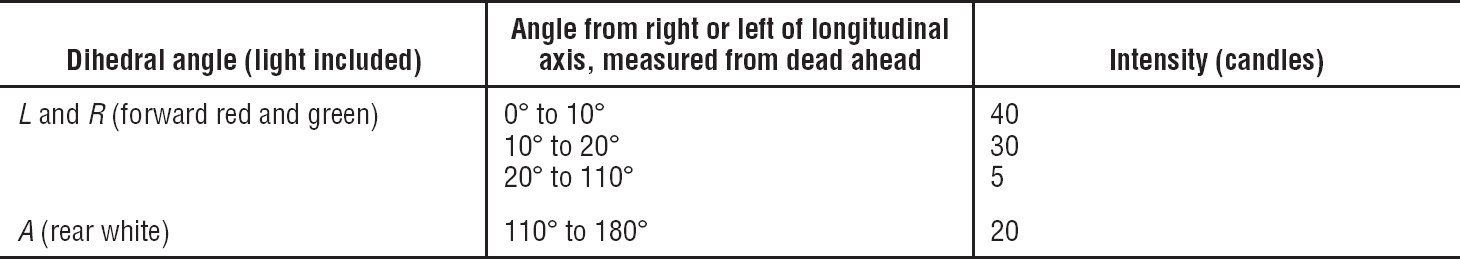
(b) Forward and rear position lights. The light distribution and intensities of forward and rear position lights must be expressed in terms of minimum intensities in the horizontal plane, minimum intensities in any vertical plane, and maximum intensities in overlapping beams, within dihedral angles, L, R, and A, and must meet the following requirements:
(1) Intensities in the horizontal plane. Each intensity in the horizontal plane (the plane containing the longitudinal axis of the rotorcraft and perpendicular to the plane of symmetry of the rotorcraft), must equal or exceed the values in §29.1391.
(2) Intensities in any vertical plane. Each intensity in any vertical plane (the plane perpendicular to the horizontal plane) must equal or exceed the appropriate value in §29.1393 where I is the minimum intensity prescribed in §29.1391 for the corresponding angles in the horizontal plane.
(3) Intensities in overlaps between adjacent signals. No intensity in any overlap between adjacent signals may exceed the values in §29.1395, except that higher intensities in overlaps may be used with the use of main beam intensities substantially greater than the minima specified in §§29.1391 and 29.1393 if the overlap intensities in relation to the main beam intensities do not adversely affect signal clarity.
§29.1391 Minimum intensities in the horizontal plane of forward and rear position lights.
Each position light intensity must equal or exceed the applicable values in the following table:
§29.1393 Minimum intensities in any vertical plane of forward and rear position lights.
Each position light intensity must equal or exceed the applicable values in the following table:
Angle above or below the horizontal plane |
Intensity, I |
0° |
1.00 |
0° to 5° |
.90 |
5° to 10° |
.80 |
10° to 15° |
.70 |
15° to 20° |
.50 |
20° to 30° |
.30 |
30° to 40° |
.10 |
40° to 90° |
.05 |
§29.1395 Maximum intensities in overlapping beams of forward and rear position lights.
No position light intensity may exceed the applicable values in the following table, except as provided in §29.1389(b)(3).
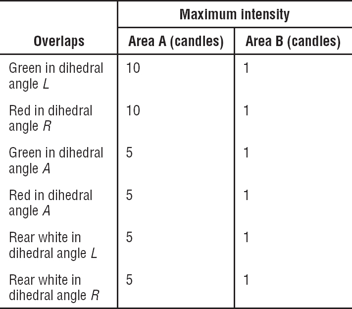
Where—
(a) Area A includes all directions in the adjacent dihedral angle that pass through the light source and intersect the common boundary plane at more than 10 degrees but less than 20 degrees; and
(b) Area B includes all directions in the adjacent dihedral angle that pass through the light source and intersect the common boundary plane at more than 20 degrees.
§29.1397 Color specifications.
Each position light color must have the applicable International Commission on Illumination chromaticity coordinates as follows:
(a) Aviation red—
y is not greater than 0.335; and
z is not greater than 0.002.
(b) Aviation green—
x is not greater than 0.440−0.320y;
x is not greater than y−0.170; and
y is not less than 0.390−0.170x.
(c) Aviation white—
x is not less than 0.300 and not greater than 0.540;
y is not less than x−0.040 or yc−0.010, whichever is the smaller; and
y is not greater than x + 0.020 nor 0.636−0.400x;
Where Ye is the y coordinate of the Planckian radiator for the value of x considered.
[Doc. No. 5084, 29 FR 16150, Dec. 3, 1964, as amended by Amdt. 29-7, 36 FR 12972, July 10, 1971]
§29.1399 Riding light.
(a) Each riding light required for water operation must be installed so that it can—
(1) Show a white light for at least two miles at night under clear atmospheric conditions; and
(2) Show a maximum practicable unbroken light with the rotorcraft on the water.
(b) Externally hung lights may be used.
§29.1401 Anticollision light system.
(a) General. If certification for night operation is requested, the rotorcraft must have an anticollision light system that—
(1) Consists of one or more approved anticollision lights located so that their emitted light will not impair the crew’s vision or detract from the conspicuity of the position lights; and
(2) Meets the requirements of paragraphs (b) through (f) of this section.
(b) Field of coverage. The system must consist of enough lights to illuminate the vital areas around the rotorcraft, considering the physical configuration and flight characteristics of the rotorcraft. The field of coverage must extend in each direction within at least 30 degrees above and 30 degrees below the horizontal plane of the rotorcraft, except that there may be solid angles of obstructed visibility totaling not more than 0.5 steradians.
(c) Flashing characteristics. The arrangement of the system, that is, the number of light sources, beam width, speed of rotation, and other characteristics, must give an effective flash frequency of not less than 40, nor more than 100, cycles per minute. The effective flash frequency is the frequency at which the rotorcraft’s complete anticollision light system is observed from a distance, and applies to each sector of light including any overlaps that exist when the system consists of more than one light source. In overlaps, flash frequencies may exceed 100, but not 180, cycles per minute.
(d) Color. Each anticollision light must be aviation red and must meet the applicable requirements of §29.1397.
(e) Light intensity. The minimum light intensities in any vertical plane, measured with the red filter (if used) and expressed in terms of “effective” intensities must meet the requirements of paragraph (f) of this section. The following relation must be assumed:
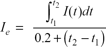
where:
Ie = effective intensity (candles).
I(t) = instantaneous intensity as a function of time.
t2−tl = flash time interval (seconds).
Normally, the maximum value of effective intensity is obtained when t2 and t1 are chosen so that the effective intensity is equal to the instantaneous intensity at t2 and t1.
(f) Minimum effective intensities for anticollision light. Each anticollision light effective intensity must equal or exceed the applicable values in the following table:
Angle above or below the horizontal plane |
Effective intensity (candles) |
0° to 5° |
150 |
5° to 10° |
90 |
10° to 20° |
30 |
20° to 30° |
15 |
[Doc. No. 5084, 29 FR 16150, Dec. 3, 1964, as amended by Amdt. 29-7, 36 FR 12972, July 10, 1971; Amdt. 29-11, 41 FR 5290, Feb. 5, 1976]
SAFETY EQUIPMENT
§29.1411 General.
(a) Accessibility. Required safety equipment to be used by the crew in an emergency, such as automatic liferaft releases, must be readily accessible.
(b) Stowage provisions. Stowage provisions for required emergency equipment must be furnished and must—
(1) Be arranged so that the equipment is directly accessible and its location is obvious; and
(2) Protect the safety equipment from inadvertent damage.
(c) Emergency exit descent device. The stowage provisions for the emergency exit descent device required by §29.809(f) must be at the exits for which they are intended.
(d) Liferafts. Liferafts must be stowed near exits through which the rafts can be launched during an unplanned ditching. Rafts automatically or remotely released outside the rotorcraft must be attached to the rotorcraft by the static line prescribed in §29.1415.
(e) Long-range signaling device. The stowage provisions for the long-range signaling device required by §29.1415 must be near an exit available during an unplanned ditching.
(f) Life preservers. Each life preserver must be within easy reach of each occupant while seated.
§29.1413 Safety belts: passenger warning device.
(a) If there are means to indicate to the passengers when safety belts should be fastened, they must be installed to be operated from either pilot seat.
(b) Each safety belt must be equipped with a metal to metal latching device.
(Secs. 313, 314, and 601 through 610 of the Federal Aviation Act of 1958 (49 U.S.C. 1354, 1355, and 1421 through 1430) and sec. 6(c), Dept. of Transportation Act (49 U.S.C. 1655(c)))
[Doc. No. 5084, 29 FR 16150, Dec. 3, 1964, as amended by Amdt. 29-16 43 FR 46233, Oct. 5, 1978]
§29.1415 Ditching equipment.
(a) Emergency flotation and signaling equipment required by any operating rule of this chapter must meet the requirements of this section.
(b) Each liferaft and each life preserver must be approved. In addition—
(1) Provide not less than two rafts, of an approximately equal rated capacity and buoyancy to accommodate the occupants of the rotorcraft; and
(2) Each raft must have a trailing line, and must have a static line designed to hold the raft near the rotorcraft but to release it if the rotorcraft becomes totally submerged.
(c) Approved survival equipment must be attached to each liferaft.
(d) There must be an approved survival type emergency locator transmitter for use in one life raft.
[Doc. No. 5084, 29 FR 16150, Dec. 3, 1964, as amended by Amdt. 29-8, 36 FR 18722, Sept. 21, 1971; Amdt. 29-19, 45 FR 38348, June 9, 1980; Amdt. 27-26, 55 FR 8005, Mar. 6, 1990; Amdt. 29-33, 59 FR 32057, June 21, 1994]
§29.1419 Ice protection.
(a) To obtain certification for flight into icing conditions, compliance with this section must be shown.
(b) It must be demonstrated that the rotorcraft can be safely operated in the continuous maximum and intermittent maximum icing conditions determined under appendix C of this part within the rotorcraft altitude envelope. An analysis must be performed to establish, on the basis of the rotorcraft’s operational needs, the adequacy of the ice protection system for the various components of the rotorcraft.
(c) In addition to the analysis and physical evaluation prescribed in paragraph (b) of this section, the effectiveness of the ice protection system and its components must be shown by flight tests of the rotorcraft or its components in measured natural atmospheric icing conditions and by one or more of the following tests as found necessary to determine the adequacy of the ice protection system:
(1) Laboratory dry air or simulated icing tests, or a combination of both, of the components or models of the components.
(2) Flight dry air tests of the ice protection system as a whole, or its individual components.
(3) Flight tests of the rotorcraft or its components in measured simulated icing conditions.
(d) The ice protection provisions of this section are considered to be applicable primarily to the airframe. Powerplant installation requirements are contained in Subpart E of this part.
(e) A means must be identified or provided for determining the formation of ice on critical parts of the rotorcraft. Unless otherwise restricted, the means must be available for nighttime as well as daytime operation. The rotorcraft flight manual must describe the means of determining ice formation and must contain information necessary for safe operation of the rotorcraft in icing conditions.
[Amdt. 29-21, 48 FR 4391, Jan. 31, 1983]
MISCELLANEOUS EQUIPMENT
§29.1431 Electronic equipment.
(a) Radio communication and navigation equipment installations must be free from hazards in themselves, in their method of operation, and in their effects on other components, under any critical environmental conditions.
(b) Radio communication and navigation equipment, controls, and wiring must be installed so that operation of any one unit or system of units will not adversely affect the simultaneous operation of any other radio or electronic unit, or system of units, required by this chapter.
§29.1433 Vacuum systems.
(a) There must be means, in addition to the normal pressure relief, to automatically relieve the pressure in the discharge lines from the vacuum air pump when the delivery temperature of the air becomes unsafe.
(b) Each vacuum air system line and fitting on the discharge side of the pump that might contain flammable vapors or fluids must meet the requirements of §29.1183 if they are in a designated fire zone.
(c) Other vacuum air system components in designated fire zones must be at least fire resistant.
§29.1435 Hydraulic systems.
(a) Design. Each hydraulic system must be designed as follows:
(1) Each element of the hydraulic system must be designed to withstand, without detrimental, permanent deformation, any structural loads that may be imposed simultaneously with the maximum operating hydraulic loads.
(2) Each element of the hydraulic system must be designed to withstand pressures sufficiently greater than those prescribed in paragraph (b) of this section to show that the system will not rupture under service conditions.
(3) There must be means to indicate the pressure in each main hydraulic power system.
(4) There must be means to ensure that no pressure in any part of the system will exceed a safe limit above the maximum operating pressure of the system, and to prevent excessive pressures resulting from any fluid volumetric change in lines likely to remain closed long enough for such a change to take place. The possibility of detrimental transient (surge) pressures during operation must be considered.
(5) Each hydraulic line, fitting, and component must be installed and supported to prevent excessive vibration and to withstand inertia loads. Each element of the installation must be protected from abrasion, corrosion, and mechanical damage.
(6) Means for providing flexibility must be used to connect points, in a hydraulic fluid line, between which relative motion or differential vibration exists.
(b) Tests. Each element of the system must be tested to a proof pressure of 1.5 times the maximum pressure to which that element will be subjected in normal operation, without failure, malfunction, or detrimental deformation of any part of the system.
(c) Fire protection. Each hydraulic system using flammable hydraulic fluid must meet the applicable requirements of §§29.861, 29.1183, 29.1185, and 29.1189.
§29.1439 Protective breathing equipment.
(a) If one or more cargo or baggage compartments are to be accessible in flight, protective breathing equipment must be available for an appropriate crewmember.
(b) For protective breathing equipment required by paragraph (a) of this section or by any operating rule of this chapter—
(1) That equipment must be designed to protect the crew from smoke, carbon dioxide, and other harmful gases while on flight deck duty;
(2) That equipment must include—
(i) Masks covering the eyes, nose, and mouth; or
(ii) Masks covering the nose and mouth, plus accessory equipment to protect the eyes; and
(3) That equipment must supply protective oxygen of 10 minutes duration per crewmember at a pressure altitude of 8,000 feet with a respiratory minute volume of 30 liters per minute BTPD.
§29.1457 Cockpit voice recorders.
(a) Each cockpit voice recorder required by the operating rules of this chapter must be approved, and must be installed so that it will record the following:
(1) Voice communications transmitted from or received in the rotorcraft by radio.
(2) Voice communications of flight crewmembers on the flight deck.
(3) Voice communications of flight crewmembers on the flight deck, using the rotorcraft’s interphone system.
(4) Voice or audio signals identifying navigation or approach aids introduced into a headset or speaker.
(5) Voice communications of flight crewmembers using the passenger loudspeaker system, if there is such a system, and if the fourth channel is available in accordance with the requirements of paragraph (c)(4)(ii) of this section.
(6) If datalink communication equipment is installed, all datalink communications, using an approved data message set. Datalink messages must be recorded as the output signal from the communications unit that translates the signal into usable data.
(b) The recording requirements of paragraph (a)(2) of this section may be met—
(1) By installing a cockpit-mounted area microphone, located in the best position for recording voice communications originating at the first and second pilot stations and voice communications of other crewmembers on the flight deck when directed to those stations; or
(2) By installing a continually energized or voice-actuated lip microphone at the first and second pilot stations.
The microphone specified in this paragraph must be so located and, if necessary, the preamplifiers and filters of the recorder must be so adjusted or supplemented, that the recorded communications are intelligible when recorded under flight cockpit noise conditions and played back. The level of intelligibility must be approved by the Administrator. Repeated aural or visual playback of the record may be used in evaluating intelligibility.
(c) Each cockpit voice recorder must be installed so that the part of the communication or audio signals specified in paragraph (a) of this section obtained from each of the following sources is recorded on a separate channel:
(1) For the first channel, from each microphone, headset, or speaker used at the first pilot station.
(2) For the second channel, from each microphone, headset, or speaker used at the second pilot station.
(3) For the third channel, from the cockpit-mounted area microphone, or the continually energized or voice-actuated lip microphones at the first and second pilot stations.
(4) For the fourth channel, from—
(i) Each microphone, headset, or speaker used at the stations for the third and fourth crewmembers; or
(ii) If the stations specified in paragraph (c)(4)(i) of this section are not required or if the signal at such a station is picked up by another channel, each microphone on the flight deck that is used with the passenger loudspeaker system if its signals are not picked up by another channel.
(iii) Each microphone on the flight deck that is used with the rotorcraft’s loudspeaker system if its signals are not picked up by another channel.
(d) Each cockpit voice recorder must be installed so that—
(1)(i) It receives its electrical power from the bus that provides the maximum reliability for operation of the cockpit voice recorder without jeopardizing service to essential or emergency loads.
(ii) It remains powered for as long as possible without jeopardizing emergency operation of the rotorcraft.
(2) There is an automatic means to simultaneously stop the recorder and prevent each erasure feature from functioning, within 10 minutes after crash impact;
(3) There is an aural or visual means for preflight checking of the recorder for proper operation;
(4) Whether the cockpit voice recorder and digital flight data recorder are installed in separate boxes or in a combination unit, no single electrical failure external to the recorder may disable both the cockpit voice recorder and the digital flight data recorder; and
(5) It has an independent power source—
(i) That provides 10 ±1 minutes of electrical power to operate both the cockpit voice recorder and cockpit-mounted area microphone;
(ii) That is located as close as practicable to the cockpit voice recorder; and
(iii) To which the cockpit voice recorder and cockpit-mounted area microphone are switched automatically in the event that all other power to the cockpit voice recorder is interrupted either by normal shutdown or by any other loss of power to the electrical power bus.
(e) The record container must be located and mounted to minimize the probability of rupture of the container as a result of crash impact and consequent heat damage to the record from fire.
(f) If the cockpit voice recorder has a bulk erasure device, the installation must be designed to minimize the probability of inadvertent operation and actuation of the device during crash impact.
(g) Each recorder container must be either bright orange or bright yellow.
(h) When both a cockpit voice recorder and a flight data recorder are required by the operating rules, one combination unit may be installed, provided that all other requirements of this section and the requirements for flight data recorders under this part are met.
[Amdt. 29-6, 35 FR 7293, May 9, 1970, as amended by Amdt. 29-50, 73 FR 12564, Mar. 7, 2008; 74 FR 32800, July 9, 2009; Amdt. 29-52, 75 FR 17045, Apr. 5, 2010]
§29.1459 Flight data recorders.
(a) Each flight recorder required by the operating rules of Subchapter G of this chapter must be installed so that:
(1) It is supplied with airspeed, altitude, and directional data obtained from sources that meet the accuracy requirements of §§29.1323, 29.1325, and 29.1327 of this part, as applicable;
(2) The vertical acceleration sensor is rigidly attached, and located longitudinally within the approved center of gravity limits of the rotorcraft;
(3)(i) It receives its electrical power from the bus that provides the maximum reliability for operation of the flight data recorder without jeopardizing service to essential or emergency loads.
(ii) It remains powered for as long as possible without jeopardizing emergency operation of the rotorcraft.
(4) There is an aural or visual means for perflight checking of the recorder for proper recording of data in the storage medium;
(5) Except for recorders powered solely by the engine-drive electrical generator system, there is an automatic means to simultaneously stop a recorder that has a data erasure feature and prevent each erasure feature from functioning, within 10 minutes after any crash impact; and
(6) Whether the cockpit voice recorder and digital flight data recorder are installed in separate boxes or in a combination unit, no single electrical failure external to the recorder may disable both the cockpit voice recorder and the digital flight data recorder.
(b) Each nonejectable recorder container must be located and mounted so as to minimize the probability of container rupture resulting from crash impact and subsequent damage to the record from fire.
(c) A correlation must be established between the flight recorder readings of airspeed, altitude, and heading and the corresponding readings (taking into account correction factors) of the first pilot’s instruments. This correlation must cover the airspeed range over which the aircraft is to be operated, the range of altitude to which the aircraft is limited, and 360 degrees of heading. Correlation may be established on the ground as appropriate.
(d) Each recorder container must:
(1) Be either bright orange or bright yellow;
(2) Have a reflective tape affixed to its external surface to facilitate its location under water; and
(3) Have an underwater locating device, when required by the operating rules of this chapter, on or adjacent to the container which is secured in such a manner that it is not likely to be separated during crash impact.
(e) When both a cockpit voice recorder and a flight data recorder are required by the operating rules, one combination unit may be installed, provided that all other requirements of this section and the requirements for cockpit voice recorders under this part are met.
[Amdt. 29-25, 53 FR 26145, July 11, 1988; 53 FR 26144, July 11, 1988, as amended by Amdt. 29-50, 73 FR 12564, Mar. 7, 2008; 74 FR 32800, July 9, 2009; Amdt. 29-52, 75 FR 17045, Apr. 5, 2010]
§29.1461 Equipment containing high energy rotors.
(a) Equipment containing high energy rotors must meet paragraph (b), (c), or (d) of this section.
(b) High energy rotors contained in equipment must be able to withstand damage caused by malfunctions, vibration, abnormal speeds, and abnormal temperatures. In addition—
(1) Auxiliary rotor cases must be able to contain damage caused by the failure of high energy rotor blades; and
(2) Equipment control devices, systems, and instrumentation must reasonably ensure that no operating limitations affecting the integrity of high energy rotors will be exceeded in service.
(c) It must be shown by test that equipment containing high energy rotors can contain any failure of a high energy rotor that occurs at the highest speed obtainable with the normal speed control devices inoperative.
(d) Equipment containing high energy rotors must be located where rotor failure will neither endanger the occupants nor adversely affect continued safe flight.
[Amdt. 29-3, 33 FR 971, Jan. 26, 1968]
Subpart G—Operating Limitations and Information
§29.1501 General.
(a) Each operating limitation specified in §§29.1503 through 29.1525 and other limitations and information necessary for safe operation must be established.
(b) The operating limitations and other information necessary for safe operation must be made available to the crewmembers as prescribed in §§29.1541 through 29.1589.
(Secs. 313(a), 601, 603, 604, and 605 of the Federal Aviation Act of 1958 (49 U.S.C. 1354(a), 1421, 1423, 1424, and 1425); and sec. 6(c), Dept. of Transportation Act (49 U.S.C. 1655(c)))
[Amdt. 29-15, 43 FR 2327, Jan. 16, 1978]
OPERATING LIMITATIONS
§29.1503 Airspeed limitations: general.
(a) An operating speed range must be established.
(b) When airspeed limitations are a function of weight, weight distribution, altitude, rotor speed, power, or other factors, airspeed limitations corresponding with the critical combinations of these factors must be established.
§29.1505 Never-exceed speed.
(a) The never-exceed speed, VNE, must be established so that it is—
(1) Not less than 40 knots (CAS); and
(2) Not more than the lesser of—
(i) 0.9 times the maximum forward speeds established under §29.309;
(ii) 0.9 times the maximum speed shown under §§29.251 and 29.629; or
(iii) 0.9 times the maximum speed substantiated for advancing blade tip mach number effects under critical altitude conditions.
(b) VNE may vary with altitude, r.p.m., temperature, and weight, if—
(1) No more than two of these variables (or no more than two instruments integrating more than one of these variables) are used at one time; and
(2) The ranges of these variables (or of the indications on instruments integrating more than one of these variables) are large enough to allow an operationally practical and safe variation of VNE.
(c) For helicopters, a stabilized power-off VNE denoted as VNE (power-off) may be established at a speed less than VNE established pursuant to paragraph (a) of this section, if the following conditions are met:
(1) VNE (power-off) is not less than a speed midway between the power-on VNE and the speed used in meeting the requirements of—
(i) §29.67(a)(3) for Category A helicopters;
(ii) §29.65(a) for Category B helicopters, except multi-engine helicopters meeting the requirements of §29.67(b); and
(iii) §29.67(b) for multi-engine Category B helicopters meeting the requirements of §29.67(b).
(2) VNE (power-off) is—
(i) A constant airspeed;
(ii) A constant amount less than power-on VNE; or
(iii) A constant airspeed for a portion of the altitude range for which certification is requested, and a constant amount less than power-on VNE for the remainder of the altitude range.
(Secs. 313(a), 601, 603, 604, and 605 of the Federal Aviation Act of 1958 (49 U.S.C. 1354(a), 1421, 1423, 1424, and 1425); and sec. 6(c), Dept. of Transportation Act (49 U.S.C. 1655(c)))
[Amdt. 29-3, 33 FR 971, Jan. 26, 1968, as amended by Amdt. 29-15, 43 FR 2327, Jan. 16, 1978; Amdt. 29-24, 49 FR 44440, Nov. 6, 1984]
§29.1509 Rotor speed.
(a) Maximum power-off (autorotation). The maximum power-off rotor speed must be established so that it does not exceed 95 percent of the lesser of—
(1) The maximum design r.p.m. determined under §29.309(b); and
(2) The maximum r.p.m. shown during the type tests.
(b) Minimum power-off. The minimum power-off rotor speed must be established so that it is not less than 105 percent of the greater of—
(1) The minimum shown during the type tests; and
(2) The minimum determined by design substantiation.
(c) Minimum power-on. The minimum power-on rotor speed must be established so that it is—
(1) Not less than the greater of—
(i) The minimum shown during the type tests; and
(ii) The minimum determined by design substantiation; and
(2) Not more than a value determined under §29.33 (a)(1) and (c)(1).
§29.1517 Limiting height-speed envelope.
For Category A rotorcraft, if a range of heights exists at any speed, including zero, within which it is not possible to make a safe landing following power failure, the range of heights and its variation with forward speed must be established, together with any other pertinent information, such as the kind of landing surface.
[Amdt. 29-21, 48 FR 4391, Jan. 31, 1983]
§29.1519 Weight and center of gravity.
The weight and center of gravity limitations determined under §§29.25 and 29.27, respectively, must be established as operating limitations.
§29.1521 Powerplant limitations.
(a) General. The powerplant limitations prescribed in this section must be established so that they do not exceed the corresponding limits for which the engines are type certificated.
(b) Takeoff operation. The powerplant takeoff operation must be limited by—
(1) The maximum rotational speed, which may not be greater than—
(i) The maximum value determined by the rotor design; or
(ii) The maximum value shown during the type tests;
(2) The maximum allowable manifold pressure (for reciprocating engines);
(3) The maximum allowable turbine inlet or turbine outlet gas temperature (for turbine engines);
(4) The maximum allowable power or torque for each engine, considering the power input limitations of the transmission with all engines operating;
(5) The maximum allowable power or torque for each engine considering the power input limitations of the transmission with one engine inoperative;
(6) The time limit for the use of the power corresponding to the limitations established in paragraphs (b)(1) through (5) of this section; and
(7) If the time limit established in paragraph (b)(6) of this section exceeds 2 minutes—
(i) The maximum allowable cylinder head or coolant outlet temperature (for reciprocating engines); and
(ii) The maximum allowable engine and transmission oil temperatures.
(c) Continuous operation. The continuous operation must be limited by—
(1) The maximum rotational speed, which may not be greater than—
(i) The maximum value determined by the rotor design; or
(ii) The maximum value shown during the type tests;
(2) The minimum rotational speed shown under the rotor speed requirements in §29.1509(c).
(3) The maximum allowable manifold pressure (for reciprocating engines);
(4) The maximum allowable turbine inlet or turbine outlet gas temperature (for turbine engines);
(5) The maximum allowable power or torque for each engine, considering the power input limitations of the transmission with all engines operating;
(6) The maximum allowable power or torque for each engine, considering the power input limitations of the transmission with one engine inoperative; and
(7) The maximum allowable temperatures for—
(i) The cylinder head or coolant outlet (for reciprocating engines);
(ii) The engine oil; and
(iii) The transmission oil.
(d) Fuel grade or designation. The minimum fuel grade (for reciprocating engines) or fuel designation (for turbine engines) must be established so that it is not less than that required for the operation of the engines within the limitations in paragraphs (b) and (c) of this section.
(e) Ambient temperature. Ambient temperature limitations (including limitations for winterization installations if applicable) must be established as the maximum ambient atmospheric temperature at which compliance with the cooling provisions of §§29.1041 through 29.1049 is shown.
(f) Two and one-half minute OEI power operation. Unless otherwise authorized, the use of 21⁄2-minute OEI power must be limited to engine failure operation of multiengine, turbine-powered rotorcraft for not longer than 21⁄2 minutes for any period in which that power is used. The use of 21⁄2-minute OEI power must also be limited by—
(1) The maximum rotational speed, which may not be greater than—
(i) The maximum value determined by the rotor design; or
(ii) The maximum value shown during the type tests;
(2) The maximum allowable gas temperature;
(3) The maximum allowable torque; and
(4) The maximum allowable oil temperature.
(g) Thirty-minute OEI power operation. Unless otherwise authorized, the use of 30-minute OEI power must be limited to multiengine, turbine-powered rotorcraft for not longer than 30 minutes after failure of an engine. The use of 30-minute OEI power must also be limited by—
(1) The maximum rotational speed, which may not be greater than—
(i) The maximum value determined by the rotor design; or
(ii) The maximum value shown during the type tests;
(2) The maximum allowable gas temperature;
(3) The maximum allowable torque; and
(4) The maximum allowable oil temperature.
(h) Continuous OEI power operation. Unless otherwise authorized, the use of continuous OEI power must be limited to multiengine, turbine-powered rotorcraft for continued flight after failure of an engine. The use of continuous OEI power must also be limited by—
(1) The maximum rotational speed, which may not be greater than—
(i) The maximum value determined by the rotor design; or
(ii) The maximum value shown during the type tests.
(2) The maximum allowable gas temperature;
(3) The maximum allowable torque; and
(4) The maximum allowable oil temperature.
(i) Rated 30-second OEI power operation. Rated 30-second OEI power is permitted only on multiengine, turbine-powered rotorcraft, also certificated for the use of rated 2-minute OEI power, and can only be used for continued operation of the remaining engine(s) after a failure or precautionary shutdown of an engine. It must be shown that following application of 30-second OEI power, any damage will be readily detectable by the applicable inspections and other related procedures furnished in accordance with Section A29.4 of appendix A of this part and Section A33.4 of appendix A of part 33. The use of 30-second OEI power must be limited to not more than 30 seconds for any period in which that power is used, and by—
(1) The maximum rotational speed which may not be greater than—
(i) The maximum value determined by the rotor design; or
(ii) The maximum value demonstrated during the type tests;
(2) The maximum allowable gas temperature; and
(3) The maximum allowable torque.
(j) Rated 2-minute OEI power operation. Rated 2-minute OEI power is permitted only on multiengine, turbine-powered rotorcraft, also certificated for the use of rated 30-second OEI power, and can only be used for continued operation of the remaining engine(s) after a failure or precautionary shutdown of an engine. It must be shown that following application of 2-minute OEI power, any damage will be readily detectable by the applicable inspections and other related procedures furnished in accordance with Section A29.4 of appendix a of this part and Section A33.4 of appendix A of part 33. The use of 2-minute OEI power must be limited to not more than 2 minutes for any period in which that power is used, and by—
(1) The maximum rotational speed, which may not be greater than—
(i) The maximum value determined by the rotor design; or
(ii) The maximum value demonstrated during the type tests;
(2) The maximum allowable gas temperature; and
(3) The maximum allowable torque.
(Secs. 313(a), 601, 603, 604, and 605 of the Federal Aviation Act of 1958 (49 U.S.C. 1354(a), 1421, 1423, 1424, and 1425); and sec. 6(c), Dept. of Transportation Act (49 U.S.C. 1655(c)))
[Doc. No. 5084, 29 FR 16150, Dec. 3, 1964, as amended by Amdt. 29-1, 30 FR 8778, July 13, 1965; Amdt. 29-3, 33 FR 971, Jan. 26, 1968; Amdt. 29-15, 43 FR 2327, Jan. 16, 1978; Amdt. 29-26, 53 FR 34220, Sept. 2, 1988; Amdt. 29-34, 59 FR 47768, Sept. 16, 1994; Amdt. 29-41, 62 FR 46173, Aug. 29, 1997]
§29.1522 Auxiliary power unit limitations.
If an auxiliary power unit that meets the requirements of TSO-C77 is installed in the rotorcraft, the limitations established for that auxiliary power unit under the TSO including the categories of operation must be specified as operating limitations for the rotorcraft.
(Secs. 313(a), 601, 603, 604, Federal Aviation Act of 1958 (49 U.S.C. 1354(a), 1421, 1423), sec. 6(c), Dept. of Transportation Act (49 U.S.C. 1655(c)))
[Amdt. 29-17, 43 FR 50602, Oct. 30, 1978]
§29.1523 Minimum flight crew.
The minimum flight crew must be established so that it is sufficient for safe operation, considering—
(a) The workload on individual crewmembers;
(b) The accessibility and ease of operation of necessary controls by the appropriate crewmember; and
(c) The kinds of operation authorized under §29.1525.
§29.1525 Kinds of operations.
The kinds of operations (such as VFR, IFR, day, night, or icing) for which the rotorcraft is approved are established by demonstrated compliance with the applicable certification requirements and by the installed equipment.
[Amdt. 29-24, 49 FR 44440, Nov. 6, 1984]
§29.1527 Maximum operating altitude.
The maximum altitude up to which operation is allowed, as limited by flight, structural, powerplant, functional, or equipment characteristics, must be established.
(Secs. 313(a), 601, 603, 604, and 605 of the Federal Aviation Act of 1958 (49 U.S.C. 1354(a), 1421, 1423, 1424, and 1425); and sec. 6(c), Dept. of Transportation Act (49 U.S.C. 1655(c)))
[Amdt. 29-15, 43 FR 2327, Jan. 16, 1978]
§29.1529 Instructions for Continued Airworthiness.
The applicant must prepare Instructions for Continued Airworthiness in accordance with appendix A to this part that are acceptable to the Administrator. The instructions may be incomplete at type certification if a program exists to ensure their completion prior to delivery of the first rotorcraft or issuance of a standard certificate of airworthiness, whichever occurs later.
[Amdt. 29-20, 45 FR 60178, Sept. 11, 1980]
MARKINGS AND PLACARDS
§29.1541 General.
(a) The rotorcraft must contain—
(1) The markings and placards specified in §§29.1545 through 29.1565; and
(2) Any additional information, instrument markings, and placards required for the safe operation of the rotorcraft if it has unusual design, operating or handling characteristics.
(b) Each marking and placard prescribed in paragraph (a) of this section—
(1) Must be displayed in a conspicuous place; and
(2) May not be easily erased, disfigured, or obscured.
§29.1543 Instrument markings: general.
For each instrument—
(a) When markings are on the cover glass of the instrument there must be means to maintain the correct alignment of the glass cover with the face of the dial; and
(b) Each arc and line must be wide enough, and located to be clearly visible to the pilot.
§29.1545 Airspeed indicator.
(a) Each airspeed indicator must be marked as specified in paragraph (b) of this section, with the marks located at the corresponding indicated airspeeds.
(b) The following markings must be made:
(1) A red radial line—
(i) For rotorcraft other than helicopters, at VNE; and
(ii) For helicopters, at a VNE (power-on).
(2) A red, cross-hatched radial line at VNE (power-off) for helicopters, if VNE (power-off) is less than VNE (power-on).
(3) For the caution range, a yellow arc.
(4) For the safe operating range, a green arc.
(Secs. 313(a), 601, 603, 604, and 605 of the Federal Aviation Act of 1958 (49 U.S.C. 1354(a), 1421, 1423, 1424, and 1425); and sec. 6(c), Dept. of Transportation Act (49 U.S.C. 1655(c)))
[Doc. No. 5084, 29 FR 16150, Dec. 3, 1964, as amended by Amdt. 29-15, 43 FR 2327, Jan. 16, 1978; 43 FR 3900, Jan. 30, 1978; Amdt. 29-17, 43 FR 50602, Oct. 30, 1978]
§29.1547 Magnetic direction indicator.
(a) A placard meeting the requirements of this section must be installed on or near the magnetic direction indicator.
(b) The placard must show the calibration of the instrument in level flight with the engines operating.
(c) The placard must state whether the calibration was made with radio receivers on or off.
(d) Each calibration reading must be in terms of magnetic heading in not more than 45 degree increments.
§29.1549 Powerplant instruments.
For each required powerplant instrument, as appropriate to the type of instruments—
(a) Each maximum and, if applicable, minimum safe operating limit must be marked with a red radial or a red line;
(b) Each normal operating range must be marked with a green arc or green line, not extending beyond the maximum and minimum safe limits;
(c) Each takeoff and precautionary range must be marked with a yellow arc or yellow line;
(d) Each engine or propeller range that is restricted because of excessive vibration stresses must be marked with red arcs or red lines; and
(e) Each OEI limit or approved operating range must be marked to be clearly differentiated from the markings of paragraphs (a) through (d) of this section except that no marking is normally required for the 30-second OEI limit.
[Amdt. 29-12, 41 FR 55474, Dec. 20, 1976, as amended by Amdt. 29-26, 53 FR 34220, Sept. 2, 1988; Amdt. 29-34, 59 FR 47769, Sept. 16, 1994]
§29.1551 Oil quantity indicator.
Each oil quantity indicator must be marked with enough increments to indicate readily and accurately the quantity of oil.
§29.1553 Fuel quantity indicator.
If the unusable fuel supply for any tank exceeds one gallon, or five percent of the tank capacity, whichever is greater, a red arc must be marked on its indicator extending from the calibrated zero reading to the lowest reading obtainable in level flight.
§29.1555 Control markings.
(a) Each cockpit control, other than primary flight controls or control whose function is obvious, must be plainly marked as to its function and method of operation.
(b) For powerplant fuel controls—
(1) Each fuel tank selector valve control must be marked to indicate the position corresponding to each tank and to each existing cross feed position;
(2) If safe operation requires the use of any tanks in a specific sequence, that sequence must be marked on, or adjacent to, the selector for those tanks; and
(3) Each valve control for any engine of a multiengine rotorcraft must be marked to indicate the position corresponding to each engine controlled.
(c) Usable fuel capacity must be marked as follows:
(1) For fuel systems having no selector controls, the usable fuel capacity of the system must be indicated at the fuel quantity indicator.
(2) For fuel systems having selector controls, the usable fuel capacity available at each selector control position must be indicated near the selector control.
(d) For accessory, auxiliary, and emergency controls—
(1) Each essential visual position indicator, such as those showing rotor pitch or landing gear position, must be marked so that each crewmember can determine at any time the position of the unit to which it relates; and
(2) Each emergency control must be red and must be marked as to method of operation.
(e) For rotorcraft incorporating retractable landing gear, the maximum landing gear operating speed must be displayed in clear view of the pilot.
[Doc. No. 5084, 29 FR 16150, Dec. 3, 1964, as amended by Amdt. 29-12, 41 FR 55474, Dec. 20, 1976; Amdt. 29-24, 49 FR 44440, Nov. 6, 1984]
§29.1557 Miscellaneous markings and placards.
(a) Baggage and cargo compartments, and ballast location. Each baggage and cargo compartment, and each ballast location must have a placard stating any limitations on contents, including weight, that are necessary under the loading requirements.
(b) Seats. If the maximum allowable weight to be carried in a seat is less than 170 pounds, a placard stating the lesser weight must be permanently attached to the seat structure.
(c) Fuel and oil filler openings. The following apply:
(1) Fuel filler openings must be marked at or near the filler cover with—
(i) The word “fuel”;
(ii) For reciprocating engine powered rotorcraft, the minimum fuel grade;
(iii) For turbine-engine-powered rotorcraft, the permissible fuel designations, except that if impractical, this information may be included in the rotorcraft flight manual, and the fuel filler may be marked with an appropriate reference to the flight manual; and
(iv) For pressure fueling systems, the maximum permissible fueling supply pressure and the maximum permissible defueling pressure.
(2) Oil filler openings must be marked at or near the filler cover with the word “oil”.
(d) Emergency exit placards. Each placard and operating control for each emergency exit must differ in color from the surrounding fuselage surface as prescribed in §29.811(h)(2). A placard must be near each emergency exit control and must clearly indicate the location of that exit and its method of operation.
[Doc. No. 5084, 29 FR 16150, Dec. 3, 1964, as amended by Amdt. 29-3, 33 FR 971, Jan. 26, 1968; Amdt. 29-12, 41 FR 55474, Dec. 20, 1976; Amdt. 29-26, 53 FR 34220, Sept. 2, 1988]
§29.1559 Limitations placard.
There must be a placard in clear view of the pilot that specifies the kinds of operations (VFR, IFR, day, night, or icing) for which the rotorcraft is approved.
[Amdt. 29-24, 49 FR 44440, Nov. 6, 1984]
§29.1561 Safety equipment.
(a) Each safety equipment control to be operated by the crew in emergency, such as controls for automatic liferaft releases, must be plainly marked as to its method of operation.
(b) Each location, such as a locker or compartment, that carries any fire extinguishing, signaling, or other life saving equipment, must be so marked.
(c) Stowage provisions for required emergency equipment must be conspicuously marked to identify the contents and facilitate removal of the equipment.
(d) Each liferaft must have obviously marked operating instructions.
(e) Approved survival equipment must be marked for identification and method of operation.
§29.1565 Tail rotor.
Each tail rotor must be marked so that its disc is conspicuous under normal daylight ground conditions.
[Amdt. 29-3, 33 FR 971, Jan. 26, 1968]
ROTORCRAFT FLIGHT MANUAL
§29.1581 General.
(a) Furnishing information. A Rotorcraft Flight Manual must be furnished with each rotorcraft, and it must contain the following:
(1) Information required by §§29.1583 through 29.1589.
(2) Other information that is necessary for safe operation because of design, operating, or handling characteristics.
(b) Approved information. Each part of the manual listed in §§29.1583 through 29.1589 that is appropriate to the rotorcraft, must be furnished, verified, and approved, and must be segregated, indentified, and clearly distinguished from each unapproved part of that manual.
(c) [Reserved]
(d) Table of contents. Each Rotorcraft Flight Manual must include a table of contents if the complexity of the manual indicates a need for it.
(Secs. 313(a), 601, 603, 604, and 605 of the Federal Aviation Act of 1958 (49 U.S.C. 1354(a), 1421, 1423, 1424, and 1425); and sec. 6(c), Dept. of Transportation Act (49 U.S.C. 1655(c)))
[Amdt. 29-15, 43 FR 2327, Jan. 16, 1978]
§29.1583 Operating limitations.
(a) Airspeed and rotor limitations. Information necessary for the marking of airspeed and rotor limitations on or near their respective indicators must be furnished. The significance of each limitation and of the color coding must be explained.
(b) Powerplant limitations. The following information must be furnished:
(1) Limitations required by §29.1521.
(2) Explanation of the limitations, when appropriate.
(3) Information necessary for marking the instruments required by §§29.1549 through 29.1553.
(c) Weight and loading distribution. The weight and center of gravity limits required by §§29.25 and 29.27, respectively, must be furnished. If the variety of possible loading conditions warrants, instructions must be included to allow ready observance of the limitations.
(d) Flight crew. When a flight crew of more than one is required, the number and functions of the minimum flight crew determined under §29.1523 must be furnished.
(e) Kinds of operation. Each kind of operation for which the rotorcraft and its equipment installations are approved must be listed.
(f) Limiting heights. Enough information must be furnished to allow compliance with §29.1517.
(g) Maximum allowable wind. For Category A rotorcraft, the maximum allowable wind for safe operation near the ground must be furnished.
(h) Altitude. The altitude established under §29.1527 and an explanation of the limiting factors must be furnished.
(i) Ambient temperature. Maximum and minimum ambient temperature limitations must be furnished.
(Secs. 313(a), 601, 603, 604, and 605 of the Federal Aviation Act of 1958 (49 U.S.C. 1354(a), 1421, 1423, 1424, and 1425); and sec. 6(c), Dept. of Transportation Act (49 U.S.C. 1655(c)))
[Doc. No. 5084, 29 FR 16150, Dec. 3, 1964, as amended by Amdt. 29-3, 33 FR 971, Jan. 26, 1968; Amdt. 29-15, 43 FR 2327, Jan. 16, 1978; Amdt. 29-17, 43 FR 50602, Oct. 30, 1978; Amdt. 29-24, 49 FR 44440, Nov. 6, 1984]
§29.1585 Operating procedures.
(a) The parts of the manual containing operating procedures must have information concerning any normal and emergency procedures, and other information necessary for safe operation, including the applicable procedures, such as those involving minimum speeds, to be followed if an engine fails.
(b) For multiengine rotorcraft, information identifying each operating condition in which the fuel system independence prescribed in §29.953 is necessary for safety must be furnished, together with instructions for placing the fuel system in a configuration used to show compliance with that section.
(c) For helicopters for which a VNE (power-off) is established under §29.1505(c), information must be furnished to explain the VNE (power-off) and the procedures for reducing airspeed to not more than the VNE (power-off) following failure of all engines.
(d) For each rotorcraft showing compliance with §29.1353 (c)(6)(ii) or (c)(6)(iii), the operating procedures for disconnecting the battery from its charging source must be furnished.
(e) If the unusable fuel supply in any tank exceeds 5 percent of the tank capacity, or 1 gallon, whichever is greater, information must be furnished which indicates that when the fuel quantity indicator reads “zero” in level flight, any fuel remaining in the fuel tank cannot be used safely in flight.
(f) Information on the total quantity of usable fuel for each fuel tank must be furnished.
(g) For Category B rotorcraft, the airspeeds and corresponding rotor speeds for minimum rate of descent and best glide angle as prescribed in §29.71 must be provided.
(Secs. 313(a), 601, 603, 604, and 605 of the Federal Aviation Act of 1958 (49 U.S.C. 1354(a), 1421, 1423, 1424, and 1425); and sec. 6(c), Dept. of Transportation Act (49 U.S.C. 1655(c)))
[Amdt. 29-2, 32 FR 6914, May 5, 1967, as amended by Amdt. 29-15, 43 FR 2328, Jan. 16, 1978; Amdt. 29-17, 43 FR 50602, Oct. 30, 1978; Amdt. 29-24, 49 FR 44440, Nov. 6, 1984]
§29.1587 Performance information.
Flight manual performance information which exceeds any operating limitation may be shown only to the extent necessary for presentation clarity or to determine the effects of approved optional equipment or procedures. When data beyond operating limits are shown, the limits must be clearly indicated. The following must be provided:
(a) Category A. For each category A rotorcraft, the Rotorcraft Flight Manual must contain a summary of the performance data, including data necessary for the application of any operating rule of this chapter, together with descriptions of the conditions, such as airspeeds, under which this data was determined, and must contain—
(1) The indicated airspeeds corresponding with those determined for takeoff, and the procedures to be followed if the critical engine fails during takeoff;
(2) The airspeed calibrations;
(3) The techniques, associated airspeeds, and rates of descent for autorotative landings;
(4) The rejected takeoff distance determined under §29.62 and the takeoff distance determined under §29.61;
(5) The landing data determined under §29.81 and §29.85;
(6) The steady gradient of climb for each weight, altitude, and temperature for which takeoff data are to be scheduled, along the takeoff path determined in the flight conditions required in §29.67(a)(1) and (a)(2):
(i) In the flight conditions required in §29.67(a)(1) between the end of the takeoff distance and the point at which the rotorcraft is 200 feet above the takeoff surface (or 200 feet above the lowest point of the takeoff profile for elevated heliports);
(ii) In the flight conditions required in §29.67(a)(2) between the points at which the rotorcraft is 200 and 1000 feet above the takeoff surface (or 200 and 1000 feet above the lowest point of the takeoff profile for elevated heliports); and
(7) Out-of-ground effect hover performance determined under §29.49 and the maximum weight for each altitude and temperature condition at which the rotorcraft can safely hover out-of-ground effect in winds of not less than 17 knots from all azimuths. These data must be clearly referenced to the appropriate hover charts.
(b) Category B. For each category B rotorcraft, the Rotorcraft Flight Manual must contain—
(1) The takeoff distance and the climbout speed together with the pertinent information defining the flight path with respect to autorotative landing if an engine fails, including the calculated effects of altitude and temperature;
(2) The steady rates of climb and in-ground-effect hovering ceiling, together with the corresponding airspeeds and other pertinent information, including the calculated effects of altitude and temperature;
(3) The landing distance, appropriate airspeed, and type of landing surface, together with all pertinent information that might affect this distance, including the effects of weight, altitude, and temperature;
(4) The maximum safe wind for operation near the ground;
(5) The airspeed calibrations;
(6) The height-speed envelope except for rotorcraft incorporating this as an operating limitation;
(7) Glide distance as a function of altitude when autorotating at the speeds and conditions for minimum rate of descent and best glide angle, as determined in §29.71;
(8) Out-of-ground effect hover performance determined under §29.49 and the maximum safe wind demonstrated under the ambient conditions for data presented. In addition, the maximum weight for each altitude and temperature condition at which the rotorcraft can safely hover out-of-ground-effect in winds of not less than 17 knots from all azimuths. These data must be clearly referenced to the appropriate hover charts; and
(9) Any additional performance data necessary for the application of any operating rule in this chapter.
[Doc. No. 5084, 29 FR 16150, Dec. 3, 1964, as amended by Amdt. 29-21, 48 FR 4392, Jan. 31, 1983; Amdt. 29-24, 49 FR 44440, Nov. 6, 1984; Amdt. 29-39, 61 FR 21901, May 10, 1996; Amdt. 29-40, 61 FR 21908, May 10, 1996; Amdt. 29-44, 64 FR 45338, Aug. 19, 1999; Amdt. 29-51, 73 FR 11001, Feb. 29, 2008]
§29.1589 Loading information.
There must be loading instructions for each possible loading condition between the maximum and minimum weights determined under §29.25 that can result in a center of gravity beyond any extreme prescribed in §29.27, assuming any probable occupant weights.
Appendix A to Part 29—Instructions for Continued Airworthiness
a29.1 General
(a) This appendix specifies requirements for the preparation of Instructions for Continued Airworthiness as required by §29.1529.
(b) The Instructions for Continued Airworthiness for each rotorcraft must include the Instructions for Continued Airworthiness for each engine and rotor (hereinafter designated “products”), for each appliance required by this chapter, and any required information relating to the interface of those appliances and products with the rotorcraft. If Instructions for Continued Airworthiness are not supplied by the manufacturer of an appliance or product installed in the rotorcraft, the Instructions for Continued Airworthiness for the rotorcraft must include the information essential to the continued airworthiness of the rotorcraft.
(c) The applicant must submit to the FAA a program to show how changes to the Instructions for Continued Airworthiness made by the applicant or by the manufacturers of products and appliances installed in the rotorcraft will be distributed.
a29.2 Format
(a) The Instructions for Continued Airworthiness must be in the form of a manual or manuals as appropriate for the quantity of data to be provided.
(b) The format of the manual or manuals must provide for a practical arrangement.
a29.3 Content
The contents of the manual or manuals must be prepared in the English language. The Instructions for Continued Airworthiness must contain the following manuals or sections, as appropriate, and information:
(a) Rotorcraft maintenance manual or section. (1) Introduction information that includes an explanation of the rotorcraft’s features and data to the extent necessary for maintenance or preventive maintenance.
(2) A description of the rotorcraft and its systems and installations including its engines, rotors, and appliances.
(3) Basic control and operation information describing how the rotorcraft components and systems are controlled and how they operate, including any special procedures and limitations that apply.
(4) Servicing information that covers details regarding servicing points, capacities of tanks, reservoirs, types of fluids to be used, pressures applicable to the various systems, location of access panels for inspection and servicing, locations of lubrication points, the lubricants to be used, equipment required for servicing, tow instructions and limitations, mooring, jacking, and leveling information.
(b) Maintenance Instructions. (1) Scheduling information for each part of the rotorcraft and its engines, auxiliary power units, rotors, accessories, instruments, and equipment that provides the recommended periods at which they should be cleaned, inspected, adjusted, tested, and lubricated, and the degree of inspection, the applicable wear tolerances, and work recommended at these periods. However, the applicant may refer to an accessory, instrument, or equipment manufacturer as the source of this information if the applicant shows that the item has an exceptionally high degree of complexity requiring specialized maintenance techniques, test equipment, or expertise. The recommended overhaul periods and necessary cross references to the Airworthiness Limitations section of the manual must also be included. In addition, the applicant must include an inspection program that includes the frequency and extent of the inspections necessary to provide for the continued airworthiness of the rotorcraft.
(2) Troubleshooting information describing probable malfunctions, how to recognize those malfunctions, and the remedial action for those malfunctions.
(3) Information describing the order and method of removing and replacing products and parts with any necessary precautions to be taken.
(4) Other general procedural instructions including procedures for system testing during ground running, symmetry checks, weighing and determining the center of gravity, lifting and shoring, and storage limitations.
(c) Diagrams of structural access plates and information needed to gain access for inspections when access plates are not provided.
(d) Details for the application of special inspection techniques including radiographic and ultrasonic testing where such processes are specified.
(e) Information needed to apply protective treatments to the structure after inspection.
(f) All data relative to structural fasteners such as identification, discard recommendations, and torque values.
(g) A list of special tools needed.
a29.4 Airworthiness Limitations Section
The Instructions for Continued Airworthiness must contain a section titled Airworthiness Limitations that is segregated and clearly distinguishable from the rest of the document. This section must set forth each mandatory replacement time, structural inspection interval, and related structural inspection procedure required for type certification. If the Instructions for Continued Airworthiness consist of multiple documents, the section required by this paragraph must be included in the principal manual. This section must contain a legible statement in a prominent location that reads: “The Airworthiness Limitations section is FAA approved and specifies maintenance required under §§43.16 and 91.403 of the Federal Aviation Regulations unless an alternative program has been FAA approved.”
[Amdt. 29-20, 45 FR 60178, Sept. 11, 1980, as amended by Amdt. 29-27, 54 FR 34330, Aug. 18, 1989; Amdt. 29-54, 76 FR 74664, Dec. 1, 2011]
Appendix B to Part 29—Airworthiness Criteria for Helicopter Instrument Flight
I. General. A transport category helicopter may not be type certificated for operation under the instrument flight rules (IFR) of this chapter unless it meets the design and installation requirements contained in this appendix.
II. Definitions. (a) VYI means instrument climb speed, utilized instead of VY for compliance with the climb requirements for instrument flight.
(b) VNEI means instrument flight never exceed speed, utilized instead of VNE for compliance with maximum limit speed requirements for instrument flight.
(c) VMINI means instrument flight minimum speed, utilized in complying with minimum limit speed requirements for instrument flight.
III. Trim. It must be possible to trim the cyclic, collective, and directional control forces to zero at all approved IFR airspeeds, power settings, and configurations appropriate to the type.
IV. Static longitudinal stability. (a) General. The helicopter must possess positive static longitudinal control force stability at critical combinations of weight and center of gravity at the conditions specified in paragraphs IV (b) through (f) of this appendix. The stick force must vary with speed so that any substantial speed change results in a stick force clearly perceptible to the pilot. The airspeed must return to within 10 percent of the trim speed when the control force is slowly released for each trim condition specified in paragraphs IV (b) through (f) of this appendix.
(b) Climb. Stability must be shown in climb thoughout the speed range 20 knots either side of trim with—
(1) The helicopter trimmed at VYI;
(2) Landing gear retracted (if retractable); and
(3) Power required for limit climb rate (at least 1,000 fpm) at VYI or maximum continuous power, whichever is less.
(c) Cruise. Stability must be shown throughout the speed range from 0.7 to 1.1 VH or VNEI, whichever is lower, not to exceed ±20 knots from trim with—
(1) The helicopter trimmed and power adjusted for level flight at 0.9 VH or 0.9 VNEI, whichever is lower; and
(2) Landing gear retracted (if retractable).
(d) Slow cruise. Stability must be shown throughout the speed range from 0.9 VMINI to 1.3 VMINI or 20 knots above trim speed, whichever is greater, with—
(1) The helicopter trimmed and power adjusted for level flight at 1.1 VMINI; and
(2) Landing gear retracted (if retractable).
(e) Descent. Stability must be shown throughout the speed range 20 knots either side of trim with—
(1) The helicopter trimmed at 0.8 VH or 0.8 VNEI (or 0.8 VLE for the landing gear extended case), whichever is lower;
(2) Power required for 1,000 fpm descent at trim speed; and
(3) Landing gear extended and retracted, if applicable.
(f) Approach. Stability must be shown throughout the speed range from 0.7 times the minimum recommended approach speed to 20 knots above the maximum recommended approach speed with—
(1) The helicopter trimmed at the recommended approach speed or speeds;
(2) Landing gear extended and retracted, if applicable; and
(3) Power required to maintain a 3° glide path and power required to maintain the steepest approach gradient for which approval is requested.
V. Static Lateral Directional Stability
(a) Static directional stability must be positive throughout the approved ranges of airspeed, power, and vertical speed. In straight and steady sideslips up to ±10° from trim, directional control position must increase without discontinuity with the angle of sideslip, except for a small range of sideslip angles around trim. At greater angles up to the maximum sideslip angle appropriate to the type, increased directional control position must produce an increased angle of sideslip. It must be possible to maintain balanced flight without exceptional pilot skill or alertness.
(b) During sideslips up to ±10° from trim throughout the approved ranges of airspeed, power, and vertical speed there must be no negative dihedral stability perceptible to the pilot through lateral control motion or force. Longitudinal cyclic movement with sideslip must not be excessive.
VI. Dynamic stability. (a) Any oscillation having a period of less than 5 seconds must damp to 1⁄2 amplitude in not more than one cycle.
(b) Any oscillation having a period of 5 seconds or more but less than 10 seconds must damp to 1⁄2 amplitude in not more than two cycles.
(c) Any oscillation having a period of 10 seconds or more but less than 20 seconds must be damped.
(d) Any oscillation having a period of 20 seconds or more may not achieve double amplitude in less than 20 seconds.
(e) Any aperiodic response may not achieve double amplitude in less than 9 seconds.
VII. Stability Augmentation System (SAS)
(a) If a SAS is used, the reliability of the SAS must be related to the effects of its failure. Any SAS failure condition that would prevent continued safe flight and landing must be extremely improbable. It must be shown that, for any failure condition of the SAS that is not shown to be extremely improbable—
(1) The helicopter is safely controllable when the failure or malfunction occurs at any speed or altitude within the approved IFR operating limitations; and
(2) The overall flight characteristics of the helicopter allow for prolonged instrument flight without undue pilot effort. Additional unrelated probable failures affecting the control system must be considered. In addition—
(i) The controllability and maneuverability requirements in Subpart B must be met throughout a practical flight envelope;
(ii) The flight control, trim, and dynamic stability characteristics must not be impaired below a level needed to allow continued safe flight and landing;
(iii) For Category A helicopters, the dynamic stability requirements of Subpart B must also be met throughout a practical flight envelope; and
(iv) The static longitudinal and static directional stability requirements of Subpart B must be met throughout a practical flight envelope.
(b) The SAS must be designed so that it cannot create a hazardous deviation in flight path or produce hazardous loads on the helicopter during normal operation or in the event of malfunction or failure, assuming corrective action begins within an appropriate period of time. Where multiple systems are installed, subsequent malfunction conditions must be considered in sequence unless their occurrence is shown to be improbable.
VIII. Equipment, systems, and installation. The basic equipment and installation must comply with Subpart F of Part 29 through Amendment 29-14, with the following exceptions and additions:
(a) Flight and navigation instruments. (1) A magnetic gyro-stabilized direction indicator instead of the gyroscopic direction indicator required by §29.1303(h); and
(2) A standby attitude indicator which meets the requirements of §§29.1303(g)(1) through (7), instead of a rate-of-turn indicator required by §29.1303(g). If standby batteries are provided, they may be charged from the aircraft electrical system if adequate isolation is incorporated. The system must be designed so that the standby batteries may not be used for engine starting.
(b) Miscellaneous requirements. (1) Instrument systems and other systems essential for IFR flight that could be adversely affected by icing must be provided with adequate ice protection whether or not the rotorcraft is certificated for operation in icing conditions.
(2) There must be means in the generating system to automatically de-energize and disconnect from the main bus any power source developing hazardous overvoltage.
(3) Each required flight instrument using a power supply (electric, vacuum, etc.) must have a visual means integral with the instrument to indicate the adequacy of the power being supplied.
(4) When multiple systems performing like functions are required, each system must be grouped, routed, and spaced so that physical separation between systems is provided to ensure that a single malfunction will not adversely affect more than one system.
(5) For systems that operate the required flight instruments at each pilot’s station—
(i) Only the required flight instruments for the first pilot may be connected to that operating system;
(ii) Additional instruments, systems, or equipment may not be connected to an operating system for a second pilot unless provisions are made to ensure the continued normal functioning of the required instruments in the event of any malfunction of the additional instruments, systems, or equipment which is not shown to be extremely improbable;
(iii) The equipment, systems, and installations must be designed so that one display of the information essential to the safety of flight which is provided by the instruments will remain available to a pilot, without additional crew-member action, after any single failure or combination of failures that is not shown to be extremely improbable; and
(iv) For single-pilot configurations, instruments which require a static source must be provided with a means of selecting an alternate source and that source must be calibrated.
(6) In determining compliance with the requirements of §29.1351(d)(2), the supply of electrical power to all systems necessary for flight under IFR must be included in the evaluation.
(c) Thunderstorm lights. In addition to the instrument lights required by §29.1381(a), thunderstorm lights which provide high intensity white flood lighting to the basic flight instruments must be provided. The thunderstorm lights must be installed to meet the requirements of §29.1381(b).
IX. Rotorcraft Flight Manual. A Rotorcraft Flight Manual or Rotorcraft Flight Manual IFR Supplement must be provided and must contain—
(a) Limitations. The approved IFR flight envelope, the IFR flightcrew composition, the revised kinds of operation, and the steepest IFR precision approach gradient for which the helicopter is approved;
(b) Procedures. Required information for proper operation of IFR systems and the recommended procedures in the event of stability augmentation or electrical system failures; and
(c) Performance. If VYI differs from VY, climb performance at VYI and with maximum continuous power throughout the ranges of weight, altitude, and temperature for which approval is requested.
[Amdt. 29-21, 48 FR 4392, Jan. 31, 1983, as amended by Amdt. 29-31, 55 FR 38967, Sept. 21, 1990; 55 FR 41309, Oct. 10, 1990; Amdt. 29-40, 61 FR 21908, May 10, 1996; Amdt. 29-51, 73 FR 11002, Feb. 29, 2008]
APPENDIX C TO PART 29—ICING CERTIFICATION
(a) Continuous maximum icing. The maximum continuous intensity of atmospheric icing conditions (continuous maximum icing) is defined by the variables of the cloud liquid water content, the mean effective diameter of the cloud droplets, the ambient air temperature, and the interrelationship of these three variables as shown in Figure 1 of this appendix. The limiting icing envelope in terms of altitude and temperature is given in Figure 2 of this appendix. The interrelationship of cloud liquid water content with drop diameter and altitude is determined from Figures 1 and 2. The cloud liquid water content for continuous maximum icing conditions of a horizontal extent, other than 17.4 nautical miles, is determined by the value of liquid water content of Figure 1, multiplied by the appropriate factor from Figure 3 of this appendix.
(b) Intermittent maximum icing. The intermittent maximum intensity of atmospheric icing conditions (intermittent maximum icing) is defined by the variables of the cloud liquid water content, the mean effective diameter of the cloud droplets, the ambient air temperature, and the interrelationship of these three variables as shown in Figure 4 of this appendix. The limiting icing envelope in terms of altitude and temperature is given in Figure 5 of this appendix. The interrelationship of cloud liquid water content with drop diameter and altitude is determined from Figures 4 and 5. The cloud liquid water content for intermittent maximum icing conditions of a horizontal extent, other than 2.6 nautical miles, is determined by the value of cloud liquid water content of Figure 4 multiplied by the appropriate factor in Figure 6 of this appendix.


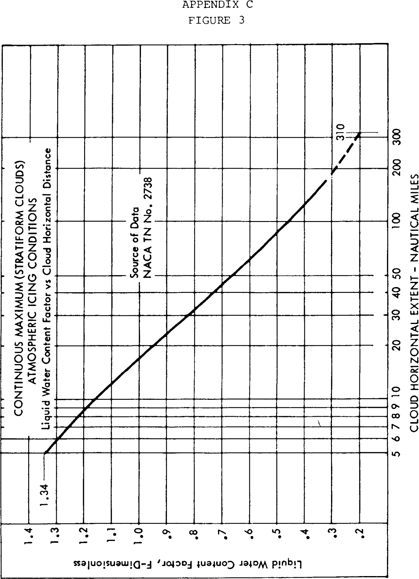


[Amdt. 29-21, 48 FR 4393, Jan. 31, 1983]
Appendix D to Part 29—Criteria for Demonstration of Emergency Evacuation Procedures Under §29.803
(a) The demonstration must be conducted either during the dark of the night or during daylight with the dark of night simulated. If the demonstration is conducted indoors during daylight hours, it must be conducted inside a darkened hangar having doors and windows covered. In addition, the doors and windows of the rotorcraft must be covered if the hangar illumination exceeds that of a moonless night. Illumination on the floor or ground may be used, but it must be kept low and shielded against shining into the rotorcraft’s windows or doors.
(b) The rotorcraft must be in a normal attitude with landing gear extended.
(c) Safety equipment such as mats or inverted liferafts may be placed on the floor or ground to protect participants. No other equipment that is not part of the rotorcraft’s emergency evacuation equipment may be used to aid the participants in reaching the ground.
(d) Except as provided in paragraph (a) of this appendix, only the rotorcraft’s emergency lighting system may provide illumination.
(e) All emergency equipment required for the planned operation of the rotorcraft must be installed.
(f) Each external door and exit and each internal door or curtain must be in the takeoff configuration.
(g) Each crewmember must be seated in the normally assigned seat for takeoff and must remain in that seat until receiving the signal for commencement of the demonstration. For compliance with this section, each crewmember must be—
(1) A member of a regularly scheduled line crew; or
(2) A person having knowledge of the operation of exits and emergency equipment.
(h) A representative passenger load of persons in normal health must be used as follows:
(1) At least 25 percent must be over 50 years of age, with at least 40 percent of these being females.
(2) The remaining, 75 percent or less, must be 50 years of age or younger, with at least 30 percent of these being females.
(3) Three life-size dolls, not included as part of the total passenger load, must be carried by passengers to simulate live infants 2 years old or younger, except for a total passenger load of fewer than 44 but more than 19, one doll must be carried. A doll is not required for a 19 or fewer passenger load.
(4) Crewmembers, mechanics, and training personnel who maintain or operate the rotorcraft in the normal course of their duties may not be used as passengers.
(i) No passenger may be assigned a specific seat except as the Administrator may require. Except as required by paragraph (1) of this appendix, no employee of the applicant may be seated next to an emergency exit, except as allowed by the Administrator.
(j) Seat belts and shoulder harnesses (as required) must be fastened.
(k) Before the start of the demonstration, approximately one-half of the total average amount of carry-on baggage, blankets, pillows, and other similar articles must be distributed at several locations in the aisles and emergency exit access ways to create minor obstructions.
(l) No prior indication may be given to any crewmember or passenger of the particular exits to be used in the demonstration.
(m) The applicant may not practice, rehearse, or describe the demonstration for the participants nor may any participant have taken part in this type of demonstration within the preceding 6 months.
(n) A pretakeoff passenger briefing may be given. The passengers may also be advised to follow directions of crewmembers, but not be instructed on the procedures to be followed in the demonstration.
(o) If safety equipment, as allowed by paragraph (c) of this appendix, is provided, either all passenger and cockpit windows must be blacked out or all emergency exits must have safety equipment to prevent disclosure of the available emergency exits.
(p) Not more than 50 percent of the emergency exits in the sides of the fuselage of a rotorcraft that meet all of the requirements applicable to the required emergency exits for that rotorcraft may be used for demonstration. Exits that are not to be used for the demonstration must have the exit handle deactivated or must be indicated by red lights, red tape, or other acceptable means placed outside the exits to indicate fire or other reasons why they are unusable. The exits to be used must be representative of all the emergency exits on the rotorcraft and must be designated by the applicant, subject to approval by the Administrator. If installed, at least one floor level exit (Type I; §29.807(a)(1)) must be used as required by §29.807(c).
(q) All evacuees must leave the rotorcraft by a means provided as part of the rotorcraft’s equipment.
(r) Approved procedures must be fully utilized during the demonstration.
(s) The evacuation time period is completed when the last occupant has evacuated the rotorcraft and is on the ground.
[Amdt. 27-26, 55 FR 8005, Mar. 6, 1990]
Appendix E to Part 29—HIRF Environments and Equipment HIRF Test Levels
This appendix specifies the HIRF environments and equipment HIRF test levels for electrical and electronic systems under §29.1317. The field strength values for the HIRF environments and laboratory equipment HIRF test levels are expressed in root-mean-square units measured during the peak of the modulation cycle.
(a) HIRF environment I is specified in the following table:
TABLE I.—HIRF ENVIRONMENT I

In this table, the higher field strength applies at the frequency band edges.
(b) HIRF environment II is specified in the following table:
TABLE II.—HIRF ENVIRONMENT II
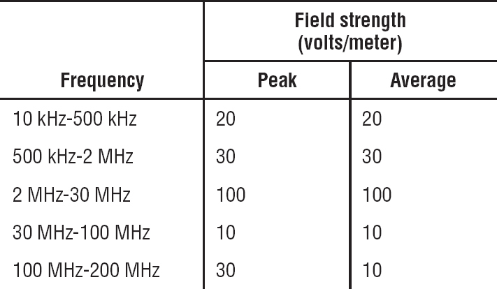
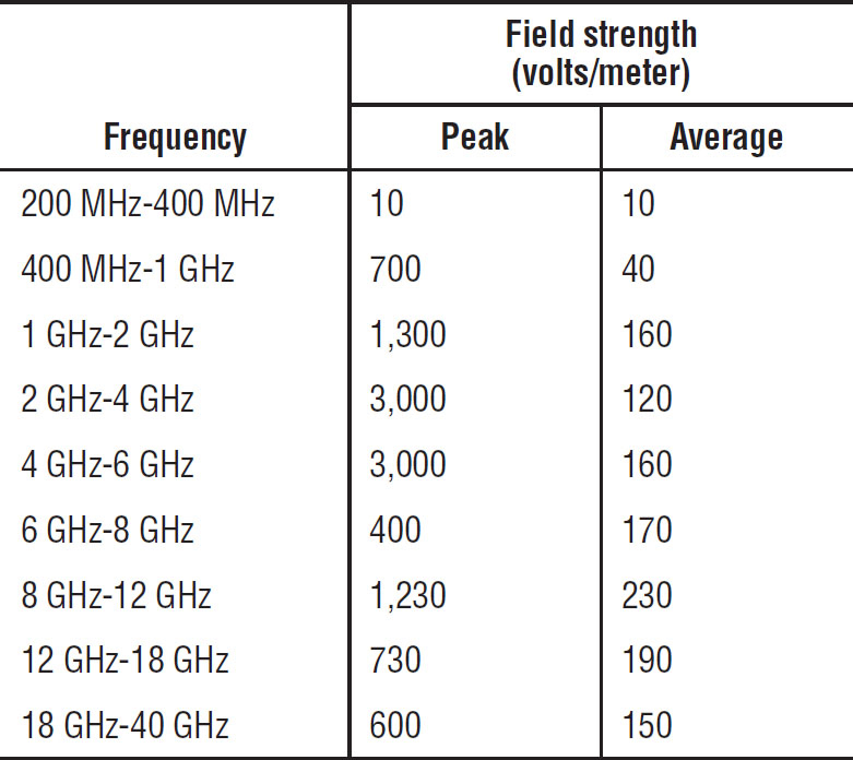
In this table, the higher field strength applies at the frequency band edges.
(c) HIRF environment III is specified in the following table:
TABLE III.—HIRF ENVIRONMENT III
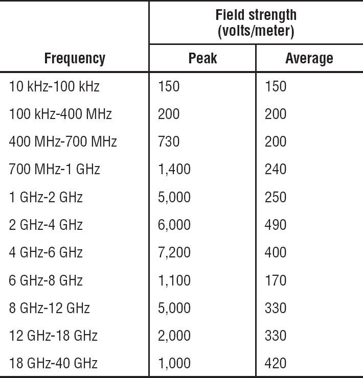
In this table, the higher field strength applies at the frequency band edges.
(d) Equipment HIRF Test Level 1. (1) From 10 kilohertz (kHz) to 400 megahertz (MHz), use conducted susceptibility tests with continuous wave (CW) and 1 kHz square wave modulation with 90 percent depth or greater. The conducted susceptibility current must start at a minimum of 0.6 milliamperes (mA) at 10 kHz, increasing 20 decibel (dB) per frequency decade to a minimum of 30 mA at 500 kHz.
(2) From 500 kHz to 40 MHz, the conducted susceptibility current must be at least 30 mA.
(3) From 40 MHz to 400 MHz, use conducted susceptibility tests, starting at a minimum of 30 mA at 40 MHz, decreasing 20 dB per frequency decade to a minimum of 3 mA at 400 MHz.
(4) From 100 MHz to 400 MHz, use radiated susceptibility tests at a minimum of 20 volts per meter (V/m) peak with CW and 1 kHz square wave modulation with 90 percent depth or greater.
(5) From 400 MHz to 8 gigahertz (GHz), use radiated susceptibility tests at a minimum of 150 V/m peak with pulse modulation of 4 percent duty cycle with a 1 kHz pulse repetition frequency. This signal must be switched on and off at a rate of 1 Hz with a duty cycle of 50 percent.
(e) Equipment HIRF Test Level 2. Equipment HIRF test level 2 is HIRF environment II in table II of this appendix reduced by acceptable aircraft transfer function and attenuation curves. Testing must cover the frequency band of 10 kHz to 8 GHz.
(f) Equipment HIRF Test Level 3. (1) From 10 kHz to 400 MHz, use conducted susceptibility tests, starting at a minimum of 0.15 mA at 10 kHz, increasing 20 dB per frequency decade to a minimum of 7.5 mA at 500 kHz.
(2) From 500 kHz to 40 MHz, use conducted susceptibility tests at a minimum of 7.5 mA.
(3) From 40 MHz to 400 MHz, use conducted susceptibility tests, starting at a minimum of 7.5 mA at 40 MHz, decreasing 20 dB per frequency decade to a minimum of 0.75 mA at 400 MHz.
(4) From 100 MHz to 8 GHz, use radiated susceptibility tests at a minimum of 5 V/m.
[Doc. No. FAA-2006-23657, 72 FR 44028, Aug. 6, 2007]