Abig part of system configuration is understanding what CMOS is and how the different settings within CMOS can help you troubleshoot a system. A wonderful talent to have as an A+ Certified Professional is the ability to understand CMOS and its functionality. Although CMOS doesn’t seem like a place where you’d need to go every day, many PC-related problems can be solved in CMOS.
In this chapter, you learn some of the common CMOS options that are found in modern systems. Keep in mind that these options might be labeled differently on your system or might not even exist on your system, as the CMOS setup program is unique to each system. For example, the CMOS setup program on a Lenovo system differs from that of a Dell even though the concept of CMOS remains the same.
I start the chapter with a discussion of the system BIOS and then compare it against CMOS; the two are closely related and are often confused by many IT professionals.
BIOS versus CMOS
BIOS — basic input-output system — is the low-level instructions the system uses to communicate with the system devices. This is different than CMOS (complementary metal-oxide semiconductor), which is simply an inventory list of the configuration information for the system, containing information such as the hard drive space and amount of memory that exists on the system. Keep this in mind:
CMOS is the inventory list.
BIOS is the actual code that is run to communicate with those devices.
Originally, the BIOS was stored in a ROM chip on the motherboard. Because of this, you used to have to replace the entire chip with a new chip to update the BIOS. Today’s systems, however, have the BIOS code stored in an EEPROM (electronically erasable programmable read-only memory) chip located on the motherboard. (For more information on ROM and EEPROM, check out the memory topic in Chapter 3 of this minibook.) The chip that contains the BIOS code is called the BIOS chip. The BIOS chip should be easy to find — it’s usually rectangular and clearly labeled, typically with the name of the manufacturer of the BIOS chip and the date when the chip was created. In Figure 4-1, the BIOS chip is the chip with the white label indicated with a number 1.
FIGURE 4-1: The BIOS chip (an EEPROM chip located on the motherboard) contains the BIOS code.
Along with the low-level code, the BIOS also contains the POST (power-on self-test) and the CMOS setup program. The POST is a self-diagnostics routine that the system goes through each time it boots up. This self-diagnostic checks to see that each device listed in CMOS actually exists on the system. The POST also tests devices, such as I/O (input/output) ports and memory, to verify not only that they exist but also that they still function.
You use the CMOS setup program, which is stored in the BIOS, to navigate through the CMOS settings. However, the BIOS does not contain the settings themselves. As you find out in the upcoming section, “Understanding CMOS,” the CMOS settings are maintained in CMOS RAM.
Upgrading the System BIOS
When your system was designed, its BIOS program code was designed to work with very specific devices. As you know, computer technology changes very quickly, almost overnight. So, what can you do if you have an older system and you want to update its capabilities?
The BIOS dictates a system’s capabilities. For example, assume that the BIOS on your old computer does not support virtualization (more on this later). It is possible that after you update the BIOS code your system may have virtualization support. As far as the current BIOS in your system is concerned, there is no such thing as virtualization. Thus, you need an upgraded BIOS to make the system understand!
Another example of a good time to upgrade the BIOS code in hardware is with a wireless home router. A few years back, I purchased my first wireless router. I knew that I wanted to configure the wireless network to limit which Media Access Control (MAC) addresses (network cards) could connect to the wireless network. Unfortunately, there was no such setting in the configuration screens of the wireless router, so I went to the manufacturer’s website and updated the BIOS in the router. After I completed the upgrade of the router, the setting I was looking for suddenly appeared on the configuration screens! The point is that it is extremely common to upgrade the BIOS on devices to make sure that the device is up to date with the current trends.
Performing the BIOS upgrade
In the past, with much older systems, you would upgrade the BIOS by completely replacing the BIOS chip. Back then, BIOS was stored on a ROM (read-only memory) chip, which could not be written to. So the only way to get new BIOS code was to replace the entire chip!
Today’s systems use a modified version of the ROM chip: an EEPROM chip. To upgrade the program code on an EEPROM chip, you do not need to physically replace the chip; you just run a software program that is designed to rewrite the program code.
To upgrade the BIOS, you need to get the update program from the manufacturer. You can usually find the program on the manufacturer’s website (and it is usually downloadable), or you may be able to order a CD from the manufacturer. Be sure to follow the manufacturer’s directions on how to apply the update to your BIOS.
When updating your BIOS, you first go to the manufacturer's website and download the BIOS update program. After you download the BIOS update program, you then run the program on your system, and it rewrites the BIOS code on the BIOS chip. Because you are writing to this ROM chip with a special program, the ROM is called a flash ROM, where flashing is the process of rewriting the program code.
Potential issues with BIOS upgrading
If you decide to perform a BIOS upgrade, consider these few words of caution:
Be sure you’re applying the correct BIOS update for system. You want to make sure that you are aware of the manufacturer for your BIOS before you look for an update. With this information, you can go to the manufacturer’s website and download the update. You will not be able to mix BIOS codes between manufacturers. For example, you cannot update your Compaq system with a BIOS update from Dell.
Be sure that you not only have the BIOS update for the correct system, but also that the BIOS update you have is designed for your version of the BIOS. Each BIOS has a revision number or version number. The developers of the BIOS update program might place a version check into the BIOS update, but you cannot be sure of that. So, as a result, be sure to double-check that the BIOS update you are running is for the BIOS version you have.
Installing the wrong BIOS version can cause the system to become dysfunctional. If you can’t find a BIOS version number, use the BIOS date to decide which update to download. The current BIOS version or date can be located within CMOS or seen with the BIOS manufacturer on the screen during boot-up, as shown in Figure 4-2.
When you start a BIOS update, be sure that you complete it. Rewriting only a portion of the BIOS code (whether as a result of an accidental shutdown or power loss during the writing process) can cause the system to become dysfunctional. The actual BIOS update should take only a few seconds, so try not to disrupt the BIOS update after it starts.
FIGURE 4-2: Identifying the BIOS version by starting up the system.
As a way to prevent accidental writing to the BIOS code, some motherboards ship with a jumper on the board that must be removed to write to the BIOS chip. When you want to upgrade the BIOS and you have the correct BIOS update, you remove the jumper and then run the BIOS update. After updating the BIOS, you place the jumper back.
Now that you have an understanding of what the BIOS is used for and how to update the BIOS, it is time to move on to CMOS and the different computer settings that can be controlled through CMOS.
Understanding CMOS
As I mention earlier, CMOS contains the computer’s inventory list and advanced setup options. It can be considered an inventory list because it contains a record of all the devices connected to the system, such as the floppy drive, the hard drive, memory, and so on. Not only does CMOS list the devices, but it also dictates their capacity — for example, whether the system supports 2GB or 8GB of memory.
During the boot process, the system compares its inventory list with what it detects during boot-up. If there are any discrepancies, the system typically gives you an error and takes you into CMOS right away, asking you to save the new change. For example, assume that your system has 2GB of RAM and you add another 2GB of RAM. When you power up the system, the system compares what it had in inventory (2GB) the last time it booted with what it sees now (4GB). Because there is a difference, CMOS reports a memory size error and gives you the opportunity to save the new changes to CMOS. CMOS doesn’t know whether the difference is for the better; it sees a difference, so it reports an error. Because CMOS detected the new memory, all you have to do is save the changes to the inventory list and reboot.
Looking at the previous example, if you choose not to save the settings, you will get the memory size error the next time you start the computer. To prevent the error from appearing again, save the changes to CMOS. This way, the values that are detected are equal to what is stored in CMOS.
Before discussing the different CMOS settings, it’s important to know how to enter the CMOS setup program. Figuring this out is difficult on some systems yet extremely easy on others. Some systems display a message on boot-up that indicates what keystroke (often Delete, F1, or F2) to use to enter the CMOS setup program. IBM systems typically use F1 (refer to Figure 4-2); Dell systems today typically use F2 or Delete, while older Compaq systems typically used F10, or sometimes F2, as is the case with my Compaq laptops. The point here is that each manufacturer may use a different keystroke to enter CMOS.
In some older systems, you enter CMOS by holding down multiple keys at the same time during boot-up — Ctrl+Alt+S or Ctrl+Alt+Insert, for example. Entering into these systems is a little trickier, so reviewing your documentation is helpful. (Note that it has been a long time since I have seen a system that uses these three-key combinations to enter the CMOS setup program.) Table 4-1 summarizes popular keystrokes used to enter CMOS, based on the manufacturer of the BIOS. (Remember that the CMOS setup program is stored in BIOS.)
CMOS information is held in CMOS RAM, which is volatile memory that can maintain its data during shutdowns or power loss by using a small battery located on the motherboard. Thus, if the battery on the motherboard loses power, the CMOS data is also lost. Figure 4-3 shows a CMOS battery on a system board.
FIGURE 4-3: The CMOS battery on the system board is responsible for powering CMOS RAM.
The CMOS configuration is stored in CMOS RAM. Because RAM loses its contents when the system is powered off, the motherboard has a small battery that maintains enough of a charge that CMOS RAM can maintain its data — thus allowing the system to retain the CMOS information between reboots.
Viewing Basic CMOS Settings
In this section, you find out about common CMOS setup options, also known as BIOS component information, and their purposes. These CMOS settings are consistent with most systems and have become fairly standard settings to view or change through the CMOS setup program when troubleshooting a system.
After you enter the CMOS setup program, you may see an introductory screen, such as the one shown in Figure 4-4, displaying options that can be changed, which allows you to control the system configuration.
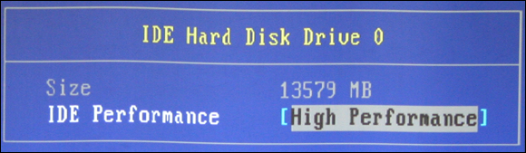
Within the CMOS setup program, you can find the size of the hard drive. CMOS displays the size of the hard drive based on what is detected during startup. The hard drive size is displayed in CMOS, as shown in Figure 4-5.
The hard drives are typically displayed in today’s systems as individual storage devices. You simply highlight the storage device and press enter to view the details. On older EIDE/PATA systems, the drives show as primary master, primary slave, secondary master, and secondary slave. Each entry shows the label of the drive; you highlight it in CMOS and then press Enter to view the details on the drive. The details can include the size of the drive, its geometry, and any settings for the drive.
On some older systems, you could change the CMOS from autodetect to manual so that you can specify the dimensions of the drive — overriding what was detected. Specifying the dimensions of the drive involves looking on the back of the drive to find out how many sectors, cylinders, and heads the drive contains — which dictates the size of the drive. When you know the dimensions, you can input these dimensions into CMOS (after switching from autodetect to manual). CMOS calculates the size of the drive based on the dimensions you input.
On older systems, you specify the hard drive size by specifying a drive type, which is a number representing a drive of a specific size. For example, a Type 2 drive might be 1.2GB in size, and a Type 10 drive might be 1.5GB in size. (The actual values of hard drive types vary from system to system and are usually displayed along with the type.) There is also a custom type on older systems — usually Type 47 — which enables you to specify the dimensions of the drive (sectors, cylinders, heads); CMOS can then calculate the size in megabytes for you after you input the dimensions.
Optical drive
The CMOS stores basic information related to optical drives such as CD and DVD drives that are detected in the system. These optical drives can also be specified in the boot order of CMOS to control whether your system boots from CD or DVD drives. (The boot order, also known as boot sequence, is covered later in this chapter in the section called “Boot sequence.”)
Floppy disk drive
If you have an older system with a floppy drive, CMOS lets you enable or disable the floppy disk drive. When the disk drive is enabled, its size is also specified and can usually be changed. If the disk drive is enabled but the wrong size disk drive is specified, you might not be able to access a floppy disk that has been placed in the drive. CMOS allows you to disable devices such as disk drives and USB ports so that companies can keep employees from copying proprietary data. Figure 4-6 shows the menu setting that allows you to change the size of the disk drive and even disable the disk drive.
FIGURE 4-6: Changing the size of the floppy disk drive in CMOS.
Memory/RAM
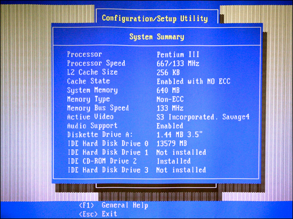
CMOS indicates the total amount of memory installed on the system. Typically, this entry is not modified unless you add or remove RAM and the change is detected on boot-up. If you do add or remove RAM from the system, the system detects the change and modifies CMOS for you. All you need to do is save the modification once in the CMOS setup program. Some systems today inform you that the system has saved the change for you and don’t require you to enter the CMOS setup program. Figure 4-7 shows the CMOS System Summary screen, which shows that there is 640MB of system memory installed on the system.
FIGURE 4-7: Viewing the amount of memory installed on the system through CMOS.
The CMOS in some systems not only tells you how much memory you have installed but also informs you of the type of memory that is installed. Here you should be able to see whether your system is using SDRAM, DDR, DDR2, or DDR3 memory. You should also be able to see the speed of that memory within CMOS.
CPU and clock speeds
CMOS displays system information such as the type of processor found on the system and contains detailed information about that processor such as the speed of the processor (clock speed) and the amount of cache memory present in the processor. You may have to view the system summary information to view the CPU speed.
Parallel port
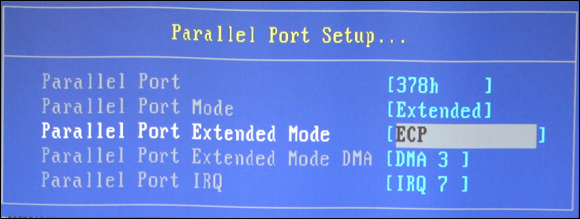
CMOS offers the opportunity to configure your parallel port. This configuration allows you to either disable the port or change the mode the port runs in.
You might think that a parallel port does not require a lot of configuration, but think about this: Have you ever had problems with a scanner that plugs into your parallel port? Or more specifically, have you ever had problems with your parallel-port scanner plugging into your computer and the printer then connecting to your scanner? The problems might derive from the parallel port mode being misconfigured on the system. The parallel port mode dictates the capabilities of the parallel port. Table 4-2 lists the three parallel port modes that can be configured for your system.
Supports communication in only one direction: from the computer to the device.
Enhanced Parallel Port (EPP)
2 MBps
A bidirectional port mode that enables communication in either direction: from the computer to the device and the device to the computer. This mode supports daisy-chaining.
Extended Capabilities Port (ECP)
More than 2 MBps
Supports bidirectional devices.
If you’re having trouble daisy-chaining the scanner and printer off the parallel port on the computer, check to make sure that the proper port mode is selected in the CMOS setup program (shown in Figure 4-8). In this example, you want to make sure that EPP is selected because it supports daisy-chaining.
FIGURE 4-8: Configuring the parallel port mode in CMOS.
Daisy-chaining is the feature of connecting one device off another, such as connecting the printer to the scanner and the scanner to the LPT (line print terminal) port.
The resources of the parallel port might also need to be configured if there are conflicts with another device. Notice that the default IRQ (interrupt request) for LPT1 is 7, and the default I/O address is 378-37F. You can read about IRQs and I/O addresses in Book 3, Chapter 4. For now, just make a mental note that you can configure the IRQ and I/O address of the parallel port in CMOS.
Serial ports
A typical system includes two serial ports — COM1 and COM2 — and CMOS should have an entry for each of the serial ports. These entries enable you to change the resources, such as the IRQ and I/O address used by each of the serial ports, as shown in Figure 4-9. The CMOS shown in Figure 4-9 identifies the two serial ports as serial port A and serial port B. For more information on IRQs and I/O addresses, see Book 3, Chapter 4.
Be sure to remember that the default IRQ for COM1 is 4, and the default IRQ for COM2 is 3. The default I/O address for COM1 is 3F8-3FF, and the default I/O address for COM2 is 2F8-2FF.
In the CMOS setup program, you can find not only an option to change the resources for the serial ports, but you can also disable the serial ports. Disabling the serial ports involves entering your CMOS program and switching a serial port to the disabled setting.
Date and time
The date and time each have an entry in CMOS as well, which is where the operating system (OS) gets its date and time information. Setting the date and time in CMOS sets the date and time for the OS. From a troubleshooting point of view, you know that your CMOS battery is dying when during startup, the system asks you for the date and time. During startup after a battery failure, all the other settings are detected again — which is why you don’t specify the hard disk or the floppy disk. However, the date and time must be specified again.
Boot sequence
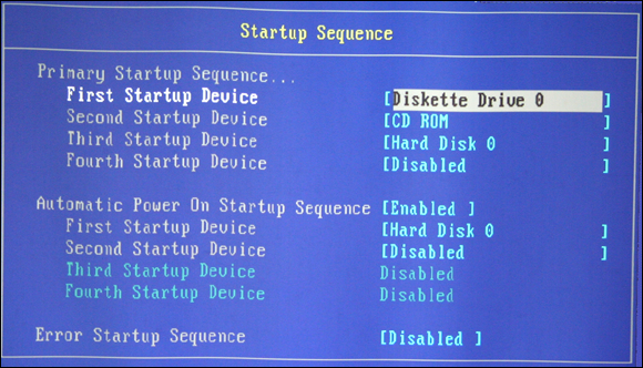
Take special note of the CMOS entry for boot sequence; it determines what devices the system will try to boot from and in what order it tries each device. For example, older systems are typically set up to boot off a floppy disk first; if a bootable floppy disk isn’t present, the system then boots off the hard drive.
Newer systems let you boot off a CD-ROM device or DVD, or even off the network first; and then, if no bootable device is found in either of those spots, proceed to boot off the hard drive. Booting off a CD-ROM or DVD device makes installing an OS extremely easy because most OSes today (like Windows or Linux) support booting off the installation CD to install the OS.
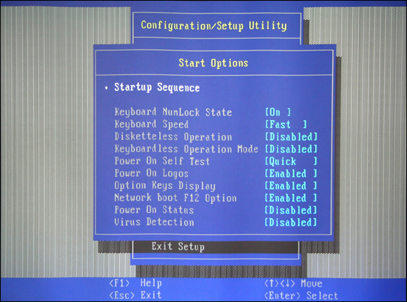
Most systems today are configured to try to boot from a floppy disk (if one exists), then a CD-ROM or DVD, then a hard disk, and finally a network. You determine the order to suit your needs, although typically, the floppy or CD-ROM drive is checked before the hard drive. If you like, you can disable devices, such as a CD-ROM drive, from being bootable. This is an important point because system security can be bypassed if a hacker can boot off his own CD containing his own copy of an OS. For security reasons, your company might consider disabling booting from floppy disk or CD-ROM. Figure 4-10 shows the CMOS menu where you can configure the startup order for your system’s devices.
FIGURE 4-10: Configuring the startup sequence in CMOS.
BIOS security features
In this section, you learn about some of the security features found in CMOS, which is also known in the objectives as BIOS security. In the BIOS security settings, you can configure password settings, encryption settings, and intrusion-detection settings on some systems.
User and administrator passwords
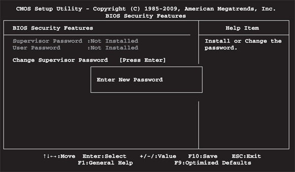
In general, two types of passwords can be set in CMOS: the power-on password (also known as a user password) and the administrator password. The steps to set the password are different per manufacturer, but you will usually find the password option under a security or advanced menu in the CMOS setup program.
The power-on password is required to power on the computer. It is part of the power-on process and occurs before the OS is loaded. Many people like to call it a hardware password because the OS (the software) won’t have a chance to load unless the correct password is entered. The implementation of power-on passwords can be especially useful in environments where security is a significant issue.
You set the administrator password in the CMOS setup program (shown in Figure 4-11). This password is required for anyone wishing to enter the CMOS setup program and make changes to the system configuration. It prevents unauthorized users from entering the CMOS setup program and changing the values that reside there.
FIGURE 4-11: Setting an administrator password in CMOS.
When people get comfortable with computers, they start to explore the computer’s options. Companies often end up spending time and money fixing problems that arise from the exploration of these options. This is why it might be useful to set an administrator password. The administrator password enables you to secure the workstation at the administrative level, and the power-on password allows you to secure the system at the user level — controlling who can use the system.
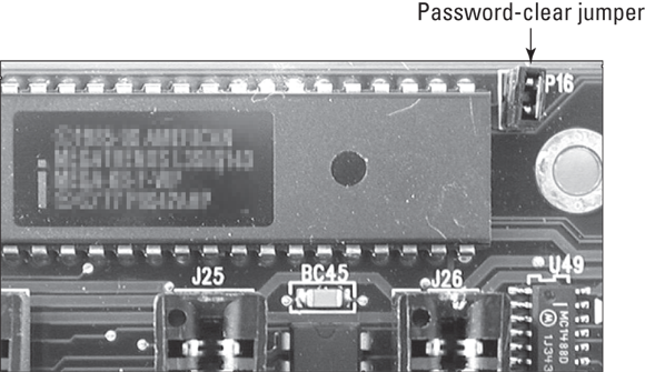
A question I often receive is, “What happens if you forget the CMOS password after it is set?” The answer is simple for desktops, but more difficult for laptops. First, check whether the motherboard has a jumper that can be removed to make CMOS forget the passwords (see Figure 4-12). After you remove the jumper to clear the password, put the jumper back on and power on the computer. Some systems have you place the jumper over specific pins in order to clear the password; check the documentation to find out how to clear the password for your particular system.
FIGURE 4-12: A jumper that can be removed to erase the CMOS password.
If no such feature exists on your motherboard, you could remove the CMOS battery from the motherboard. Remember that CMOS RAM retains its information because there is a battery supplying power to the memory where CMOS data is stored. If you remove the battery, CMOS is erased, including the passwords (which is better than throwing away the system).
The only problem with removing the battery is that all the CMOS information is lost, including your hard drive, memory, and other device settings. The good news is that most of the information should be detected again on startup, such as the amount of memory installed or the size of the hard drive.
Earlier in this chapter, I mention that if your system asks you for the date and time when it boots up, this is usually an indication that your CMOS battery is dead or dying. As noted here, the date and time aren’t the only things lost to a dying battery. If security is an issue and your system keeps asking you for the date and time at boot-up, replace the battery immediately and then reset the administrator password to keep others, malicious or benign, from altering the CMOS setup.
A third solution to a forgotten password — and the one I like — is to get a CMOS utility, such as the CMOS Save & Restore utility. CMOS Save & Restore backs up the CMOS information and then allows you to restore it when an emergency arises. This solution involves backing up CMOS before a password is set so that CMOS can be restored to a state without a password. These utilities are popular ones that can be found on the Internet, and they back up the CMOS information to a text file. An example of a CMOS save and restore program can be found at
Drive encryption is a sought after feature today by companies that have employees carrying around company data on mobile devices such as laptops. With many systems today you can encrypt the entire drive, or volume, of the system. Without the encryption keys, an unauthorized person cannot
View the contents of the drive or volume.
Boot a system from the drive or volume.
The following common technologies help protect a company's data on a mobile device:
TPM: The Trusted Platform Module (TPM) is a chip on the motherboard that can be used with full drive or volume encryption to store the keys used to encrypt the entire drive. In order to use TPM encryption, you must have a TPM chip on the motherboard, and a TPM-enabled BIOS.
Secure boot: Secure boot is a feature of UEFI systems that adds a layer of security to the boot process. During the boot process, only authorized software (that is, software that has a valid signature) is allowed to run. This includes core boot code for the operating system. When the system boots, the firmware checks the signatures. If they are valid, the operating system is allowed to boot.
LoJack: Another BIOS security–related technology that is available to laptops is LoJack. LoJack, created by a company called Absolute Software, is a feature that allows the laptop to connect to Absolute Software’s servers to specify the laptop location and verify if the laptop was reported stolen. This feature allows companies and law enforcement to track the location of stolen property. The LoJack feature is disabled by default and can be enabled on the laptop after purchasing a license key from Absolute Software.
Plug and Play BIOS
Most systems today have a Plug and Play BIOS (PnP BIOS). The term plug and play refers to the idea that you can connect a new device to the system, and the system automatically detects and configures the device to work with your system. To have a Plug and Play system, three conditions are necessary:
A Plug and Play device
A Plug and Play OS
A Plug and Play BIOS
If you are missing any one of these conditions, the OS cannot leverage Plug and Play and assign resources to a device on startup. On some older systems, you might see an entry in CMOS stating that it is a Plug and Play BIOS. All newer systems are Plug and Play BIOSes.
Viewing Advanced CMOS Settings
Many newer systems maintain the basic CMOS parameters mentioned in the previous section but are also supplemented by different advanced setup settings. This section examines the purposes and characteristics of some of these advanced settings.
Globally unique identifier (GUID)
The globally unique identifier (GUID) is a 128-bit number, randomly generated for the system when it was built, and stored in CMOS. The GUID uniquely identifies the system from any other. It enables the identification of individual computers and ensures that this identification method is absolutely unique.
Some systems have adopted the term UUID (universally unique identifier) instead of GUID. You might see a UUID in CMOS instead of a GUID, as shown in Figure 4-13, but they are the same thing.
FIGURE 4-13: Viewing the system UUID and BIOS revision number through CMOS.
BIOS date and revision number
The date of your BIOS should be displayed somewhere in CMOS, usually under Summary Information. If you don’t have a BIOS date, you might have a revision number or level. These entries in CMOS are important because you might be required to update your BIOS someday by going to the manufacturer’s website and downloading the update. The first thing you will notice when doing this is that the manufacturer has built many different versions of BIOS for its systems. You need to make sure you get the proper update (the one for the date of your BIOS) by watching the revision number of your BIOS. For example, the site might instruct you to download BIOS update 1234 if you have Revision number R5.145. The big question is how to know what your revision number is. Check CMOS! Refer again to Figure 4-13. You can see the BIOS version, or revision number, identified by the label Flash EEPROM Revision Level.
To ensure that you downloaded the correct BIOS update for the system, always make a note of the revision number and the date of the existing BIOS. Both pieces of information are typically used to determine which BIOS you need to download from the manufacturer’s website.
Universal Serial Bus (USB)
Universal Serial Bus (USB) devices have gained much recognition over the last decade. USB devices are high-speed serial devices that use a single connector style and can be chained together with a USB hub device. A USB hub device connects all USB devices together at a central point. The USB hub may be its own unique device, or it may be just another device in the USB chain that has the capability of connecting other USB devices to it. For example, a USB monitor may have a USB port to allow a mouse to connect to it. Some popular USB-type devices include digital cameras, scanners, mice, and keyboards. You can even find USB network adapters.
If you have any problems getting a USB device connected to your computer, make sure the USB port has been enabled in CMOS. Also, remember that you can disable the USB ports in CMOS (as shown in Figure 4-14) to help secure your environment. You might wish to do this to prevent a user on the network from using a flash drive to take home proprietary corporate data.
FIGURE 4-14: Disabling USB ports prevents using flash drives or other USB-type devices.
Built-in network adapter
Most systems today come with built-in network interface cards (NICs) that allow the system to connect to a network or the Internet. Because the card is built-in, you do not have to buy a network card for the system. However, built-in network cards (or any built-in device) sometimes become faulty, but your system does not know that and always tries to use this built-in device anyway. Note that you can usually enable or disable the built-in network card through the CMOS setup program.
When your system includes a built-in network adapter, you usually have the option of enabling or disabling the capability to boot off the network as well. Unless this option is enabled, you cannot boot off the network, even if you specified a network boot in your startup order.
You need to verify three options in CMOS in order to boot off the network: that the network card is enabled, that your system has enabled booting off the network adapter, and then that the network device is located in the startup order of devices. To boot off the network, you probably want the network as the first boot device.
In order to boot off the network, you need a Preboot Execution Environment (PXE)–compliant system. A PXE–compliant system is a system that has a BIOS that supports booting from a network card. For this to occur, you must ensure the network card is enabled and specified as a boot device within the CMOS setup. Once this is done, you can press F12 while the system is starting to boot off the network!
Virus protection
Some BIOS systems have built-in virus protection, which is (for the most part) a good thing. Some viruses attack the system by altering the Master Boot Record (MBR), which is the code that initiates the startup of the system and is located at the beginning of the hard drive. (For more information on MBR and hard drives, check out the next chapter in this minibook.) The virus protection built into the BIOS watches out solely for changes to the MBR and puts a stop to it!
Unfortunately, when you install a new OS, the installation modifies the MBR with its boot program files. As a result, the built-in virus detection in CMOS will see that “something” is modifying the MBR and will assume that it is a virus and stop the new OS from loading. In this case, you need to go into CMOS, disable the virus protection, and then restart the installation. After installation is complete, you will want to enable the virus protection in CMOS once again. Figure 4-15 shows the startup options that indicate that virus protection has been disabled.
FIGURE 4-15: Viewing the virus protection setting in CMOS.
Onboard cache
In Book 2, Chapter 3, I discuss the benefits of cache and the types of cache memory, L1 and L2. In CMOS, you typically find an entry indicating how much cache memory exists on the system, and you can configure CMOS to disable this built-in cache memory.
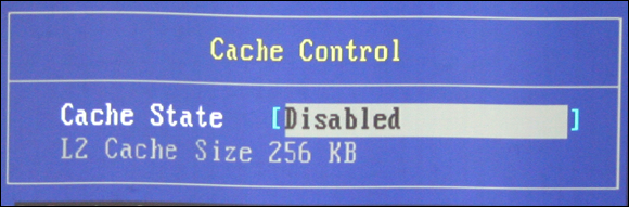
Sometimes cache memory goes bad and causes boot-up problems. If having cache memory enabled presents any compatibility problems with your system, you can try disabling the cache memory as a troubleshooting technique. Figure 4-16 shows the size of the cache memory and the option to enable or disable the cache memory. If the problem does not go away, there was no problem with the cache memory to begin with; enable the cache memory once again.
FIGURE 4-16: Disable built-in cache memory in CMOS to troubleshoot problems with corrupt cache memory.
Virtualization support
Virtualization technology is one of the hottest technologies to come out over the last decade. Virtualization allows you to run multiple operating systems in their own virtual machine (VM), on the same physical computer. Each virtual machine is assigned resources such as memory, disk space, and processor. The benefit of virtualization is that a company can now run multiple systems as virtual systems on one physical machine. This results in less power consumption and makes better use of the asset the company has purchased.
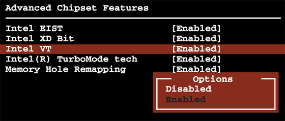
In order to support today's virtualization technology, you must enable virtualization support in the system BIOS. This enables the firmware on the physical computer (known as the host system) that creates virtual machines, and is known as the hypervisor. Figure 4-17 shows the display.
FIGURE 4-17: Enabling virtualization support in order to use VMs.
When looking to enable virtualization within the CMOS setup program, know that you are looking for one of two features. On Intel systems, you are looking for Intel Virtualization Technology (Intel VT) or AMD Virtualization (AMD-V) on AMD systems. Once you have located either of these settings, be sure to set the setting to enabled.
If you are purchasing a system that will run multiple VMs, ensure the system has a virtualization-supported BIOS before making the purchase.
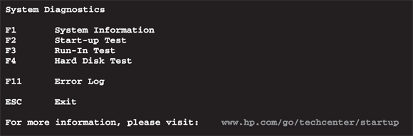
Built-in diagnostics and monitoring
Many systems today allow you to perform memory and/or hard drive diagnostics in order to identify problems with the systems that are due to memory issues or hard drive failure.
To perform the diagnostics, look for the diagnostics option in your CMOS and then choose the command to run the diagnostics. If there is a problem with memory or hard drive, the system will report a diagnostics failure.
Some BIOSes today also have monitoring features that can monitor the health of the system. For example, you may have a monitoring option that reports to you the temperature of the system or maybe the speed at which the drives are turning. Figure 4-18 shows the display.
Some examples of monitoring features that may be supported by your BIOS are:
Temperature monitoring: The BIOS may report through the CMOS program the temperature of components such as the CPU.
Fan speeds: The monitoring features of the BIOS may report to you the speed at which the fans are running, which directly relates to the temperature of the CPU.
Intrusion detection: The intrusion detection monitoring will let you know if the computer case has been opened, keeping you aware of potential theft of components such as RAM or the hard disk from the computer.
Voltage: The monitoring features may report to you the voltage amounts being utilized by different components such as the CPU.
Clock: The clock speed may be reported indicating the speed of the CPU.
Bus speed: The monitoring feature may also report to you the speed of the different buses within the system.
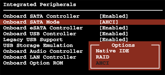
AHCI settings
The Advanced Host Controller Interface (AHCI) is a standard developed by Intel that allows software to communicate with SATA devices and take advantage of SATA features such as hot-swapping. Many system BIOSes today allow you to specify the operation mode of SATA through the AHCI mode in the BIOS settings.
With most systems today, you can configure the AHCI mode (see Figure 4-19) to any of the following:
PATA Emulation: Also known as IDE compatibility mode or ACPI, this mode emulates IDE and should be used if you are installing an older operating system, such as Windows XP, that does not have SATA drivers for your drive.
AHCI Mode: Enables SATA mode and should be used to gain the performance benefits of SATA if your operating system has a SATA driver. If the installation of the operating system does not detect the drive, try switching to IDE compatibility mode.
RAID: Used to support SATA in a RAID configuration.
If you are supporting older systems, you can reserve resources that have been assigned to legacy devices in CMOS. Legacy devices are non–Plug and Play devices, such as ISA (Industry Standard Architecture) cards, that have been added to the system. The ISA non–Plug and Play devices are hard-coded with a particular I/O address and IRQ, so you might need to configure CMOS to reserve the IRQ so that it is not given to a Plug and Play device on startup.
Removing the IRQ will ensure that a Plug and Play system will not assign the resources that are hard-coded into older devices to Plug and Play devices, which would create a conflict. Most systems today are Plug and Play, so unless you are supporting older hardware, you will most likely not hit this issue.
Now it is time to get some hands-on experience by performing Lab 4-1 and Lab 4-2. Lab 4-1 and Lab 4-2 can be downloaded from the companion website at www.dummies.com/go/aplusaio.
Getting an A+
In this chapter, you have learned about some of the common settings found in CMOS setup of systems today. You discovered the basic and advanced parameters in CMOS. The following points are covered:
The BIOS is low-level code used by the system to communicate with the system hardware. The BIOS code is stored on an EEPROM chip located on the motherboard of the system.
The BIOS is typically updated by downloading a BIOS update program and “flashing” the BIOS.
You enter a system’s CMOS setup program by using a keystroke such as F1 (IBM), F2 (Dell), or Delete when the system starts up.
You can change the boot order of the different bootable devices.
The three parallel port modes are SPP, EPP, and ECP.
You can change the hard drive from autodetect to manual so you can input the drive dimensions.
In order to support virtualization technology, you must have enabled virtualization support in the BIOS.
You can update your BIOS by downloading the BIOS update for your system from the BIOS manufacturer’s website.
Prep Test
1.You have a USB camera from which you are trying to copy some of the pictures to the computer’s hard drive. The computer does not seem to recognize the device. What should you do?
(A) Check to see that the boot order is correct.
(B) Make sure that the USB ports are enabled.
(C) Make sure that the serial port is enabled.
(D) Make sure that the operating system has not assigned the USB device resources to some other device.
2.You are part of the help desk support team for your company. One of your users calls complaining that the computer constantly prompts for the date and time. What does this indicate?
(A) The date and time are wrong.
(B) The time has fallen back by one hour.
(C) The battery on the motherboard is losing its charge.
(D) The time has increased by one hour.
3.You are installing Windows on a newer system with SATA drives, but the Windows setup program does not detect the drive. What should you do?
(A) Replace the BIOS with a non–Plug and Play BIOS.
(B) Enable the AHCI IDE Compatibility option in CMOS.
(C) Install an IDE drive.
(D) Enable the AHCI RAID option in CMOS.
4.Your manager is worried that someone will be able to start up any of the computers and view confidential information. What could you do to ensure that anyone starting the computer is supposed to be using that system?
(A) Lock the computer case.
(B) Set file-share permissions on the files that are confidential.
(C) Set a power-on password in CMOS.
(D) Use NTFS permissions to protect the files from unauthorized access.
5.You are installing Windows on your computer, and you know that the Windows CD is a bootable CD. You have tried a number of times to boot off the CD, but you are unable to. What CMOS option should you look for?
(A) You must delete the existing partitions so that you can boot off the CD-ROM.
(B) Ensure that the CD-ROM device has been set up as the first device in the startup (boot-up) order.
(C) Disable the hard drive in CMOS.
(D) Disable the CD-ROM in CMOS.
6.You are worried that some of your advanced computer users on the network will start changing the settings within CMOS. What is the best thing you can do to protect these settings?
(A) Set a power-on password.
(B) Set an administrator password.
(C) Set a Windows log-on password.
(D) Ask the advanced users not to change any of the CMOS settings.
7.Your built-in network adapter doesn’t seem to be connecting you to the network. What is one of the first things you want to check for in CMOS?
(A) That the built-in network adapter is enabled in CMOS
(B) That the network adapter driver is loaded
(C) That the resources are not conflicting
(D) That the proper protocol is installed
8.You are trying to boot the system off the network, but the computer doesn’t seem to boot off the network adapter. You have verified that the network adapter has been enabled in CMOS. What else should you check for within CMOS?
(A) That the network card has been disabled
(B) That the network adapter has been disabled
(C) That the CD-ROM has been configured as a bootable device
(D) That the network adapter is set up as a bootable device
9.You are experiencing a lot of problems running your customized software on some of the newer computers. What might you try disabling in CMOS to clear up the compatibility issue between the software and the system?
(A) RAM
(B) Cache memory
(C) Hard drive
(D) Floppy drive
10.You are having trouble installing a new operating system on your computer because the installation fails with each attempt. Which of the following CMOS settings would you disable to help the system make it through the installation?
(A) Network adapter
(B) Bootable CD-ROM
(C) Antivirus
(D) Bootable network adapter
11.Which of the following is a typical method for updating your system BIOS?
(A) Replace the old BIOS chip with a new BIOS chip.
(B) Run a BIOS update program, also known as firmware upgrade, that flashes the BIOS with a new version of the BIOS.
(C) Replace the old motherboard with a new one.
(D) You cannot update the BIOS.
12.Which of the following best describes the difference between BIOS and CMOS?
(A) BIOS contains the configuration information for the system, and CMOS is the low-level code that allows the devices to communicate.
(B) BIOS is stored in RAM, and CMOS is stored in ROM.
(C) BIOS is stored in RAM, and CMOS is stored in cache memory.
(D) CMOS contains the configuration information for the system, and BIOS is the low-level code that allows the devices to communicate.
Answers
B. In today’s systems, many of the built-in devices can be enabled or disabled in the CMOS setup program. When experiencing problems with a built-in device, the first thing you should check is whether the device is enabled. See “Built-in network adapter.”
C. The CMOS configuration information is stored in CMOS RAM. This special RAM chip maintains its information by using a small battery on the system board. If the battery loses its charge, the CMOS RAM is flushed out, meaning that it will prompt you for the information such as the date and time as the system boots up. Review “Date and time.”
B. The newer CMOS setup programs allow you to change the configuration so that the SATA is emulating an IDE interface. This can allow software that is not SATA aware to recognize the drive. Check out “AHCI settings.”
C. Choice C is the best answer to ensure that only authorized individuals are powering on the system. In order to use the system, someone will need to type the CMOS password. This password is not dependent upon any particular operating system because you are setting a hardware-level password. Peruse “User and administrator passwords.”
B. Many computers are set up to boot off the floppy drive, then the hard drive, and finally the CD-ROM, which means that if the system can boot off the floppy or hard drive, the opportunity will never arise to boot off the CD-ROM. Changing the startup order so that the CD-ROM is the first bootable device means that you can put in the Windows CD-ROM, and setup will be invoked from it. Choice A would work, assuming that the CD-ROM device is listed anywhere in the bootable device order. Unfortunately, you have lost the contents of the hard drive because partitions have been wiped out, so Choice A is not the best answer. Take a look at “Boot sequence.”
B. An administrator password is a password that must be provided to enter the CMOS setup program and change the settings. Choice A is not the right answer because you might not want to set up a password for when the computer turns on but only if a user tries to enter the CMOS setup program. Peek at “User and administrator passwords.”
A. One of the first things you want to do with a built-in device is ensure that the device has not been disabled in CMOS. If it has not been disabled, you should look at the other choices for the solution. Study “Built-in network adapter.”
D. When booting the system from the network, you need to ensure that the computer not only has the network adapter enabled, but also that the network adapter is signified as a bootable device, and maybe even the first bootable device. In this question, you have already verified that the network adapter has been enabled, so Choice D is the only possible answer. Refer to “Built-in network adapter.”
B. Many systems today have built-in cache memory. Although it isn’t that common, you might sometimes have problems with particular software not “liking the idea” of using information from cache instead of RAM. To test this, temporarily disable the cache memory. Examine “Onboard cache.”
C. Viruses commonly attack the MBR of the hard drive, so virus software constantly watches out for applications that try to make a change to this area of the disk. Some systems today have built-in virus detection, and because the installation of a new operating system causes a change to the MBR, there may be incompatibilities between the OS installation and the virus protection built into the system. Disabling this virus protection in the CMOS will allow the installation to finish. See “Virus protection.”
B. To update your BIOS today, you will download the update from the Internet and then run the update. In the past, you would have to replace the entire ROM chip. Review “Performing the BIOS upgrade.”
D. CMOS is the inventory list of devices and their configuration, whereas the BIOS is the set of low-level instructions that tells these devices how to communicate. Choice B and Choice C are wrong because BIOS code is stored in ROM, not RAM. Check out “BIOS versus CMOS.”
 BIOS — basic input-output system — is the low-level instructions the system uses to communicate with the system devices. This is different than CMOS (complementary metal-oxide semiconductor), which is simply an inventory list of the configuration information for the system, containing information such as the hard drive space and amount of memory that exists on the system. Keep this in mind:
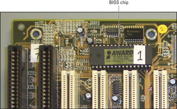
 Installing the wrong BIOS version can cause the system to become dysfunctional. If you can’t find a BIOS version number, use the BIOS date to decide which update to download. The current BIOS version or date can be located within CMOS or seen with the BIOS manufacturer on the screen during boot-up, as shown in
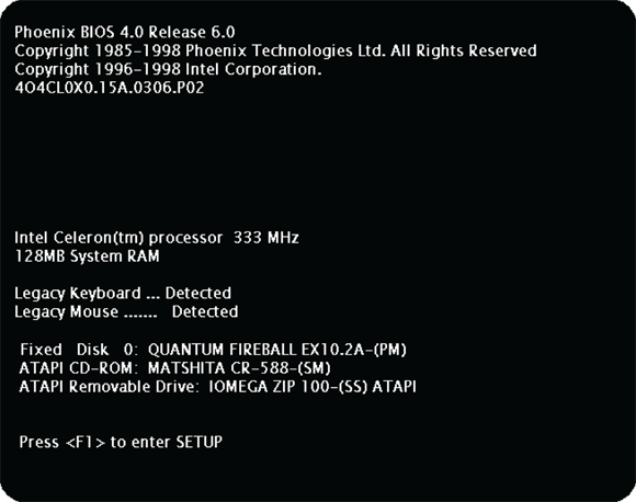
 As a way to prevent accidental writing to the BIOS code, some motherboards ship with a jumper on the board that must be removed to write to the BIOS chip. When you want to upgrade the BIOS and you have the correct BIOS update, you remove the jumper and then run the BIOS update. After updating the BIOS, you place the jumper back.


 Daisy-chaining is the feature of connecting one device off another, such as connecting the printer to the scanner and the scanner to the LPT (line print terminal) port.
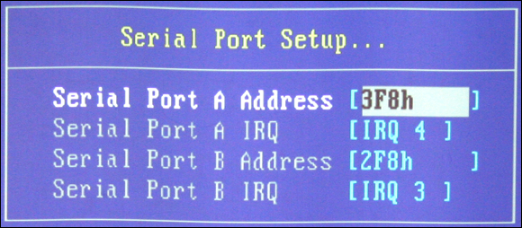


 Now it is time to get some hands-on experience by performing Lab 4-1 and Lab 4-2. Lab 4-1 and Lab 4-2 can be downloaded from the companion website at