Chapter 3. Site-to-Site VPNs
This chapter covers the following subjects:
• Site-to-Site VPN Architecture: This section describes how to develop a plan to build a site-to-site VPN architecture.
• Site-to-Site Components: This section provides a short review of the key components needed for a site-to-site VPN.
• VPN Tunnel Concepts: This section provides an overview of foundational VPN tunnel concepts.
• Router Configuration with IKEv1: This section describes how to develop a plan for and configure a basic IKEv1-based site-to-site VPN.
• Router Configuration with IKEv2: This section describes how to develop a plan for and configure a basic IKEv2-based site-to-site VPN.
• Appliance Configuration: This section describes how to develop a plan for and configure site-to-site VPNs for different Cisco security appliance options.
• High Availability: This section provides a review of the high availability options with Cisco site-to-site VPN technology.
“Invisible threads are the strongest ties.”
—Friedrich Nietzsche
This chapter covers the following exam objectives:
• 1.0 Site-to-site Virtual Private Networks on Routers and Firewalls
• 1.1 Describe GETVPN
• 1.2 Describe DMVPN
• 1.3 Describe FlexVPN
• 4.0 Secure Communications Architectures
• 4.1 Describe functional components of GETVPN, FlexVPN, DMVPN, and IPsec for site-to-site VPN solutions
• 4.3 Recognize VPN technology based on configuration output for site-to-site VPN solutions
• 4.6 Design site-to-site VPN solutions
• 4.6.a VPN technology considerations based on functional requirements
• 4.7 Design remote access VPN solutions
• 4.7.a VPN technology considerations based on functional requirements
• 4.7.b High availability considerations
Companies that are successful are likely to grow in size. Growth can occur by hiring more people, partnering with other businesses, or merging or acquiring another organization. As growth occurs, there is likely to be a point where resources need to be shared between different parts of the organization over untrusted mediums like the Internet. This is where site-to-site VPN technology can come to the rescue.
Site-to-site VPN technology can provide a lot of functionality and financial value. The most obvious value is allowing one or more trusted locations to communicate across an untrusted medium. However, connecting one or more resources over an untrusted medium isn’t as simple as providing full access to anything for anybody. Opening up that level of access could lead to unauthorized data access. Different levels of access need to be granted based on business requirements and security policies. A properly designed and implemented site-to-site VPN architecture balances ease of accessing resources and granting access to only what is required. A best practice for data access control is to provide access to only what is needed; this is called “least privilege access.”
Conceptionally, least privilege access sounds simple, but in practice, it can be extremely complex. As an example, a site-to-site VPN might need to support users with multiple job roles, accessing resources from different locations and from multiple different device types. We teach you not only how to connect different locations using site-to-site VPN technology but also look at how to choose and enforce the right security controls within the access you provide. Such skills are required to properly deliver site-to-site VPN services and to pass the SVPN 300-730 exam.
This chapter explores site-to-site VPN technology. The goal is to address various site-to-site architectures and features so you can adjust your design to meet both your business and security needs. You will find that there are many options available in modern VPN technology, including different levels of encryption, hardware, and software, as well as various levels of effort required to set up, maintain, and troubleshoot different site-to-site VPN options. We cover all of this over the next few chapters to prepare you for real-world deployments as well as the SVPN 300-730 exam.
Learning beyond the SVPN concepts:
• Site-to-site VPN Architecture and Design Considerations
• Appliance Configuration – Cisco Secure Firewall and Cisco Meraki
“Do I Know This Already?” Quiz
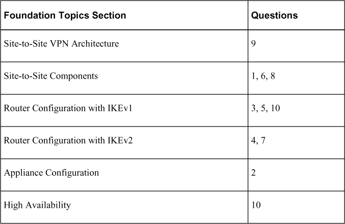
The “Do I Know This Already?” quiz enables you to assess whether you should read this entire chapter thoroughly or jump to the “Exam Preparation Tasks” section. If you are in doubt about your answers to these questions or your own assessment of your knowledge of the topics, read the entire chapter. Table 3-1 lists the major headings in this chapter and their corresponding “Do I Know This Already?” quiz questions. You can find the answers in Appendix A, “Answers to the ‘Do I Know This Already?’ Quizzes.”
Table 3-1 “Do I Know This Already?” Foundation Topics Section-to-Question Mapping
1. Which of the following mechanisms are found within IPsec? (Choose two.)
a. SHA
b. AH
c. ESP
d. TTL
2. What is the command-line command on an ASA running Version 8.4 or greater to create a IKEv1 policy?
a. crypto ikev1 policy 1
b. crypto isakmp policy 1
c. crypto pki ikev1
d. ikev1 crypto 1
3. Which of the following occurs during phase 2 of the IKE key exchange?
a. IKE policy negotiation
b. IPsec SA exchange
c. Authentication
d. Diffie-Hellman (temporal keys)
4. Which of the following is a characteristic of IKEv2?
a. Public key encryption is used for authentication.
b. Both peers must use the same authentication.
c. NAT is supported by default
d. Multi-hosting is not supported.
e. None of these options are correct.
5. Which of the following are possible authentication methods for IKE? (Choose all that apply.)
a. RSA signature method
b. RSA encrypted nonces method
c. Pre-shared keys
d. Public and private key
6. Which of the following are the primary components of a VPN tunnel? (Choose three.)
a. A transport protocol
b. An initiation protocol
c. A carrier protocol
d. A passenger protocol acting as the protocol that is being encapsulated.
7. True or false: With IKEv2, both peers use the same authentication.
a. True
b. False
8. What is the purpose of digital certificates? (Choose two.)
a. Authenticating websites, people, and devices
b. Holding identity credentials
c. Authorizing systems
d. Validating authorized systems
9. Which of the following is the least important question to ask when planning a site-to-site VPN project?
a. How much is the up-front technology?
b. Does an industry analyst show this technology as best of breed?
c. Who can you call for support, and what does support cost?
d. Is the technology being used close to end of sale/end of support?
10. Which of the following is not a site-to-site VPN high availability option?
a. Hot standby
b. Cold standby
c. Active/standby
d. Active/active
Foundation Topics
We kick off this part of the book with a focus on site-to-site VPN concepts, which is the first of two VPN technology categories you need to know for the SVPN exam. This chapter serves as a primer for Chapters 4 through 6 and covers the foundational concepts behind site-to-site VPN technology. The remaining part of the book focuses on remote access VPN.
Why care about site-to-site VPN technology? Besides knowing it is a requirement for the SVPN exam, you should care about this topic based on how widely used it is within all types of organizations around the world. The Internet is a dangerous place, and security needs to be applied between locations looking to share data. Many common threats such as data loss, breach of data confidentiality, and modification of data can be avoided by implementing a strong site-to-site VPN architecture.
Different flavors of site-to-site VPN technologies are available when using Cisco security appliances. The SVPN exam specifically calls out requirements for knowing how to identify, deploy, and troubleshoot GETVPN, DMVPN, and FlexVPN. The next three chapters focus specifically on these topics. Before moving to those chapters though, make sure you master the foundational concepts covered in this chapter.
Site-to-Site VPN Architecture
As mentioned in Chapter 2, “Introduction to Virtual Private Networks (VPNs),” a site-to-site VPN is a VPN that connects different locations over untrusted networks. Chapter 2 provides a handful of site-to-site design examples, including hub-and-spoke, spoke-to-spoke, full mesh, and hybrid VPNs. Which approach is right for your organization? What technologies and configurations are involved with a site-to-site VPN? This chapter begins to answer these questions.
Site-to-Site Design Considerations
The first place to start when deciding which approach to use for a site-to-site VPN project is to review the project at a high level. This is where we start when we consult with customers. Many times, particular design elements or available equipment quickly narrows down the possible options for the project. It is important to consider the following when collecting high-level information about a potential project:
• What is the budget?
• What technology is available for the VPN project?
• What is your expected future growth?
• What is the current traffic on the network?
• How many sites are part of the design?
• What are your high availability and network resilience requirements?
• What existing skill sets and technology familiarity do you have in your organization?
• What are your in-house versus external management expectations for the solution?
• What compliance requirements do you need to keep in mind?
When we consult with customers on choosing the right site-to-site VPN for a project, the answers to these questions lead us to the options that could work, based on the customer’s design needs. The available budget will impact factors such as how much redundancy and which features are within reason. The available technology is extremely important because many customers already have tools that can be used in a VPN, such as their existing routers or firewalls, but they need to configure the equipment or purchase additional licensing. Compliance and technical requirements obviously narrow down the design, and we find that such requirements may be adjusted based on the technology and budget available. Existing skill sets and technology familiarity will also influence the design; for example, if the organization has always used Cisco equipment, they will likely want to continue to use Cisco equipment. Most engineers would rather work with technology they are familiar with than learn a whole new vendor’s way of configuring and managing technology.
Scoping a Project
When scoping a site-to-site VPN project, it is very important to consider the full life cycle of the project. Sometimes vendors and service providers offer free hardware, software, or services up front but force the use of additional hardware, software, or services after their technology is initially implemented as a way to make a sale. In such cases, the full deployment of a solution might end up actually costing more than other options and provide fewer features and less support. To avoid such a pitfall, consider the following aspects of the life cycle of your VPN project:
• How much does the upfront technology cost?
• What additional technology will be needed during the life cycle of the project?
• What services are required to install the entire solution properly?
• Are any additional services left out of the scope (for example, deploying software to each endpoint, upgrading existing systems, technology training)?
• Is the technology close to end of sale/end of support?
• Who can you call for support? Is there a cost for that?
• How reputable are the technology and the company?
It is ideal to use this list when planning any request for technology and services.
Once you have scoped out the high-level design of a VPN project, the next step is to fill in the details to make it all work, starting with choosing the components to use.
Site-to-Site Components
A variety of technology components are involved with a site-to-site VPN. You will find that some elements are required for a site-to-site VPN regardless of the approach used, while others depend on the approach and vendor of choice. An important factor in deciding which VPN technology to use is available technology; it is a good idea to leverage existing investments whenever possible.
Routers vs. Security Appliances
An important aspect to consider is the hardware or software that will provide the VPN service. From a high level, we can simply break this down into two categories: routers and security appliances.
Chapter 2 summarizes the different VPN types and the Cisco technologies that support VPNs. Cisco routers (or IOS-based VPNs) have options such as GETVPN, DMVPN, GRE-based VPN, and FlexVPN. None of these options, however, are supported on a Cisco security appliance such as the Cisco ASA. This means if routers are being used for a site-to-site VPN, you are likely going to have more design options than if you use security appliances. You also need to validate the models of hardware used and confirm the versions of code being used; different models of hardware support different numbers of VPN sessions, and different versions of code support different VPN options. Cisco routers that support site-to-site VPNs typically run IOS or IOS XE. This includes CSR Series and ASR 1000 Series routers.
Note
Most Cisco routers do not require additional licenses to support a basic IPsec site-to-site VPN. You should validate your project’s scope using the data sheet for the Cisco router to confirm any licensing requirements before proceeding with a project.
Cisco Security Appliances for Site-to-Site VPNs
Cisco security appliances also offer site-to-site VPN functionality. The hardware limitations and license options for such an appliance determine whether and how many VPN sessions are supported. The hardware limitations can be found by looking at the model’s data sheet. Keep in mind that certain licensing may be required to be installed before a VPN can be configured. The following Cisco security appliances support site-to-site VPN functionality:
• Cisco Adaptive Security Appliance (ASA) Series
• Cisco Secure Firewall Series
• Cisco Meraki MX Series
Note
For the SVPN 300-730 exam, you are likely to only be tested on the command line and GUI for the Cisco ASA Series.
IPsec
An important consideration with VPN technology is how data is protected by the VPN. IP Security (IPsec) is a popular option to use when choosing how a VPN will function. Basically, IPsec is a framework of related protocols used to secure communication at the network layer. The IPsec framework is made up of open standards developed by the Internet Engineering Task Force (IETF) that are designed to offer data confidentiality, data integrity, and data authentication between participating peers. IPsec accomplishes these goals by providing authentication, encryption of IP network packets, key exchange, and key management.
Authentication Header
IPsec originally defined two options for imposing security on IP packets. The first mechanism, Authentication Header (AH), is a protocol defined in RFC 4302 that specifies a method for digitally signing IP packets. Signing packets is accomplished by hashing the IP header and data payload. Using this hash, a new AH header is built, and it is then prepended to the packet. Think of this new header as a digital validation that the data has not been changed. A hash (for example, MD5 or SHA) is a generated number that can be reproduced to validate the source; a different value is generated if any change occurs in what is being hashed. Even a change in a single bit will generate a new hash, indicating that a change has been made. This newly created packet is transmitted via normal routing means until it reaches the destination IPsec peer, where the AH header is removed, validated and the original payload is sent on its destination. AH also includes replay protection, using a Sequence Number field within the AH header. This replay protection excludes fields that are expected to change, such as the Time-to-Live (TTL) field.
Note
Authentication Header (AH) is used to digitally sign data to ensure that it hasn’t been modified (providing data integrity, data origin authentication, and replay protection). This means AH provides a mechanism for authentication; the actual data inside the packet is not encrypted. AH isn’t used much in today’s networks.
Encapsulating Security Payload
The second original IPsec mechanism is the Encapsulating Security Payload (ESP) protocol, defined in RFC 4303, which is used to encrypt data and ensure the integrity of data packets. ESP uses the same algorithms as AH; however, it provides coverage differently from AH. ESP is added after the standard IP header, and it is important to point out that this means it contains the standard IP header. This is important because it allows easy routing of traffic with standard IP devices. It also makes IPsec backward compatible with IP routers and devices that were not designed to function with IPsec. ESP operates at the network layer and can be viewed as containing several parts. Security Parameter Index and Sequence Number are only authenticated but not encrypted. The remaining four parts—Payload Data, Padding, Pad Length, and Next Header—are all encrypted during transmission. ESP supports multiple encryption protocols which you can choose to enable or opt out of.
Note
ESP provides encryption (data confidentiality) and authentication (data integrity, data origin authentication, and replay protection). ESP can be used only for encryption, only for authentication, or for both.
Comparing AH and ESP
It is important to understand the difference between ESP and AH and why this difference exists. AH authenticates an entire IP packet, including the outer packet. ESP authenticates only the IP datagram portion of the IP packet. If you do not want to expose any part of the outer packet for security reasons, you might want to use AH; if you want ease of routing, you might consider ESP the best option. With either AH or ESP, you need to choose the algorithm used to encode authentication data in the AH or ESP headers.
Note
Expect the SVPN 300-730 exam to challenge your understanding of the differences between ESP and AH.
Figure 3-1 shows an example of AH and ESP when used in transport mode and tunnel mode. We cover transport and tunnel mode concepts later in this chapter.


Figure 3-1 AH and ESP in Transport Mode and Tunnel Mode
ISAKMP
To support IPsec, the Internet Key Exchange (IKE) protocol (RFC 7296) was added to specify which services are to be incorporated in packets, which cryptographic algorithms will be used to provide those services, and a mechanism for sharing keys used with those cryptographic algorithms. Internet Security Association and Key Management Protocol (ISAKMP) is now also specified as part of the IKE protocol suite. ISAKMP defines how security associations (SAs) are set up and used to define direct connections between two hosts that are using IPsec. A security association includes all relevant attributes of the connection, including the cryptographic algorithm used, the IPsec mode, the encryption key, and other parameters related to the transmission of data over the VPN connection. ISAKMP traffic functions on UDP port 500.
Many other protocols and algorithms use or are used by IPsec, including encryption and digital signature algorithms, which you can learn more about by reviewing RFC 6071. Keep in mind that if you are looking to permit IPsec traffic, you will likely need to permit UDP port 500 for ISAKMP, IP protocol 50 for ESP, and IP protocol 51 for AH traffic. Also know that IPsec could be configured without using IKE; however, IKE enhances IPsec by providing additional features, flexibility, and simplification of configuration for the IPsec standards, including keepalives. GRE keepalives are essential for network resilience because the heartbeat must be maintained to avoid unwanted failover. We cover failover concepts later in this chapter.
Note
Make sure to understand the components of IPsec, including which ports and protocols are used as well as their role in VPN technologies.
IKE Security Association
We stated that IKE handles the negotiation of the SA, which, simply put, is the process of establishing security attributes between two network entities trying to build the site-to-site VPN. This explains how VPN peers exchange certain information, including information on protecting negotiation, establishing a shared secret over an insecure medium, and authenticating each peer.
Figure 3-2 provides a visual of this process to help you understand IKE. Phase 1 is the IKE negotiation. Phase 2 is the SA exchange. Finally, if everything works, data is sent.
Figure 3-2 IKE Data Flow Diagram
IKE Version 1 and 2
There are currently two versions of IKE: Version 1 (IKEv1) and Version 2 (IKEv2). IKEv1 (released in 1998 and described in RFC 2409) is the older version and is still used today; however, it has been declared obsolete by the IETF. Cisco and Microsoft worked together to develop IKEv2, which was released in 2005 and described in RFC 4306. IKEv2 is a low-latency alternative to IKEv1 with the data format ISAKMP.
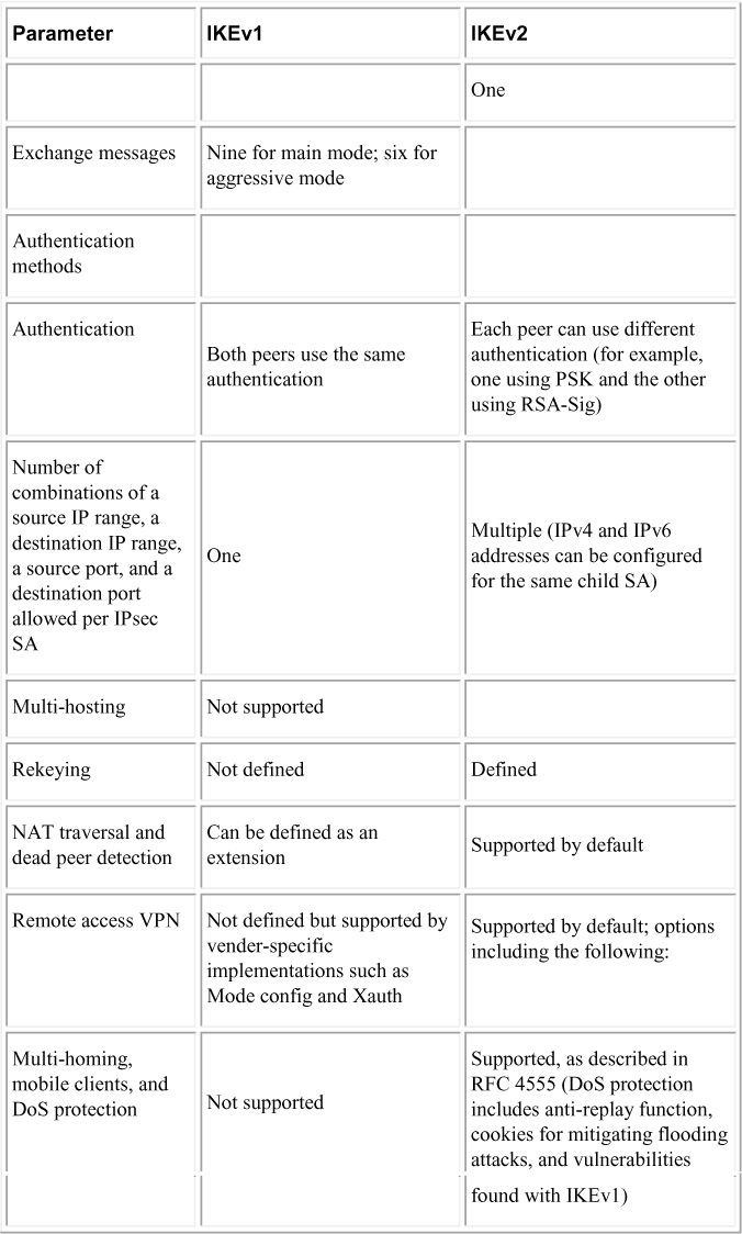
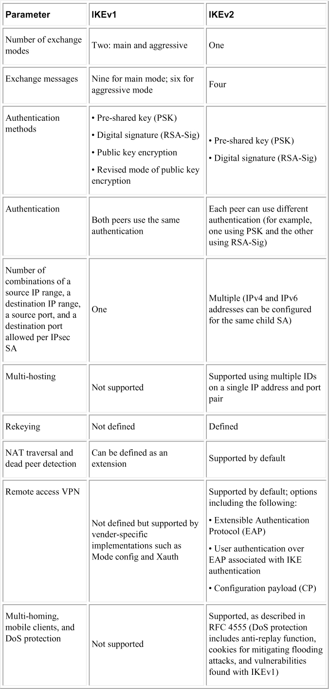
The biggest difference between IKEv1 and IKEv2 is that IKEv2 is much simpler and more reliable than IKEv1 because fewer messages are exchanged during the establishment of the VPN, additional security capabilities are available, and there is support for mobile devices. IKEv2 supports mobile devices with its resilience to network changes. Table 3-2 compares IKEv1 and IKEv2.
Note
Make sure you understand the fundamentals of IKEv1 and IKEv2 for the SVPN 300-730 exam.
Table 3-2 Comparison of IKEv1 and IKEv2

Key IKE Concepts
Make sure you know the following general IKE concepts for the SVPN 300-730 exam:
• IKE is based on the following underlying security protocols: ISAKMP, SKEME, and OAKLEY.
• IKEv2 supports AES, 3DES, Camellia, ChaCha20, and PFS+. (It also supports MOBIKE for network changes.)
• IKEv2 offers support for remote access by default, thanks to the use of EAP authentication.
• IKEv2 consumes less bandwidth than IKEv1.
• IKEv2 is resistant to network changes and is ideal for mobile devices, thanks to MOBIKE support.
• IKEv2 has built-in NAT traversal, unlike IKEv1, which must be explicitly configured.
• IKEv2 supports more algorithms than IKEv1.
• IKEv2 is more resistant to DoS attacks than IKEv1 because IKEv2 first determines whether the requestor actually exists.
• IKEv2 only uses UDP port 500, which can be blocked by a firewall or network tool.
Note
Avoid using weak pre-shared keys when using IKE. IKE is used to establish the shared secret for an IPsec connection. Both IKEv1 and IKEv2 could be vulnerable to Bleichenbacher’s Oracle treat if weak pre-shared keys are used. Learn more about this potential vulnerability at https://www.usenix.org/system/files/conference/usenixsecurity18/sec18-felsch.pdf. Security patches that address this threat are related to vulnerability CVE-2018-0131.
IKE Authentication
In Table 3-2, you can see that different authentication options can be used as you configure IKE. Those options impact the additional steps you need to perform in order to properly configure an IKE policy on a Cisco device. IKEv1 has four different options, and IKEv2 has two. The following are all the different authentication methods and the expected additional configuration required in an IKE policy:
• RSA signature method (rsa-sig): If you use RSA signatures as the authentication method in your IKE policy, you will likely configure all peers to obtain certificates from a certificate authority (CA), which are covered shortly. The certificates are used by each peer to securely exchange public keys. Both peers show valid certificates and automatically exchange public keys as part of any IKE negotiation using RSA signatures.
• RSA encrypted nonces method (rsa-encr): If the RSA encrypted nonces method is used in your IKE policy, you need to make sure each peer has the other peer’s public keys. To be clear, rsa-encr does not use certificates like RSA signatures. Instead, a public/private key exchange process is used. A hybrid approach could also be used; in such a case, the initial connection would use RSA signatures to share keys, and then all future exchanges could use the RSA encrypted nonces method. This hybrid approach would require both the RSA signature and RSA encrypted nonces policies to be configure, and the RSA signature policy would have a lower priority. Any failure in rsa-encr would fall back to the rsa-sig policy. Remember that if the rsa-sig policy is also being used, you need to have a CA configured.
• Pre-shared keys (pre-share): If pre-shared keys are used, you need pre-shared keys to be shared between peers. You learn more about this in the IKE configuration examples later in this chapter.
• Digital certificates: If you used digital certificates as the authentication method in an IKE policy, a CA must be set up to issue digital certificates. This approach simplifies authentication because you only need to enroll each peer with the CA rather than manually configure each peer to exchange keys, as in the RSA approach. If you have a larger network, it is highly recommended that you use the digital certificate approach. Cisco devices treat RSA signatures and digital certificates similarly in terms of configuration.
Note
There are differences between a digital signature (rsa-sig) and a digital certificate. A digital signature is used to verify that a document, message, or transaction is authentic—that is, the message was actually generated by the sender and not modified by a third party. Think of this as not only signing the document but proving that the message being sent is accurate, validating that the message hasn’t been tampered with, and providing nonrepudiation, meaning the sender can’t deny having sent the message.
A digital certificate is similar to an identification card such as a passport or driver’s license. Digital certificates are issued by a recognized authority and are used to validate the identity of the user or device presenting the certificate. You should expect to see SVPN 300-730 questions that challenge your understanding of these two concepts.
Later in this chapter you will see how to configure a few site-to-site VPN design examples. If you look back at Table 3-2, you will notice that IKEv2 only offers digital certificates and RSA-sig for authentication, and IKEv1 offers all four authentication methods.
VPN Tunnel Concepts
Part of creating a VPN is establishing an encrypted connection between two or more networks. Encrypting a connection means using a tunnel to encapsulate packets inside a transport protocol. Tunneling has three primary components:
• Passenger protocol: This protocol is the protocol that is encapsulated. Examples of passenger protocols include IP, AppleTalk, Banyan VINES, Connectionless Network Service, DECnet, and Internetwork Packet Exchange (IPX).
• Carrier protocol: This is a protocol such as a Generic Routing Encapsulation (GRE) protocol or IPsec.
• Transport protocol: This protocol is used to carry the encapsulated protocol. Typically, the transport protocol is IP.
Figure 3-3 illustrates the components involved in tunneling.
Figure 3-3 Tunneling Components Diagram
IPsec can be used for tunneling with or without the GRE protocol. IPsec can be used to protect one or more data flows between a pair of hosts, between Cisco routers supporting IPsec, or between a Cisco router supporting IPsec and a host. We will look at how this works in site-to-site VPN configuration example using Cisco routers later in this chapter.
IPsec Tunnel Mode
IPsec can be configured in either tunnel mode or transport mode (see Figure 3-4). With IPsec tunnel mode, the entire original IP datagram is encrypted and becomes the payload in a new IP packet. Using IPsec tunnel mode allows a network device, such as a router, to perform encryption on behalf of hosts. Essentially, the network device becomes an IPsec proxy to other devices. The source router encrypts packets and forwards them along the IPsec tunnel. The destination router decrypts the original IP datagram and forwards it to the destination system. The security value of using IPsec tunnel mode is defending against traffic analysis attacks. This type of attack occurs when an attacker views VPN packets to determine the source, destination, and purpose of the traffic. IPsec tunnel mode prevents this type of attack by allowing an attacker to determine only the tunnel endpoints and not the true source or destination of the packets passing through the tunnel, even if they are the same as the tunnel endpoints.
IPsec Transport Mode
IPsec transport mode only has the IP payload encrypted, and the original IP header is left intact. The advantage of using IPsec transport mode is that the payload is encapsulated, and the original IP header is used. Devices connected to a public network can see the final source and destination of the packet if traffic is viewed because the original header is included. The benefit of allowing this visibility is that special processing may occur by intermediate network devices, based on the information in the IP header. The entire header is not exposed; the Layer 4 header is encrypted, which limits what can be examined via the packet header. The disadvantage of this approach is that part of the IP header is exposed, and this exposure could lead to an attacker performing some limited traffic analysis attacks.
Figure 3-4 IPsec Tunnel Modes
Certificate Authorities
In site-to-site VPN configurations, a certificate authority (CA) is responsible for issuing digital certificates. Digital certificates are verifiable small data files that contain identity credentials to help websites, people, and devices represent their authentic online identities. Think of a digital certificate as a passport that a CA must validate. Without a CA, something else would be needed to validate a digital certificate to ensure it represents a trusted source. This means a CA plays a critical role in how the Internet functions because there is a great need to validate everything online to ensure that trust is maintained between parties.
Let’s look at an example of the role of a CA. Your browser has likely at some point warned you that you are attempting to visit a website that is not using a certificate from a trusted CA (see Figure 3-5). What the browser is saying in such a case is that the CA is not installed as a trusted authority, so there may be risks in visiting that website. This may or may not be bad; it could be that the site is using a self-signed certificate, which is not trusted, or it could mean that an attacker is attempting a man-in-the-middle attack. Another possibility is that the source may be validated, but the CA used to validate the source might not be installed. Keep in mind that if you proceed when your browser gives you a CA warning, you could be exposing yourself to a threat, such as a snooping attack from an unwanted party, commonly called a man-in-the-middle attack.
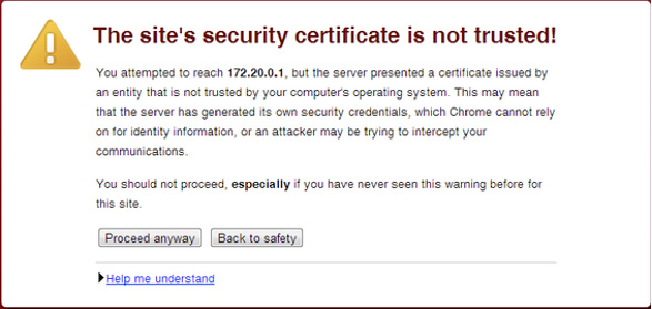
Figure 3-5 Certificate Warning Example
Later in this chapter, you will see how a CA can be used during the authentication process in a site-to-site VPN. Certificates are very popular, especially for larger deployments as well as those leveraging IKEv2.
Crypto Map Concepts
When building site-to-site VPNs, you need to configure crypto map policies. A crypto map in a VPN configuration serves two purposes. First, it needs to select data flows that need security processing. Second, it needs to define the policy for flows that are selected for security processing and the crypto peer toward which that traffic needs to flow. Crypto maps are applied to interfaces. The crypto map concept was first introduced with dedicated crypto concepts but later was expanded for IPsec. We will look more closely at configuring crypto maps when we cover building an IOS-based site-to-site VPN configuration, later in this chapter.
GETVPN/DMVPN/FlexVPN
When creating a site-to-site VPN, you need to consider your deployment approach. Cisco solutions can use a few site-to-site VPN frameworks, as discussed in the next few chapters. Let’s first look at GETVPN.
GETVPN
One approach we cover here is Group Encrypted Transport VPN (GETVPN), which eliminates the need for point-to-point tunnels and their associated overlay routing by instead using trusted groups. All group members in GETVPN share a common security association, also known as a group SA. The group SA enables group members to decrypt traffic that was encrypted by any other group member. In a GETVPN setup, there isn’t a need to negotiate point-to-point IPsec tunnels between members of a group; this means GETVPN is a tunnel-less option.
Benefits of GETVPN include the following:
• It provides native routing without requiring a tunnel overlay.
• Large-scale any-to-any IP connectivity is possible using a group IPsec security architecture.
• It is ideal for quality of service (QoS)—because it preserves the IP source and destination addresses—and multicast—because it integrates with multicast without replication issues.
• It is transport agnostic.
• It leverages an underlying IP VPN routing infrastructure without the need for an overlay routing control plane.
DMVPN
Another framework option is Dynamic Multipoint VPN (DMVPN). DMVPN is ideal when you need to support distributed applications such as voice and video. DMVPN can be deployed with capabilities such as QoS, IP Multicast, split tunneling, and routing-based failover. Larger networks use DMVPN for its ability to maintain performance for business-critical applications. Many organizations also use DMVPN to integrate services such as voice and video.
The following is a quick summery of the benefits of using DMVPN:
• The Multipoint GRE (mGRE) tunnel interface allows a single GRE interface to support multiple IPsec tunnels, reducing the size and complexity of the configuration.
• Dynamic discovery of IPsec tunnel endpoints and crypto profiles eliminates the need to configure static crypto maps defining every pair of IPsec peers, further simplifying the configuration.
• Routing protocols are used to exchange network information between the hub and spokes.
• It enables spokes to be deployed with dynamically assigned public IP addresses (behind an ISP’s router).
FlexVPN
A third option is FlexVPN, which is the Cisco version of the IKEv2 standard offering for both site-to-site and remote access VPNs. FlexVPN can be used with tunnel interfaces and can also support legacy VPN implementations using crypto maps. Think of FlexVPN as a way to combine multiple frameworks (crypto maps, EzVPN, and DMVPN) into a single comprehensible set and bind it all together into a more simplified and flexible approach to deploying VPNs. With FlexVPN, configurations typically begin with the crypto ikev2 command and also include smart defaults that help administrators use best practices when configuring a VPN.
The following list summarizes the benefits of FlexVPN:
• It can run along all existing IPsec VPNs.
• It can use GRE, allowing almost anything to run over it.
• IPsec secures the payload and supports both IPv4 and IPv6.
• Virtual interfaces allow per-spoke features such as firewalls, QoS, and ACLs.
• Multiple functionalities are embedded within one framework.
In the next few chapters, you will learn more about each of these approaches, when they would be ideal for a VPN deployment, and how to configure and troubleshoot each of them. Make sure you understand the fundamental components involved with each approach, such as what type of encryption and security associations are used.
Note
The SVPN 300-730 exam includes questions that validate your understanding of what technologies are used by each Cisco site-to-site VPN approach—that is, the components of a VPN. It might ask questions about relationships to IPsec, IKE, security associations, ESP, and AH. However, the exam will not test your knowledge of the details of Cisco hardware/models.
Now that we have covered the basic hardware, software, and protocols associated with site-to-site VPN architectures, we are ready to put these concepts into action. First, we will review how to configure a site-to-site VPN using Cisco routers. After that, we will look at how a site-to-site VPN can be configured on a Cisco security appliance like the ASA and Meraki Series.
Router Configuration with IKEv1
For the site-to-site VPN examples in this section, we focus on using Cisco routers (that is, IOS-based site-to-site VPN configurations). The first example uses Cisco ISR Series devices. The SVPN 300-730 exam is not likely to test you on the differences between the Cisco hardware models. You should, however, be able to configure a site-to-site VPN on any of these Cisco offerings because the core configuration steps are the same.
The first example shows how to set up a GRE with an IPsec tunnel. However, you could also set up this VPN by using only IPsec for the tunnel. In this first example, you will use IKEv1. Figure 3-6 shows a visual example of the desired configuration with the IP addresses used for this example.
Figure 3-6 Site-to-Site VPN Lab Diagram
The following lists the different parts required to plan and configure an IKEv1 site-to-site VPN for a Cisco router:
• Plan the VPN
• Configure the tunnel
• Configure Network Address Translation
• Configure encryption and IPsec
• Configure QoS
The following sections examine the details of these parts.
Planning the VPN
Earlier in this chapter, we listed some questions you should consider when planning how to deploy the best site-to-site VPN for your project. For this example, when you examine the answers to those questions, you find that the customer wants to leverage existing equipment because its current Cisco ASR 1000 Series routers are capable of supporting site-to-site VPN capabilities. Because the customer already owns the Cisco routers, it can be assumed that the people who will support this solution are familiar with Cisco and how IOS configuration works. This is a point in favor of continuing to use this equipment rather than acquiring an appliance option or another vendor router.
The next step is to make sure interfaces are available and determine what IP addresses will be used. For this setup, the headquarters gateway and remote office will connect over Ethernet interface 1/0 using the 172.24.2.0/24 network. Both locations have different inside networks, but there may be an overlap of internal IP addresses being used, which means NAT has to be used. NAT allows clients at each location to maintain their existing IP address but communicate over the VPN and access systems at each of the other location.
For this scenario, you will be accessing the headquarters router called Router_HQ1 and the remote office router called Router_Remote2. You will build the site-to-site VPN between these locations. You can start the configuration by setting up the tunnel between the headquarters and the remote office.
Configuring the Tunnel
Once you have planned how the VPN scenario will look and validated that the proper hardware and licensing exists, you are ready to set up the tunnel. You learned earlier in this chapter that tunneling encapsulates data packets inside a transport protocol using a virtual interface. However, you shouldn’t think of a tunnel as having a specific protocol. The tunnel is more of a passageway for a point-to-point encapsulation scheme. Because you are using a spoke-to-spoke configuration—that is, one spoke is the HQ and the other is the remote site—for this example, you are required to configure a separate tunnel for each link. Tunnel mode options include GRE, IPsec, and IPsec over GRE.
Why Use GRE with IPsec?
When it comes to deciding which tunneling option is right for your deployment, network redundancy (also known as network resilience) is an important factor to consider. GRE can be used with IPsec to pass routing updates between sites on an IPsec VPN. Without GRE, common routing protocols that rely on broadcast and multicast will not work over the IPsec tunnel. IPsec with GRE works by encapsulating a plaintext packet, and then IPsec (in either transport mode or tunnel mode) encrypts the packets. Essentially, GRE over IPsec allows the use of dynamic routing updates, and static IP security does not. Some protocols, such as BGP, can work without IPsec over GRE; however, IGRP, EIGRP, and RIP can’t pass updates without IPsec over GRE. OSPF’s default configuration also requires IPsec over GRE, but OSPF can be configured to function without GRE. Allowing for multicast routing updates used in protocols such as OSPF and EIGRP using IPsec over GRE permits the delineation of primary and secondary routers. If the primary is loss, route updates can be provided for failover to the secondary, thus achieving network resiliency. The same concept can apply using an IPsec over GRE site-to-site VPN connection between two VPN routers.
Let’s review how GRE and IPsec tunnel options work.
Configuring a GRE Tunnel
GRE tunnels are capable of handling transportation of multiprotocol and IP Multicast traffic between two locations that have only IP unicast connectivity. To configure a GRE tunnel for a site-to-site VPN using Cisco routers, you must configure the tunnel interface as well as a source and destination on both routers. This is done in global configuration mode. Follow these steps:
Step 1. Specify a tunnel interface number and configure the tunnel interface:
Router_HQ1(config)# interface tunnel 0
Router1(config-if)# ip address 192.168.3.3 255.255.255.0
Step 2. Specify the tunnel interface source address:
Router_HQ1(config-if)# tunnel source 192.168.2.4 255.255.255.0
Step 3. Specify the tunnel interface destination address:
Router_HQ1(config-if)# tunnel destination 192.168.2.5
Step 4. Optionally, configure GRE as the tunnel mode:
Router_HQ1(config-if)# tunnel mode gre ip
Note
You can also select IPsec as an option by using this command:
Router1(config-if)# tunnel mode ipsec ipv4
Step 5. Bring up the tunnel interface:
Router_HQ1(config)# interface tunnel 0
Router_HQ1(config-if)# no shutdown
%LINK-3-UPDOWN: Interface Tunnel0, changed state to up
Step 6. Configure traffic from the remote router by adding a route statement:
Router_HQ1(config-if)# exit
Router_HQ1(config)# ip route 10.1.4.0 255.255.255.0 tunnel 0
Step 7. Verify the tunnel, source, and destination and use a ping to test the connectivity, as shown in Example 3-1.
Example 3-1 Verifying the Tunnel, Source, and Destination and Pinging to Test Connectivity
Router_HQ1# show interfaces tunnel 1
Tunnel1 is up, line protocol is up
Hardware is Tunnel
MTU 1514 bytes, BW 9 Kbit, DLY 500000 usec,
reliability 255/255, txload 1/255, rxload 1/255
Encapsulation TUNNEL, loopback not set
Keepalive not set
Tunnel source 1101:1::1, destination 1501:1::1
Tunnel protocol/transport IPSEC/IPV6
Tunnel TTL 255
Tunnel transmit bandwidth 8000 (kbps)
Tunnel receive bandwidth 8000 (kbps)
Tunnel protection via IPSec (profile “tunpro”)
Last input 00:08:23, output 00:04:28, output hang never
Last clearing of “show interface” counters never
Input queue: 0/75/0/0 (size/max/drops/flushes); Total output drops: 3
Queueing strategy: fifo
Output queue: 0/0 (size/max)
5 minute input rate 0 bits/sec, 0 packets/sec
5 minute output rate 0 bits/sec, 0 packets/sec
39 packets input, 22734 bytes, 0 no buffer
Received 0 broadcasts, 0 runts, 0 giants, 0 throttles
0 input errors, 0 CRC, 0 frame, 0 overrun, 0 ignored, 0 abort
57 packets output, 30130 bytes, 0 underruns
0 output errors, 0 collisions, 0 interface resets
0 output buffer failures, 0 output buffers swapped out

Router_HQ1(config)# ping 192.168.3.6
Type escape sequence to abort.
Sending 5, 100-byte ICMP Echos to 192.168.3.6, timeout is 2 seconds:
!!!!!
Success rate is 100 percent (5/5), round-trip min/avg/max = 4/5/8 ms
You can configure IPsec with or without a GRE tunnel. Earlier in this chapter, you saw that IPsec has options for tunnel mode and transport mode. Basically, IPsec tunnel mode means the entire original IP datagram is encrypted and becomes the payload in a new IP packet; IPsec transport mode preserves the original source and addresses. The decision of which approach to use depends on concerns related to exposing the IP header to potential man-in-the-middle-attacks and whether support for special processing is required.
Configuring Network Address Translation
Our next focus is Network Address Translation (NAT), which we will break down into two parts. One part focuses on site-to-site networks avoiding address collision, and other focuses on inside to outside, and vice versa, address conversion. The first focus of NAT is designed for IP address conservation and limits the number of unique IP addresses assigned to systems on the network. Internal networks can use unregistered IP addresses (in ranges such as 192.168.0.0/16, 172.16.0.0/12, and 10.0.0.0/8) and connect them to the Internet. NAT essentially functions as a router connecting the private and public IP addresses by translating internal network addresses into legal addresses before the packets are forwarded on. NAT can be configured on a border router between the inside and outside, or public, domains; however, keep in mind that the goal is not to have NAT traffic within the tunnel. The goal is to use NAT with traffic between locations so there isn’t an overlap in IP addresses when one resource at the remote site connects to a resource within the HQ network. NAT is designed to protect against this.
Note
IKEv1 does not have built-in NAT traversal but IKEv2 does. However, Cisco routers support NAT traversal with IKEv1 even though it is not part of the specification.
The second NAT objective is to configure static translation with the goal of translating internal local IP addresses into globally unique IP addresses before sending packets to an outside network. This must be done if traffic is going to pass across a public network during site-to-site communication. Static translation uses a one-to-one mapping between the internal local address and an inside global address. This approach is useful when a host on the inside must be accessible by a fixed address from the outside.
Note
Dynamic NAT could also be used. It provides an address from a pool of addresses rather than checking for a one-to-one static mapping.
There are four addresses to consider with NAT:
• Inside local address: The IP address assigned to a host on the inside network. This is typically not a legitimate IP address and might be from an unregistered range.
• Inside global address: A legitimate IP address representing one or more inside local IP addresses to the outside public network.
• Outside local address: The IP address assigned to an outside host as it appears to the inside network. This may or may not be a legitimate address as it was allocated from address space that is routable on the inside network.
• Outside global address: The IP address assigned to a host on the outside network by the host owner. This means the address was allocated by the host owner rather than the inside network.
The NAT process can work by first having an inside host open a connection to an outside host. The border router checks the NAT table upon receiving the first packet from the inside host. If the router has a static translation, the router replaces the inside address with the IP address configured as its static translation address. If dynamic translation is being used, the inside address is translated into an address pulled from a dynamic address pool of publicly routable IP addresses, and an entry is added to the router’s NAT translation table. Future communication is translated by the border router, using the NAT translation table prepopulated by the static IP address assignment or dynamically populated as dynamic addresses are assigned to devices that do not have static translation assigned within the NAT translation table.
NAT Example
Next, let’s look at how to configure static NAT for our site-to-site VPN example. This is using the first NAT objective covered, because this chapter’s focus is for a site-to-site VPN connection. Remember that you need to bridge together two different networks that could be using the same inside IP address ranges. To address this concern, you can add NAT. Follow these steps:
Step 1. Create a static NAT translation:
Router_HQ1(config)# ip nat inside source static 10.1.6.5
10.2.2.2
Step 2. Specify the inside interface:
Router_HQ1config)# interface fastethernet 0/1
Step 3. Specify the interface as being an inside network:
Router_HQ1(config-if)# ip nat inside
Step 4. Specify the outside interface:
Router_HQ1(config-if)# interface serial 2/0
Step 5. Specify the interface facing the Internet:
Router_HQ1(config-if)# ip nat outside
Step 6. Verify the configuration, as shown in Example 3-2.
Example 3-2 Verifying the Configuration
Router_HQ1# show ip nat translations verbose
Pro Inside global      Inside local       Outside local      Outside
global
--- 10.2.2.2           10.1.6.5            ---                ---
    create 00:10:28, use 00:10:28, flags:
static

Router_HQ1# show running-config

interface FastEthernet0/1
 ip address 10.1.6.5 255.255.255.0
 no ip directed-broadcast
 ip nat inside

interface serial2/0
 ip address 172.16.2.2 255.255.255.0
 ip nat outside

ip nat inside source static 10.1.6.5 10.2.2.2
These steps assume that you are using the minimal required interfaces for NAT. You could configure multiple inside and outside interfaces, and this would be expected for multiple locations. You can also set up network redundancy.
Configuring Encryption and IPsec
As mentioned earlier in this chapter, IPsec is a framework that provides data confidentiality, data integrity, and data authentication between participating peers. As also mentioned earlier in this chapter, IPsec uses IKE to handle negotiation of protocols and algorithms as well as generate the encryption and authentication keys to be used by IPsec. As you saw earlier, certificate authorities can be used to validate trust between peers. Now it’s time to apply all of these ingredients to a router-based site-to-site configuration as part of establishing encryption and trust between peers. Make sure you understand how these ingredients apply for the SVPN 300-730 exam!
For this configuration example, you will use IKEv1 but will see what differences you would see if IKEv2 were used. First, you need to create IKE policies. IKE is enabled by default on Cisco routers—globally for all interfaces. IKE can also be enabled on individual interfaces for Cisco ASA appliances. You must create IKE policies for the different combinations of security algorithms. Remember that an IKE policy defines a combination of security parameters that is used during IKE negotiation. Once the two peers agree on which encryption and authentication algorithms are to be used, IKE authenticates the peers to each other. You can configure multiple IKE policies or use the default policy, which has the lowest priority and default parameter values.
IKE Policy Example
Note
An IKE policy configured with a higher priority (that is, a low number) triggers before the default policy unless you adjust the default policy’s priority.
Follow these steps to create a custom IKE policy—but remember that you could just use the default IKE policy instead on modern Cisco routers:
Step 1. Enter config-isakmp mode and create a policy name:
Router_HQ1(config)# crypto isakmp policy 1
Step 2. Specify the encryption algorithm (ideally AES):
Router_HQ1(config-isakmp)# encryption aes
Step 3. Specify the hash algorithm (MD5 or SHA):
Router_HQ1(config-isakmp)# hash sha
Step 4. Name the authentication method:
Router_HQ1(config-isakmp)# authentication pre-share
Here you use pre-shared keys, but you could use RSA encrypted nonces (rsa-encr) or RSA signatures (rsa-sig) instead.
Note
The authentication method used impacts additional steps after your policy is created. Remember that this example uses IKEv1.
Step 5. Name the Diffie-Hellman group identifier, where group 5 is 1536 bits and group 2 is 1024 bits:
Router_HQ1(config-isakmp)# group 5
Step 6. Specify the security association’s lifetime, in seconds:
Router_HQ1(config-isakmp)# lifetime 86400
86400 represents 1 day.
Step 7. Exit back to the global configuration mode:
Router_HQ1(config-isakmp)# exit
Step 8. Optionally, specify the time interval for IKE keepalive packets (where the default is 10 seconds) as well as the retry interval (in this case, 3 seconds):
Router_HQ1(config)# crypto isakmp keepalive 15 3
Authentication Options
Remember that the authentication you selected for your IKE policy determines which additional steps must be taken to complete the configuration. Each authentication option requires different additional configuration steps. The following is a quick summary of the authentication options you could use:
• RSA signature method (rsa-sig): If you use RSA signatures as the authentication method in your IKE policy, you must configure all peers to obtain certificates from a CA.
• RSA encrypted nonces method (rsa-encr): If the RSA encrypted nonces method is used in your IKE policy, you need to make sure each peer has the other peer’s public keys because certificates are not being used.
• Pre-shared keys (pre-share): If pre-shared keys are used, you need pre-shared keys.
Pre-shared Key Example
For this example, you will use pre-shared keys because that is what is used in the previous IKE configuration. The steps to create pre-shared keys are as follows:
Step 1. Specify the ISAKMP identity, which can be the address or hostname the router will use when communicating with remote routers during the IKE negotiations:
Router_HQ1(config)# crypto isakmp identity address
Step 2. Specify the shared key the router will use with remote routers. For this example, the key is test123, and remote address is 192.168.2.5:
Router_HQ1(config)# crypto isakmp key test123 address 192.168.2.5
Step 3. At the remote router (router2), specify the ISAKMP identity, which can be the address or hostname the router will use when communicating with remote routers during the IKE negotiations:
Router_Remote2(config)# crypto isakmp identity address
Step 4. At the remote router (router2), specify the shared key the router will use with remote routers. For this example, the key is test123, and remote router is 192.168.2.4:
Router_Remote2(config)# crypto isakmp key test123 address 192.168.2.4
Note
This must be the same key that the other router used.
Digital Certificate Example
You might also have decided to use digital certificates as the authentication method, which is very popular for mid-sized to larger deployments. Next, you will see how that would be configured on a Cisco IOS router. In this case, you can assume that you will use the IOS default ISAKMP policy, which uses DES, SHA, and RSA signatures. You can also assume the default Diffie-Hellman group 1 and a day lifetime (that is, 86,400 seconds), based on how you configured the previous steps in the sample site-to-site VPN configuration on a Cisco IOS router.
Follow these steps to configure the headend of the VPN:
Note
Each router peer must be enrolled with a CA.
Step 1. Log in to the router headend, access config mode, and declare a CA by using the domain name of the CA (in this case, VPN_CA):
Router_HQ1(config)# crypto pki trustpoint VPN_CA
Step 2. Specify the URL of the SCEP server in place of url:
Router_HQ1(ca-trustpoint)# enrollment url url
Step 3. Optionally, specify RA (registration authority) mode if your CA system includes an RA:
Router_HQ1(ca-trustpoint)# enrollment mode ra
Cisco routers automatically determine the mode, but you can manually specify it.
Step 4. Specify the location of the LDAP server if your CA provides an RA and supports LDAP, replacing url with the URL:
Router_HQ1(ca-trustpoint)# query url url
Step 5. Optionally, specify that other peer certificates can still be accepted by your router, even if the appropriate certificate revocation list (CRL) is not accessible to your router:
Router_HQ1(ca-trustpoint)# revocation-check crl none
Step 6. Optionally, specify how many times the router will continue to send unsuccessful certificate requests before ending attempts (where number is the number of attempts):
Router_HQ1(ca-trustpoint)# enrollment retry count number
Step 7. Exit ca-identity configuration mode:
Router_HQ1(ca-identity)# exit
Step 8. Verify your policy:
Router_HQ1(config-isakmp)#show crypto isakmp policy
Protection suite priority 1
encryption algorithm: DES - Data Encryption Standard (56 bit keys)
hash algorithm: Secure Hash Standard
authentication method: Pre-Shared Key
Diffie-Hellman group: #1 (768 bit)
lifetime: 86400 seconds, no volume limit
Configuring a Crypto Map
One final encryption step to cover is configuring crypto maps. You learned earlier in this chapter that a crypto map defines the policy for flows that are selected to be processed as well as the crypto peer toward which traffic will be sent.
Crypto maps can be static or dynamic. If you use static crypto maps, you define the specific peers and the policies each one is going to use. This is fine for smaller networks, but it can be a challenge as you scale to a larger site-to-site VPN design. Dynamic crypto maps use a shared policy, which means multiple peers can use the same policy characteristics. An example could be multiple remote offices using DHCP as part of their policy. Think of using dynamic crypto maps as a way to simplify configuration from the headend because you don’t have to statically map each peer’s individual policy.
Note
Another option that could be used is a virtual tunnel interface (VTI). There are some key differences between crypto maps and VTIs:
• Crypto maps require an ACL, and VTIs do not.
• Running routing protocols over the VPN can be more challenging with crypto maps than with VTIs because VTIs can participate in the routing process.
• Crypto maps can be more difficult to configure.
We cover dynamic virtual tunnel interfaces and virtual tunnel interfaces in Chapter 4, “Group Encrypted Transport VPN (GETVPN).”
Crypto Map Example
In the following configuration example, you will create a crypto map entry that uses IKE to establish the security association. You need to go back to the headquarters router and follow these steps:
Step 1. Create the crypto map and specify a location address. For this case, you can use local-address serial 2/0 and call it cryptomap01:
Router_HQ1(config)# crypto map cryptomap01
local-address serial 2/0
This step is required only if you have previously used the loopback command or if you are using GRE tunnels.
Step 2. Enter the crypto map configuration mode and specify a sequence number for the crypto map you created in step 1 (which is cryptomap01):
Router_HQ1(config)# crypto map cryptomap01 2 ipsec-isakmp
In this case, you configure the crypto map to use IKE to establish the security associations. You should be in the crypto map config mode.
Step 3. Create an extended access list to specify which traffic will be protected by IPsec and which traffic will not be protected by IPsec:
Router_HQ1(config-crypto-map)# match address 111
Step 4. Specify the remote IPsec peer (in this case, the remote router) by hostname or IP address:
Router_HQ1(config-crypto-map)# set peer 172.23.2.7
Step 5. Create a transform set, which is a combination of individual IPsec transforms designed to enact a specific security policy for traffic, and call it Transform1:
Router_HQ1(config)# crypto ipsec transform-set Transform1 esp-aes esp-sha-hmac
Step 6. Indicate which transform sets are allowed for this crypto map entry, and then type exit:
Router_HQ1(config-crypto-map)# set transform-set Transform1
Router_HQ1(config-crypto-map)# exit
You can list multiple transform sets in order of priority, with the highest priority set first. In this case, you use Transform1 as your only set.
Step 7. Verify the crypto map, as shown in Example 3-3.
Example 3-3 Verifying the Crypto Map
Router_HQ1# show interfaces tunnel 1
Crypto Map: “s4second” idb: Serial2/0 local address: 172.16.2.2
Crypto Map “s4second” 2 ipsec-isakmp
        Peer = 172.23.2.7
        Extended IP access list 111
            access-list 111 permit ip
                source: addr = 10.2.2.2/255.255.255.0
                dest:   addr = 10.1.5.3/255.255.255.0S
        Current peer: 172.23.2.7
        Security-association lifetime: 4608000 kilobytes/3600 seconds
        PFS (Y/N): N
        Transform sets={proposal4,}
Applying Crypto Maps
Now that the crypto map is created, you need to apply it to an interface. You need to do this for each interface IPsec traffic will flow through. Think of this as the crypto map interface telling the router to have any traffic that will travel through that interface to be applied against the crypto map. The crypto map will tell the router which policy to use during the connection or security association negotiation.
Follow these steps to apply the crypto map to the serial 2/0 interface of the headquarters router:
Step 1. Specify the physical interface to apply the crypto map against (in this case, serial 2/0) and enter configuration mode:
Router_HQ1(config)# interface serial 2/0
Step 2. Apply the crypto map you created:
Router_HQ1(config-if)# crypto map cryptomap01
Step 3. Exit back to global configuration mode:
Router_HQ1(config-if)# exit
Step 4. Go to privileged EXEC mode and clear the existing IPsec security associations so any changes are used immediately:
Router_HQ1# clear crypto sa
Step 5. As shown in Example 3-4, verify that the crypto map is applied to the interface by using the command show crypto map interface against the specific interface you applied the crypto map against.
Example 3-4 Verifying That the Crypto Map Is Applied to the Interface
Router_HQ1# show crypto map interface serial 2/0
Crypto Map “s4second” 2 ipsec-isakmp
        Peer = 172.23.2.7
        Extended IP access list 111
            access-list 111 permit ip host 10.2.2.2 host 10.1.5.3
        Current peer:172.23.2.7
        Security association lifetime:4608000 kilobytes/1000 seconds
        PFS (Y/N):N
        Transform sets={ proposal4, }
Configuring QoS
At this point, your site-to-site VPN is configured, but you want to make sure the performance over the VPN is acceptable to users; that is, you could configure QoS against higher-priory traffic to improve the VPN service. Think of QoS as a method of creating better and more predictable service. You can use QoS to improve loss characteristics, avoid or deal with network congestion, shape traffic, and enforce traffic priorities. QoS is out of scope for this chapter and the SVPN exam, but know it is an additional option once the VPN is up.
Note
QoS can provide value, but it can also cause problems if not used properly. For example, if you prioritize traffic for one application, you may be degrading service for another. Make sure to plan traffic priorities before deploying a QoS strategy.
Router Configuration with IKEv2
Earlier in this chapter, you learned about the differences between IKEv1 and IKEv2. Essentially, IKE is an encryption protocol that handles request and response actions. IKE ensures that traffic is secure by establishing and handling the SA attribute within an authentication suite, which is usually IPsec.
Primary Router Configuration Example
You need to know both IKEv1 and IKEv2 for the SVPN 300-730 exam, and you will see both options deployed over real networks. Therefore, this section walks through a VPN configuration using IKEv2 with IPsec.
Note
IKE concepts are foundational for future chapters that leverage both IKEv1 and IKEv2.
Defining the IKEv2 Keyring
To begin router configuration with IKEv2, you need to configure the IKEv2 keyring, which consists of pre-shared keys associated with an IKEv2 profile. These pre-shared keys perform authentication. An IKEv2 keyring is a repository of symmetric and asymmetric pre-shared keys and is independent of the IKEv1 keyring.
The IKEv2 keyring is associated with an IKEv2 profile, which you will configure in a later step. The IKEv2 keyring gets its virtual routing and forwarding (VRF) context from the associated IKEv2 profile. Follow these steps to configure the IKEv2 keyring:
Step 1. Define the new keyring:
Router_HQ1(config)# crypto ikev2 keyring KR1
Step 2. Specify the peer name:
Router_HQ1(config-ikev2-keyring)# peer PeerRemote
Step 3. Specify the IP address of the peer router:
Router_HQ1(config-ikev2-keyring)# address 192.168.2.5
Step 4. Specify the pre-shared key that will be used between peers:
Router_HQ1(config-ikev2-keyring)# pre-shared-key Secret_Key
Defining the IKEv2 Proposal
Next, you need to define the IKEv2 proposal, which consists of transforms. Much as with IKEv1, with IKEv2 transforms are used in the negotiation of IKE SAs. Follow these steps to define the IKEv2 proposal:
Step 1. Define the name for the proposal for the remote router:
Router_HQ1(config)# crypto ikev2 proposal PRO-Remote
Step 2. Specify the encryption type, integrity type, and group:
Router_HQ1(config-ikev2-proposal)# encryption aes-cbc-256
Router_HQ1(config-ikev2-proposal)# integrity sha512
Router_HQ1(config-ikev2-proposal)# group 24
Defining IKEv2 Policies
Next, you need to build an IKEv2 policy, which contains IKEv2 proposals. Proposals are used to negotiate the encryption algorithm, integrity algorithm, PRF algorithms, and Diffie-Hellman group. Follow these steps:
Step 1. Define the name for the policy:
Router_Remote2(config)# crypto ikev2 policy POL-Remote
Step 2. In the policy configuration state, name the proposal created in step 1:
Router_Remote2(config-ikev2-policy)# proposal PRO-Remote
Defining a Crypto ACL for IPsec Secured Traffic
A crypto ACL is not like a normal ACL; it isn’t used to permit or deny traffic as normal ACLs do. Instead, a crypto ACL permit state is used to identify the traffic that is to be secured using IPsec. You use a crypto ACL deny statement to identify the traffic that you do not want to secure. Essentially, you use a crypto ACL to define which traffic will and will not be encrypted. Follow these steps:
Step 1. Define the extended ACL, which you can call HQ-Remote-CACL:
Router_HQ1(config)# ip access-list extended HQ-Remote-CACL
Step 2. Define the traffic that will be permitted meaning (that is, the traffic that will be encrypted, which in this case is 192.168.2.0 class C traffic):
Router_HQ1 config-ext-nacl# permit ip 192.168.2.0 0.255.255.255
Defining a Transform Set
As with IKEv1, you use a transform set to define how the data traffic will flow between IPsec peers. You define the transform set in one step:
Step 1. Define the transform set with parameters:
Router_HQ1(config)# crypto ipsec transform-set TS_Remote esp-aes esp-sha512-hmac
Defining an IKEv2 Profile
Creating an IKEv2 profiles is similar to the process of building an IKEv1 ISAKMP profile. You define the keyring, remote IP address, and local and remote authentication:
Step 1. Define the name of the IKEv2 profile:
Router_HQ1(config)# crypto ikev2 profile Remote-Profile
Step 2. Specify the IP address of router2:
Router_HQ1(config-ikev2-profile)# match identity remote address 192.168.2.5 255.255.255.2555
Step 3. Define the local authentication, remote authentication, and keyring:
Router_HQ1(config-ikev2-profile)# authentication local pre-share
Router_HQ1(config-ikev2-profile)# authentication remote pre-share
Router_HQ1(config-ikev2-profile)# keyring local KR1
Defining Crypto Maps
You need to create crypto maps to connect together all pieces of the IPsec configuration. You do this by using a crypto map, which can contain one or more entries. In this case, you need to include the crypto ACL, transform set, remote peer, and other information, such as the security lifetime for the data connection in this VPN:
Step 1. Specify the name for the crypto map (in this case, CMAP-Remote2):
Router_HQ1(config)# crypto map CMAP-Remote2 10 ipsec-isakp
Step 2. In the crypto map configuration state, set the IP address for the remote peer:
Router_HQ1(config-crypto-map)# set peer 192.168.2.4
Step 3. Define the other items you built in previous steps, including the group, transform set, and profile, and specify the lifetime of the data connection:
Router_HQ1(config-crypto-map)# set pfs group24
Router_HQ1(config-crypto-map)# set security-association lifetime seconds 3600
Router_HQ1(config-crypto-map)# set transform-set TS_Remote
Router_HQ1(config-crypto-map)# set ikev2-profile Remote-Profile
Router_HQ1(config-crypto-map)# match address HQ-Remote-CACL
Activating Crypto Maps
Finally, you apply the crypto maps to interfaces that will send traffic through the VPN. For this example, assume that the HQ1 router will use interface gi0/0:
Router_HQ1(config)# interface gi0/0
Router_HQ1(config-if)# crypto map CMAP-Remote2
Repeating Similar Steps for the Other Router
You need to repeat on the Remote2 router steps similar to those you just took. Slight changes are needed to point toward the HQ1 router. Here is a summary of the configuration steps:
Step 1. Define the keyring on Router2:
Router_Remote2(config)# crypto ikev2 keyring KR1
Step 2. Name the other peer (in this case, PeerHQ1):
Router_Remote2(config-ikev2-keyring)# peer PeerHQ1
Step 3. Specify the IP address of the peer router (in this case, the HQ router):
Router_Remote2(config-ikev2-keyring)# address 192.168.2.4
Step 4. Specify the pre-shared key you created on HQ1:
Router_Remote2(config-ikev2-keyring)# pre-shared-key Secret_Key
Step 5. Define the name for the proposal for the remote router:
Router_Remote2(config)# crypto ikev2 proposal PRO-HQ1
Step 6. In the proposal configuration state, specify the encryption type, integrity type, and group:
Router_Remote2(config-ikev2-proposal)# encryption aes-cbc-256
Router_Remote2(config-ikev2-proposal)# integrity sha512
Router_Remote2(config-ikev2-proposal)# group 24
Step 7. Define the name for the policy:
Router_Remote2(config)# crypto ikev2 policy POL-HQ1
Step 8. In the policy configuration state, name the proposal created in step 7:
Router_Remote2(config-ikev2-policy)# proposal PRO-HQ1
Step 9. Define the extended ACL:
Router_Remote2(config)# ip access-list extended Remote-HQ-CACL
Step 10. Define the traffic that will be permitted (that is, the traffic that will be encrypted):
Router_Remote2(config-ext-nacl)# permit ip 192.168.3.0 0.255.255.255
Step 11. Name the transform set and provide parameters:
Router_Remote2(config)# crypto ipsec transform-set TS_HQ1 esp-aes esp-sha512-hmac
Step 12. Define the name of the IKEv2 profile:
Router_Remote2(config)# crypto ikev2 profile HQ1-Profile
Step 13. Set the IP address of the HQ1 router:
Router_Remote2(config-ikev2-profile)# match identity remote address 192.168.2.4 255.255.255.2555
Step 14. Define the local authentication, remote authentication, and keyring:
Router_Remote2(config-ikev2-profile)# authentication local pre-share
Router_Remote2(config-ikev2-profile)# authentication remote pre-share
Router_Remote2(config-ikev2-profile)# keyring local KR2
Step 15. Name the crypto map (in this case, CMAP-HQ1):
Router_HQ1(config)# crypto map CMAP-HQ1 10 ipsec-isakp
Step 16. Set the IP address for the remote HQ1 peer:
Router_HQ1(config-crypto-map)# set peer 192.168.2.5
Step 17. Define the parameters you created in the previous steps:
Router_HQ1(config-crypto-map)# set pfs group24.
Router_HQ1(config-crypto-map)# set security-association lifetime seconds 3600
Router_HQ1(config-crypto-map)# set transform-set TS_HQ1
Router_HQ1(config-crypto-map)# set ikev2-profile PRO-HQ1
Router_HQ1(config-crypto-map)# match address Remote-HQ-CAL
Step 18. Apply the crypto map to an interface:
Router_HQ1(config)# interface gi0/0
Router_HQ1(config-if)# crypto map CMAP-HQ1
Note
The detailed router configuration examples provided in this chapter should give you an understanding how an IOS-based site-to-site VPN can be built. We will look more at IOS-based VPN configuration of routers in upcoming chapters. The following section shows how to perform a similar configuration using a few different Cisco security appliance options.
Appliance Configuration
Configuring a site-to-site VPN for a Cisco security appliance is a different process from configuring a site-to-site VPN for a router, although the architecture and design concepts are similar. You can access and modify the configuration of a Cisco appliance such as an ASA firewall by using a few approaches. You could access the command-line interface (CLI) and perform the steps required to set up a site-to-site VPN. Another option is to use a graphical user interface (GUI) option such as Cisco Adaptive Security Device Manager (ASDM), Cisco Security Manager (CSM), or Cisco Defense Orchestrator (CDO).
For the first Cisco appliance example, you will build a site-to-site VPN on a Cisco ASA. You will use IKEv1 IPsec for a site-to-site tunnel between a Cisco 5515-X Series ASA running software Version 9.2.x and a Cisco 5515-X Series ASA running Version 8.2.x. As a reminder, UDP point 500 needs to be available for ISAKMP, IP protocol 50 for ESP, and protocol 51 for AH. UDP 4500 also needs to be opened for the IPsec data plane when NAT traversal is needed. Figure 3-7 shows this lab setup. You will use both ASDM and CLI for the following configuration examples.
Note
ASA Version 8.4 and later provide support for both IKEv1 and IKEv2.
Figure 3-7 ASA Site-to-Site Configuration
ASDM Example
This section shows you how to build a site-to-site VPN by using a GUI like ASDM to configure a Cisco ASA. You can access Cisco ASDM by going to the management IP address of the ASA in a web browser and following the prompts to install ASDM. In this example, as shown in Figure 3-8, the management interface is 198.19.40.253.
Note
You must set up access for ASDM, or you won’t be able to access the GUI. This should be part of your initial setup of the ASA solution, along with other steps, including setting a username and password.
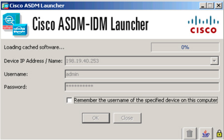
Figure 3-8 Cisco ASDM Launcher
When you are able to access ASDM, you can simplify the site-to-site deployment by using the Site-to-Site VPN wizard, as shown in these steps:
Step 1. Find the Site-to-Site VPN wizard by going to Wizards > VPN Wizards > Site-to-Site VPN Wizard (see Figure 3-9).
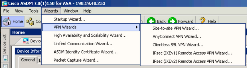
Figure 3-9 Accessing the Site-to-Site VPN Wizard in ASDM
Step 2. On the wizard home page, which includes a visual diagram and a video of how site-to-site VPNs can be configured, click the Next button (see Figure 3-10).
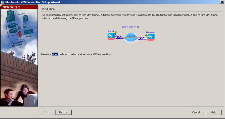
Figure 3-10 ASDM Site-to-Site VPN Wizard Introduction Page
Step 3. When you are asked to configure the peer IP address for the site-to-site VPN, use 192.168.1.1 on the remote ASA, which you will call ASA SITE-B, and specify that the VPN access interface is the outside interface (see Figure 3-11). Click the Next button.
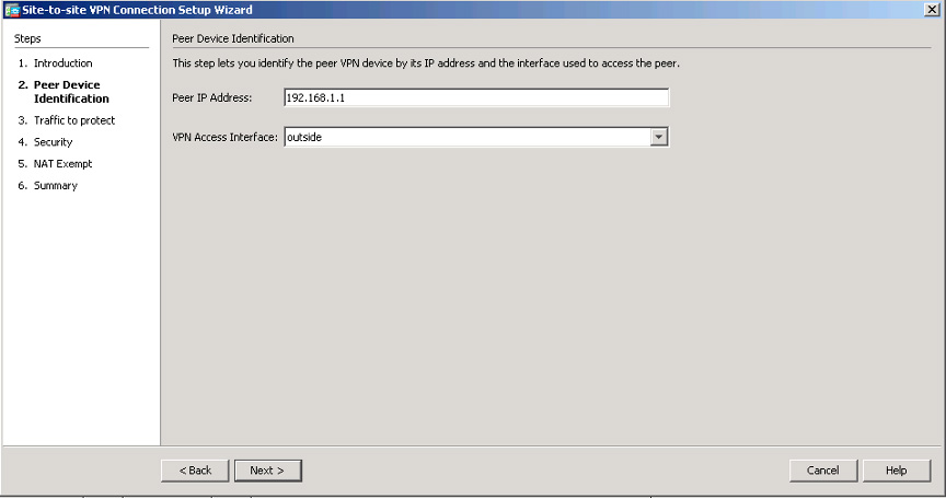
Figure 3-11 ASDM Site-to-Site VPN Wizard Peer Device Setup Page
Step 4. Define the local and remote networks, which represent the traffic source and destination: 10.2.2.0/24 for the local network and 10.1.1.0/24 for the remote network (see Figure 3-12). Click Next.
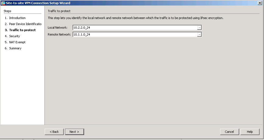
Figure 3-12 ASDM Site-to-Site VPN Wizard Connection Setup Page
Step 5. On the Security page, configure a pre-shared key (see Figure 3-13). This process is similar to the process you used to configure the site-to-site VPN on the Cisco routers. This key must be the same on both ASAs. Click Next.
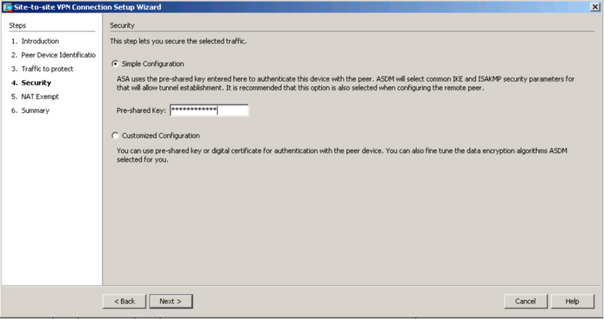
Figure 3-13 ASDM Site-to-Site VPN Wizard Peer Device Setup Page
Step 6. On the next screen, where you build the NAT rule for this VPN setup, choose whether any network such as the ASA side host/network should be exempt from the NAT rule (see Figure 3-14). This is important to ensure that NAT is performed properly. Click Next.
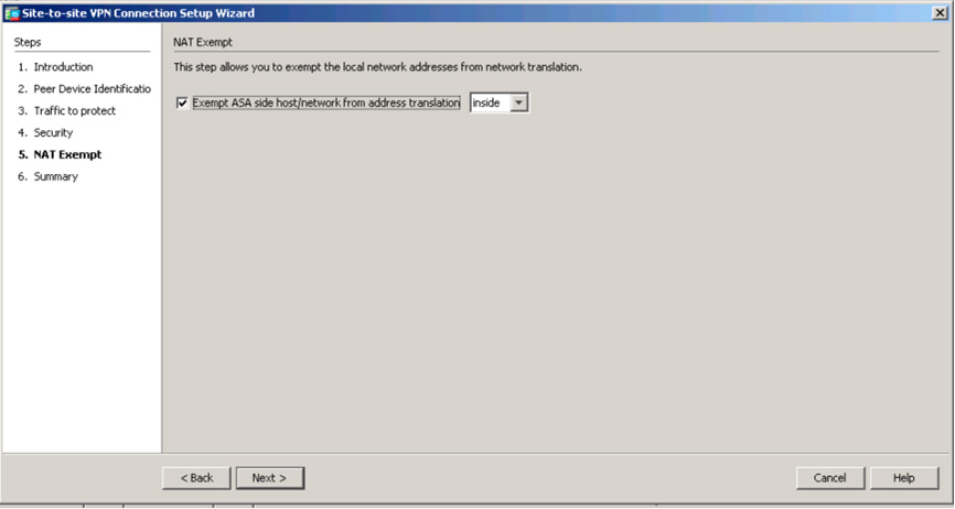
Figure 3-14 ASDM Site-to-Site VPN Wizard NAT Example Page
Step 7. On the final page of the wizard, read the summary of the configuration that will be pushed to the ASA (see Figure 3-15). This is a good place to review the associated command-line code with your configuration to ensure that you understand what command-line entries are being created by the ASA Site-to-Site VPN wizard. Click Finish to complete the wizard.
Note
For the SVPN 300-730 exam, we highly recommend that you make sure you understand the associated command-line entries that are created by the Site-to-Site VPN wizard. The wizard shows you all of the command-line code it is about to deploy, and you should study that output!
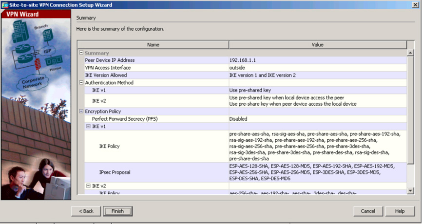
Figure 3-15 ASDM Site-to-Site VPN Wizard Summary Page
Step 8. Verify that the site-to-site VPN is built by going to Monitoring > VPN. You should be able to see the peer IP address, the protocol used to build the tunnel, the encryption algorithm, the time when the tunnel came up, the up-time of the tunnel, and the number of packets that have been passed through the tunnel. You will learn more about monitoring and troubleshooting VPNs on the ASA in Chapter 10.
Note
Click the Refresh button to update the information shown on the VPN page.
ASA Command-Line Example
In the example in this section, you will build on the same site-to-site VPN you have begun to create, but this time you will do so by using the ASA CLI. You have already built the ASA configuration on the HQ site, and now you need to build the ASA configuration at the remote site. In this example, you will build the connection back to the headquarters. This means you will build an IKEv1 IPsec site-to-site VPN on an ASA running Version 8.4 or later software. The final result will be similar to the CLI output displayed on the configuration summary page of the ASDM Site-to-Site VPN wizard.
You begin the CLI configuration by configuring IKEv1, and then you configure IPsec. Follow these steps:
Step 1. Enable IKEv1 on the outside interface:
Crypto ikev1 enable outside
Step 2. Create an IKEv1 policy that defines the methods to be used for hashing, authentication, Diffie-Hellman group, lifetime, and encryption:
crypto ikev1 policy 1
!The 1 in the above command refers to the Policy suite priority(1 highest, 65535 lowest)
authentication pre-share
encryption aes
hash sha
group 2
lifetime 86400
Step 3. Under the IPsec attributes, create a tunnel group and configure the peer IP address as well as the tunnel pre-shared key:
tunnel-group 192.168.1.1 type ipsec-l2l
tunnel-group 192.168.1.1 ipsec-attributes
ikev1 pre-shared-key cisco
! Note the IKEv1 keyword at the beginning of the pre-shared-key command.
Step 4. Create an access list that defines the traffic to be encrypted and sent through the tunnel. There can be one or more entries, depending on how many subnets will be involved with the site-to-site VPN. For this example, the traffic that will be using the VPN will be coming from the source 10.2.2.0 subnet and going to the 10.1.1.0 network. Since you are using Version 8.4 or later, you need to build network objects for these subnets and permit this traffic by using an access list:
object network 10.2.2.0_24
subnet 10.2.2.0 255.255.255.0
object network 10.1.1.0_24
subnet 10.1.1.0 255.255.255.0
access-list 100 extended permit ip object 10.2.2.0_24 object 10.1.1.0_24
Note
In ASA Version 8.4 and later, object groups serve as containers for networks, subnets, host IP addresses, or multiple objects. For the SVPN 300-730 exam, make sure you understand how object groups work. You can find a general overview of ASA objects in the latest ASA documentation.
Step 5. Configure the transform set, which must use the keyword IKEv1 and which must also be created on the other ASA:
crypto ipsec ikev1 transform-set myset esp-aes esp-sha-hmac
Step 6. Configure a crypto map and apply it to the outside interface. The crypto map should include the peer IP addresses, the access list that contains the VPN traffic, the transform set, and an optional Perfect Forward Secrecy setting used to create a new pair of Diffie-Hellman keys that are used to protect associated data:
crypto map outside_map 20 match address 100
crypto map outside_map 20 set peer 192.168.1.1
crypto map outside_map 20 set ikev1 transform-set myset
crypto map outside_map 20 set pfs
crypto map outside_map interface outside
Step 7. Create a NAT rule and ensure that the VPN traffic is not subjected to any other NAT rule (see Example 3-5).
Example 3-5 Creating a NAT Rule for Sourcing Traffic
nat (inside,outside) 1 source static 10.2.2.0_24 10.2.2.0_24 destination static
 10.1.1.0_24 10.1.1.0_24 no-proxy-arp route-lookup

object-group  network to a dynamic range of IP addresses within the
10.1.1.0/24 subnet. Remember that dynamic NAT means a IP address comes
from a pool of addresses. 10.x.x.x_SOURCE
 network-object  10.4.4.0 255.255.255.0
 network-object  10.2.2.0 255.255.255.0

object network 10.x.x.x_DESTINATION
 network-object  10.3.3.0 255.255.255.0
 network-object  10.1.1.0 255.255.255.0

nat (inside,outside) 1 source static 10.x.x.x_SOURCE 10.x.x.x_SOURCE destination
 static 10.x.x.x_DESTINATION  10.x.x.x_DESTINATION no-proxy-arp route-lookup
Note
When you plan to use multiple subnets, you must create object groups with all source and destination subnets. Those object groups must be used in the NAT rule.
Step 8. Create an internal group policy to define specific settings that will apply to the tunnel, including VPN attributes, such as LT2P using IPsec, SSL VPN client, Web VPN, and the VPN idle timeout:
group-policy SITE_A internal
vpn-tunnel-protocol ikev1
vpn-idle-timeout none
The vpn-idle-timeout attribute allows the tunnel to stay idle without any traffic. You can define the idle time by using minutes or state none, as you did in the example to keep the tunnel up regardless of whether traffic is seen.
Step 9. Set the default group policy under the tunnel group:
tunnel-group 192.168.1.1 general-attributes
default-group-policy SITE_A
This means the default settings that you did not define in the group policy will be pulled from a global default policy.
Step 10. To verify that the site-to-site VPN is working, verify that the Phase 1 configuration is active on each side by checking the status of the security association of the ASA 5515:
show crypto ikev1 sa

Active SA: 1
   Rekey SA: 0 (A tunnel will report 1 Active and 1 Rekey SA during rekey)
Total IKE SA: 1

1   IKE Peer: 192.168.1.1
    Type    : L2L           Role    : initiator
    Rekey   : no            State   : MM_ACTIVE
Step 11. Verify Phase 1 on the ASA 5510:
show crypto isakmp sa

Active SA: 1
   Rekey SA: 0 (A tunnel will report 1 Active and 1 Rekey SA during rekey)
Total IKE SA: 1

1   IKE Peer: 172.16.1.1
    Type    : L2L           Role    : initiator
    Rekey   : no           State   : MM_ACTIVE
Step 12. Verify phase 2 on the ASA 5515 by using the same command (see Example 3-6).
Example 3-6 Verifying Phase 2 on an ASA 5515 by Using show crypto ipsec sa
show crypto ipsec sa

interface: FastEthernet0
   Crypto map tag: outside_map, local addr. 192.168.1.1
  local ident (addr/mask/prot/port): (10.1.1.0/255.255.255.0/0/0)
  remote ident (addr/mask/prot/port): (10.2.2.0/255.255.255.0/0/0)
  current_peer: 172.16.1.1
    PERMIT, flags={origin_is_acl,}
   #pkts encaps: 20, #pkts encrypt: 20, #pkts digest 20
   #pkts decaps: 20, #pkts decrypt: 20, #pkts verify 20
   #pkts compressed: 0, #pkts decompressed: 0
   #pkts not compressed: 0, #pkts compr. failed: 0,
   #pkts decompress failed: 0, #send errors 0, #recv errors 0
    local crypto endpt.: 192.168.1.1, remote crypto endpt.: 172.16.1.1
    path mtu 1500, media mtu 1500
    current outbound spi: 3D3
    inbound esp sas:
     spi: 0x136A010F(325714191)
       transform: esp-aes esp-sha-hmac ,
       in use settings ={Tunnel, }
       slot: 0, conn id: 3442, flow_id: 1443, crypto map: outside_map
       sa timing: remaining key lifetime (k/sec): (4608000/52)
       IV size: 8 bytes
       replay detection support: Y
    inbound ah sas:
    inbound pcp sas:

    inbound pcp sas:
    outbound esp sas:
     spi: 0x3D3(979)
       transform: esp-aes esp-sha-hmac ,
       in use settings ={Tunnel, }
       slot: 0, conn id: 3443, flow_id: 1444, crypto map: outside_map
       sa timing: remaining key lifetime (k/sec): (4608000/52)
       IV size: 8 bytes
       replay detection support: Y
    outbound ah sas:
    outbound pcp sas

  #pkts encaps: 20, #pkts encrypt: 20, #pkts digest 20
  #pkts decaps: 20, #pkts decrypt: 20, #pkts verify 20
  #pkts compressed: 0, #pkts decompressed: 0
  #pkts not compressed: 0, #pkts compr. failed: 0,
  #pkts decompress failed: 0, #send errors 0, #recv errors 0
   local crypto endpt.: 172.16.1.1, remote crypto endpt.: 172.16.1.1
   path mtu 1500, media mtu 1500
   current outbound spi: 3D3
   inbound esp sas:
    spi: 0x136A010F(325714191)
      transform: esp-aes esp-sha-hmac ,
      in use settings ={Tunnel, }
      slot: 0, conn id: 3442, flow_id: 1443, crypto map: outside_map
      sa timing: remaining key lifetime (k/sec): (4608000/52)      IV size: 8 bytes
      replay detection support: Y
   inbound ah sas:
   inbound pcp sas:
   inbound pcp sas:
   outbound esp sas:
    spi: 0x3D3(979)
      transform: esp-aes esp-sha-hmac ,
      in use settings ={Tunnel, }
      slot: 0, conn id: 3443, flow_id: 1444, crypto map: outside_map
      sa timing: remaining key lifetime (k/sec): (4608000/52)
      IV size: 8 bytes
      replay detection support: Y
   outbound ah sas:
   outbound pcp sas

   Rekey SA: 0 (A tunnel will report 1 Active and 1 Rekey SA during rekey)
Total IKE SA: 1

1   IKE Peer: 172.16.1.1
    Type    : L2L             Role    : initiator
    Rekey   : no              State   : MM_ACTIVE
Note
You can debug the site-to-site configuration by using the following command for Phase 1:
debug crypto ikev1 255
Use the following command for Phase 2:
debug crypto ipsec 255
We cover troubleshooting in more detail in Chapter 6.
Cisco Secure Firewall Example
This section walks through another Cisco appliance configuration—this one for a basic site-to-site VPN on Cisco Secure Firewall. This section assumes that you have two or more Cisco Secure Firewall systems configured and are building a site-to-site VPN.
Note
The SVPN 300-730 exam currently does not include Cisco Secure Firewall configuration as part of the learning objectives. However, we cover it because Cisco Secure Firewall is a widely deployed option and a popular upgrade option from a Cisco ASA investment.
To build a site-to-site VPN using Cisco Secure Firewall, follow these steps:
Step 1. Log in to your Cisco Secure Firewall solution (see Figure 3-16).
Figure 3-16 Cisco Secure Firewall Login Screen
Step 2. To access the site-to-site VPN capabilities, go to Devices > VPN > Site to Site (see Figure 3-17). If you haven’t yet built a site-to-site VPN on the Cisco Secure Firewall solution, the next screen shows that you have nothing configured.
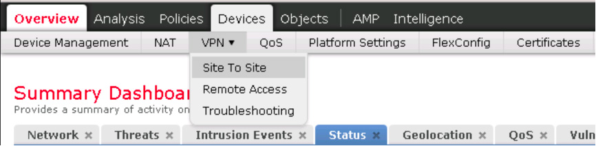
Figure 3-17 Accessing Site to Site in Cisco Secure Firewall
Step 3. Click the Add VPN button on the right side of the screen to add a new VPN and select Firepower Threat Defense Device (see Figure 3-18).
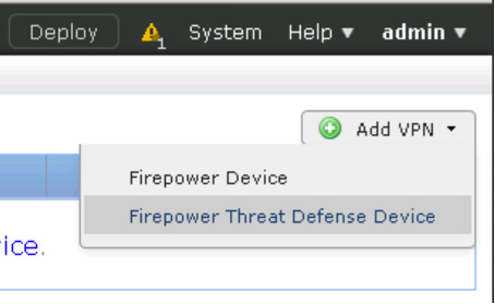
Figure 3-18 Selecting Firepower Threat Defense for a VPN Configuration Example
Step 4. In the main site-to-site VPN page, give your new VPN a name. It is recommended to include FTD in the name because that is the device type you are configuring. Next to Network Topology, choose Point to Point (see Figure 3-19).
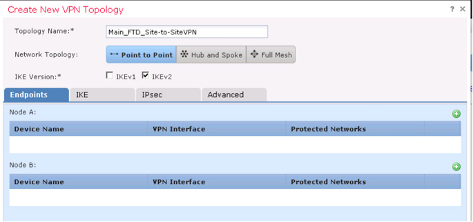
Figure 3-19 Configuring a New Site-to-Site VPN with Cisco Secure Firewall
Step 5. Click the green plus sign icon to add devices or nodes and choose which device to add, which interface will be part of the VPN, what IP address to use, the connection type, and associated certificate networks that will be protected by the VPN (see Figure 3-20). Click OK. Repeat this step for each Cisco Secure Firewall solution included in the site-to-site VPN setup.
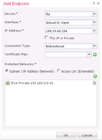
Figure 3-20 Choosing Nodes to Participate in the VPN
Step 6. On the next tab, select configuration options for IKEv2, as shown in Figure 3-21.
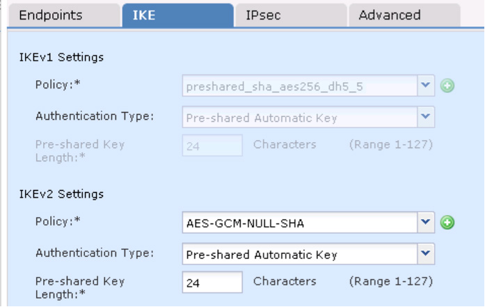
Figure 3-21 IKEv1 and IKEv2 Configuration Options for Cisco Secure Firewall
Step 7. If you are using IPsec, select the IPsec tab and choose whether you are using tunnel or transport mode as well as the other settings shown in Figure 3-22.
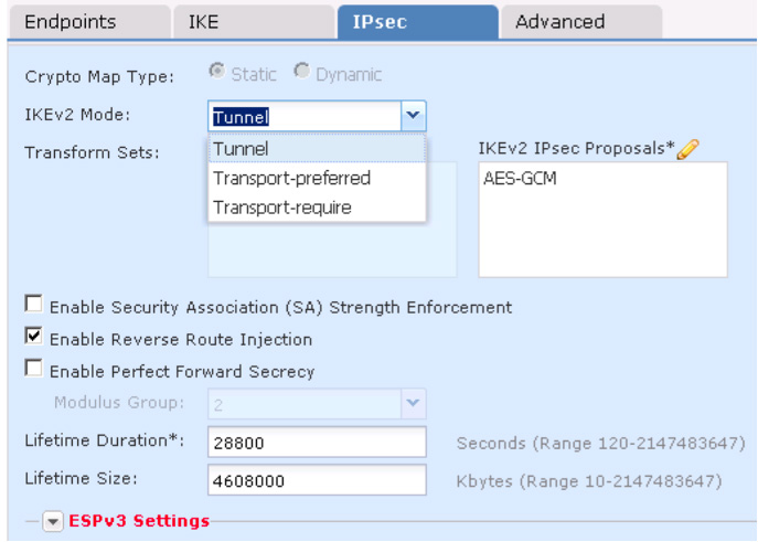
Figure 3-22 IPsec Configuration Options for Cisco Secure Firewall
Step 8. On the Advanced tab, select advanced settings for IKE, IPsec, and the VPN tunnel, as shown in Figure 3-23. You can see that there are various options for setting up keepalives when traffic is not seen across the VPN, peer validation, IKEv2 security associations, IPsec fragmentation prior to encryption, and various certificate map settings. (You saw similar configuration options with the Cisco ASA site-to-site VPN setup earlier in this chapter.)
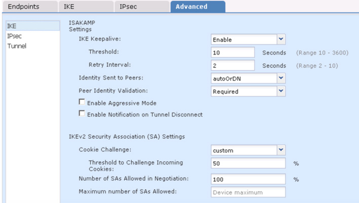
Figure 3-23 Advanced VPN Configuration Options for Cisco Secure Firewall
When your options are selected, click Save and deploy the changes to all the associated Cisco Secure Firewall appliances. You can monitor the VPN by using system messages, VPN health events, system logs, or the CLI.
Note
You should notice a lot of similarity between using Cisco routers, Cisco Secure Firewall, and Cisco ASA technologies to set up site-to-site VPNs. Make sure you understand the fundamental concepts of creating site-to-site VPNs within each platform as you prepare for the SVPN 300-730 exam. You need to understand each step as well as the order of the steps and why each step is being used. You also need to be able to compare each step to alternative options. For example, the exam might ask you how IKEv2 could be used as an alternative to IKEv1 or whether either version of IKE is supported. We will go much deeper into all of these concepts over the next few chapters, as we cover the different Cisco site-to-site deployment options.
Cisco Meraki Example
One last example that is a bit different from the site-to-site VPN configurations we have covered thus far in the chapter is setting up a site-to-site VPN on a Cisco Meraki solution.
Note
The SVPN 300-730 exam currently does not include Cisco Meraki configuration as part of the learning objectives; however, we cover it because Cisco Meraki is a widely deployed option and secure access service edge (SASE), becoming an industry standard.
In Chapter 2, we touched on the Meraki one-touch site-to-site VPN. Now it’s time to see it in action. This section assumes that you have purchased and deployed two or more Meraki MX appliances and have the proper license to run a site-to-site VPN.
To access any configuration options for Cisco Meraki, you need to access the cloud-based management dashboard at https://dashboard.meraki.com. This is how you access your personal cloud Meraki manager for all Meraki products. When you access the Meraki main dashboard, you see the different product options as well as options to view aspects of your entire organization, as seen by Cisco Meraki. This is your centralized window into your entire Meraki deployment.
Follow these steps to set up a Meraki site-to-site VPN:
Step 1. Find the site-to-site VPN options by going to Security & SD-WAN > Configure > Site-to-site VPN (see Figure 3-24).
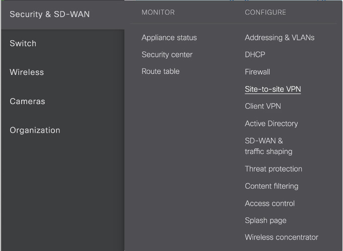
Figure 3-24 Accessing the Cisco Meraki Site-to-Site VPN Configuration
Step 2. On the next screen, where you see the site-to-site VPN options, select the Site-to-Site VPN option and either Hub (representing a full mesh) or Spoke (representing a hub and spoke) to add the current Meraki MX to the VPN configuration. By default, Off is selected to remove the currently selected MX from any site-to-site configuration (see Figure 3-25). When you select Hub or Spoke, new configuration options appear below the high-level VPN options page.
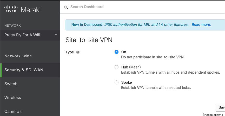
Figure 3-25 Cisco Meraki Site-to-Site VPN Enablement Page
If this is the first MX you are setting up for the site-to-site VPN, you see a warning similar to the one shown in Figure 3-26, stating that no other hubs are in the VPN. Below that message will be the VPN setting options.
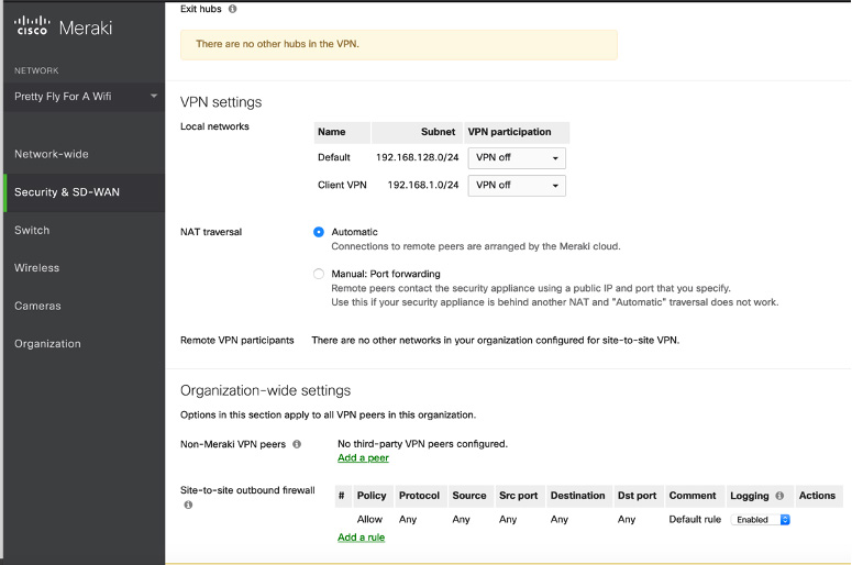
Figure 3-26 Cisco Meraki Site-to-Site VPN Configuration Page
Step 3. Scroll past the warning message to the configuration settings. You have the option to choose whether the local networks and client VPN networks are to be part of the site-to-site VPN configuration. By default, they are both not included. You can set NAT to Automatic or use the Manual Port Forwarding option. If you have a remote VPN set up, you are permitted to include those participants within your site-to-site VPN, and check boxes are available to add them to your site-to-site VPN configuration.
Step 4. In the Organization-wide Settings section, select other MX systems as well as the firewall rules you want to open for site-to-site VPN outbound traffic. Click Save.
Step 5. Repeat steps 1–4 to build a site-to-site VPN between two or more MX appliances.
As you can see, setting up a site-to-site VPN with Meraki devices is relatively easy. All the options you need are on a single page in the Cisco Meraki management GUI.
High Availability
One final site-to-site VPN concept we need to cover is high availability. Your VPNs will likely support mission-critical traffic, and redundancy and resilience are likely important to your site-to-site VPN design.
An organization is likely to have high-availability requirements to ensure that its network doesn’t go down when there is a failure on one or more site-to-site VPN nodes. You can take several approaches to adding high availability to your site-to-site VPN architecture. One approach is purchasing redundant equipment and configure a method for the secondary system to take over when the primary system is no longer available. Another approach is to acquire backup equipment but not have it set up. A third method is to change how traffic is routed when a primary system goes down. By using one or more of these approaches, you can avoid a broken VPN situation. Best practice is to consider implementing a combination of these approaches to increase your network’s resilience against interrupted site-to-site VPN service.
High Availability Options
Let’s look at each of the possible approaches to implementing high availability with a site-to-site VPN architecture:
• Active/active: This high-availability design involves splitting traffic between two nodes so that both VPN-providing technologies are being actively used. If one system goes down, the other system takes on the load for both systems, acting as the solo primary VPN technology (up to its capacity). This approach provides a few benefits, including offering high availability while also leveraging both VPN solutions for maximum return on investment. The disadvantages of this approach are sizing both appliances to be able to handle the load for all traffic, maintaining traffic that is split between two appliances, and the likely increased costs as both VPN-providing technologies are expected to be used, requiring the full cost for both appliances. Cost for this option depends on the vendor, technology, and licenses used.
• Active/standby: With this approach, one VPN appliance acts as the active primary VPN-providing technology, and there is a second technology that is not used unless the primary system becomes unavailable. For automated failover, there is a heartbeat setup between the primary and standby systems, where the standby system periodically validates that the primary system is active. If the heartbeat is interrupted between the primary and secondary systems, a failover occurs, causing the secondary system to become the primary VPN provider. Failover can occur automatically or manually, depending on the technology and licenses being used. It is common for this approach to cost less than an active/active design because one system is not expected to be used unless a failover occurs. The actual costs of the failover solution depends on the technology and licenses used.
• Cold standby: With this approach, a second VPN solution is ready to be used in a failover configuration but is not set up. If the primary system goes down, manual effort is required to transfer the VPN to the failover system.
• Routed standby: This approach creates redundancy by using a networking approach rather than dedicating hardware. All systems that access the primary VPN know how to access it, based on its available IP address and routing that permits traffic to that VPN source. A routed failover changes the routing and/or IP address of the primary system and routes traffic somewhere else until the primary system goes down. It’s possible that a routed standby is essentially how a failover occurs between two active/active or active/standby VPN appliances or traffic could just be permitted to certain sources while the primary system is down. The details of this approach depend on the vendor used and how the network is configured.
Consider the following factors as you plan for high availability in a site-to-site VPN:
• Available hardware/software
• Cost of the complete support
• Required licenses
• Location of redundant systems
• Required training and support
• Available bandwidth to support redundant links
• Compliance and backup requirements
• Desired level of redundancy and resilience to VPN outages
High Availability Considerations
The best approach for your organization depends on a few factors. If you plan to use an active/active or active/standby design, you need to ensure that the equipment is sized properly. An active/active approach is likely to have larger hardware and higher costs than an active/standby approach. If you plan to automate the failover between the VPN solutions, you need to make sure the proper level of bandwidth is available to support the heartbeat between the VPN technologies. Keep in mind that any lag that disrupts the connection between the VPN systems causes unwanted failover to occur.
When considering which Cisco security appliances to use, you need to think about the different requirements that must be met in order for different high-availability capabilities to be supported. Here is a summary of considerations for Cisco security appliances configured for high availability:
• Must use the same model.
• Must have same number and types of interfaces. (For the Cisco Secure Firewall 9300 chassis, all interfaces must be preconfigured in FXOS identically before high availability is enabled.)
• Must have the same modules installed, if any are used.
• Must have the same RAM installed.
There are also software and configuration requirements to consider regarding Cisco security appliances providing high availability. Here is a summary of those requirements:
• Must be in the same context mode (single or multiple).
• If configured for single mode, must be in the same firewall mode (routed or transparent).
• Must have the same major (first number) and minor (second number) software version on both appliances. The only exception is that different versions can be used during the upgrade process while maintaining failover.
• Both appliances must use the same AnyConnect images.
• For the Cisco Secure Firewall 9300 Series, appliances must have the same flow offload mode (enabled or disabled).
Note
For the SVPN 300-730 exam, you need to know the expectations for what is required on Cisco ASA appliances for high availability to work. This includes expected communication between the systems as well as the hardware and configuration items that must match between both systems.
When using Cisco technology to perform high availability, specific traffic is passed between the systems. If one system needs to monitor whether the other system is alive, hello messages (also known as keepalives) need to be continuously passed. The current state of the units—either active or standby—is also beaconed back and forth to ensure that both systems know their current role. MAC address and link status messages are passed back and forth to ensure that the systems are communicating with the proper peers. Finally, configuration replication and synchronization occur to ensure that the backup system has the latest configuration if it is required to become the primary unit.
High Availability Costs
You will find there are different costs for different high-availability options as you meet with different vendors. Some vendors charge less for active/standby than active-active since the backup system is used only when a failover occurs. As mentioned in Chapter 2, Cisco offers flexible licensing that does not count usage against a license unless the capability is being used. An example for site-to-site VPN design would be to acquire a 90-day license for the standby appliance and a full license for the primary system. The assumption would be that the standby system would never be used unless the primary system went down, and 90 days would be enough time to troubleshoot and reestablish connectivity to the primary. Also, keep in mind that both ASAs need to have the same license type for this to work.
If you are looking to save costs, a cold standby option might be the best choice. You can find different variations of a cold standby based on the readiness of the backup system. For the most basic cold standby, you can purchase redundant hardware and store it at another location. This approach would require labor to unbox and stand up the system in the event that the primary VPN-providing technology goes down. Industry experts recommend having a cold standby system unboxed, racked, and ready to be used, with a base configuration installed. It is also recommended to set up a system that periodically pulls the latest configuration from the primary solution and stores it in a location from which you can download in the event that the primary system goes down. This would allow the cold standby system to upload a recent configuration as it takes over the primary system role.
High Availability Technology Considerations
Another consideration is requirements for the technology being used. We already pointed out the importance of bandwidth between systems using an automated failover approach. Some systems may also require dedicated interfaces for the heartbeat. For example, the Cisco ASA uses an unused data interface for the failover link. This means a normal networking interface can’t also act as the heartbeat, which could be a showstopper if your design includes currently running equipment that may not have the available processing power, bandwidth, or interfaces to support the site-to-site failover design.
Another example of limitations for failover is options within a Cisco router. On a Cisco router, only the stateless form of IPsec failover is supported. The stateless failover in routers uses protocols such as Hot Standby Router Protocol (HSRP) to provide primary-to-secondary cutover and also allows the active and standby VPN gateways to share a common virtual IP address. You need to make sure the routers involved with the site-to-site VPN are capable of supporting your architecture requirements.
Bidirectional Forwarding Detection
One important IOS failover concept is Bidirectional Forwarding Detection (BFD). Cisco routers can use a BFD protocol to provide fast-forwarding path failure detection for all media types, encapsulations, topologies, and routing protocols. Such a protocol allows administrators to detect forwarding path failures much more quickly than is possible with traditional protocol hello mechanisms.
IOS Failover Example
Because you will likely want to set up failover on an IOS-based site-to-site VPN, let’s examine how these failover settings look on a Cisco router. To configure BFD on a Cisco router, follow these steps:
Step 1. Create a BFD single-hop template:
Router(config)# bfd-template single-hop bfdtemplate1
Step 2. Configure the transmit and receive intervals between BFD packets and the number of BFD control packets that must not be seen before BFD finds that the peer is no longer available:
Router(bfd-config)# interval min-tx 120 min-rx 100 multiplier 3
Step 3. Enter the interface intended for failover and provide either an IPv4 or IPv6 address:
Device(config)# interface FastEthernet 4/0
Device(config)# interface gigabitethernet 0/0/0
Device(config-if)# ip address 10.201.201.1 255.255.255.0
Device(config-if)# ipv6 address 2001:db8:1:1::1/32
Step 4. Enable the BFD template:
Router(config)# bfd template bfdtemplate1. bfd template template name
One final failover concept you need to consider is how a configuration can be exported from a Cisco IOS or security appliance–based site-to-site VPN. Enabling such an export provides an additional redundancy plan that is activated when both primary and backup systems go down. In addition, the backed-up configuration can be used for a cold standby option, and it can also be used to validate whether unwanted changes or corruption has occurred in your active VPN architecture. You can export configuration manually on almost all Cisco technologies, and many security appliances and routers offer the ability to specify automatic exportation of configuration on a regular basis.
Summary
This chapter explores the steps involved in developing and configuring site-to-site VPNs. It starts by looking at planning for a future site-to-site VPN project. It also covers many key concepts and components used when building site-to-site VPNs. In addition, this chapter walks through the configuration required to build a site-to-site VPN between Cisco IOS routers. It also looks at building site-to-site VPNs between Cisco security appliances, including Cisco ASA appliances, Cisco Secure Firewall, and Cisco Meraki. Finally, this chapter covers high-availability concepts as they apply to site-to-site VPN architectures.
Now that you have a basic understanding of how site-to-site VPN technology works, it’s time to look more closely at the different VPN frameworks Cisco offers to support site-to-site capabilities. First up is a closer look at GETVPN.
References
Aditya, Venkata, and Rahul Govindan (April 13, 2018). Configure IKEv1 IPsec Site-to-Site Tunnels with the ASDM or CLI on the ASA. Retrieved from https://www.cisco.com/c/en/us/support/docs/security/asa-5500-x-series-next-generation-firewalls/119141-configure-asa-00.html
Anand, Adity (July 14, 2018). SSL Strip & How Awesome It Is! Retrieved from https://medium.com/bugbountywriteup/ssl-strip-how-awesome-it-is-a0eb79e28bcc
Cisco Secure Firewall Appliances Next-Generation Firewall Datasheet. Retrieved from https://www.cisco.com/c/en/us/products/collateral/security/firepower-ngfw/datasheet-c78-742480.html
Cisco IOS VPN Configuration Guides. Retrieved from https://www.cisco.com/c/en/us/td/docs/security/vpn_modules/6342/vpn_cg.html
Crypto Maps. Retrieved from https://www.cisco.com/c/en/us/td/docs/wireless/asr_5000/21/IPSec/21_IPSec-Reference/b_21_IPSec_chapter_0110.pdf
Firepower Management Center Configuration Guide, Version 6.2. Retrieved from https://www.cisco.com/c/en/us/td/docs/security/firepower/620/configuration/guide/fpmc-config-guide-v62/firepower_threat_defense_site_to_site_vpns.html
Latosiewicz, Marcin (August 29, 2017). Crypto Map Based IPsec VPN Fundamentals—Negotiation and Configuration. Retrieved from https://community.cisco.com/t5/security-documents/crypto-map-based-ipsec-vpn-fundamentals-negotiation-and/ta-p/3153502
Mocan, Tim (February 20, 2019). What Is IKEv2? Retrieved from https://www.cactusvpn.com/beginners-guide-to-vpn/what-is-ikev2/
Site-to-Site VPN Settings. Retrieved from https://documentation.meraki.com/MX/Site-to-site_VPN/Site-to-site_VPN_Settings
Snyder, Joel (March 21, 2011). Cisco Has Long History with VPNs. Retrieved from https://www.networkworld.com/article/2200809/cisco-has-long-history-with-vpns.html
What Are Certificate Authorities & Trust Hierarchies? Retrieved from https://www.globalsign.com/en/ssl-information-center/what-are-certification-authorities-trust-hierarchies/
Exam Preparation Tasks
As mentioned in the section “How to Use This Book” in the Introduction, you have a couple of choices for exam preparation: the exercises here, Chapter 11, “Final Preparation,” and the exam simulation questions in the Pearson Test Prep software online.
Review All Key Topics
Review the most important topics in the chapter, noted with the key topics icon in the outer margin of the page. Table 3-3 lists these key topics and the page number on which each is found.
Table 3-3 Key Topics for Chapter 3
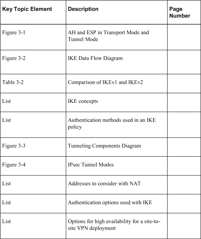
Complete Tables and Lists from Memory
Print a copy of Appendix C, “Memory Tables” (found on the companion website), or at least the section for this chapter, and complete the tables and lists from memory. Appendix D, “Memory Tables Answer Key” (also on the companion website), includes completed tables and lists to check your work.
Define Key Terms
Define the following key terms from this chapter and check your answers in the glossary: