CHAPTER 4
AIR OPERATIONS
I. PREPLANNED AIR RESUPPLY OPERATIONS:
- Automatic Resupply Plan. This plan provides for initial automatic replacement of essential equipment and supplies, primarily communications equipment, immediately after infiltration.
- Preinfiltration planning includes: DZ selection, DZ markings, drop time and date, and supplies to be dropped.
- Immediately after infiltration provide for replacement of essential equipment and supplies, particularly communications equipment.
- The automatic resupply plan may be received as planned, modified, or may be cancelled after infiltration, once contact is established with the SFOB.
- If the detachment fails to contact the SFOB after infiltration, the drop is executed as preplanned.
- Emergency Resupply Plan. This plan provides for emergency replacement of supplies and equipment essential to individual survival, communications, and combat throughout the time that the detachment is in the operational area.
- Preinfiltration planning includes: provisional DZ selection to be confirmed after infiltration, DZ markings, drop date and time based upon the emergency, and supplies to be dropped.
- After infiltration is completed and communications established with the SFOB, the emergency DZ location (which is known only to the special forces detachment members) is either confirmed or a new location is designated.
- The preplanned emergency resupply drop is normally executed after the detachment misses a specified, consecutive number of scheduled communications contacts.
II. DROP ZONES:
- General. The selection of a DZ must satisfy the requirements of both the aircrew and the reception committee. The aircrew must be able to locate and identify the DZ. The reception committee selects a site that is accessible, reasonably secure, and permits safe delivery of incoming personnel and/or supplies.
- Air considerations.
- Desirable terrain features.
- The general area surrounding the site must be relatively free from obstacles which may interfere with safe flight.
- Flat or rolling terrain is desirable; however, in mountainous or hilly country, sites selected at higher elevations such as level plateaus can be used.
- Small valleys or pockets completely surrounded by hills are difficult to locate and should not normally be used.
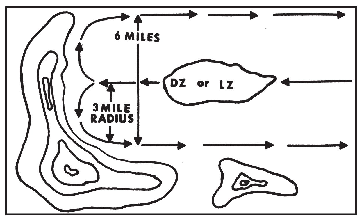
- In order to afford the air support unit flexibility in selecting the IP, it is desirable that the aircraft be able to approach the target site from any direction.
- There should be an open approach quadrant of at least 90° to allow the aircrew a choice when determining their approach track from the IP.
- DZs having a single clear line of approach are acceptable for medium aircraft, provided there is a level turning radius of 3 miles, (5 kilometers) on each side of the site (1 mile or 1.5 kilometers for light aircraft) (Figure 1).
- Rising ground or hills of more than 1,000 feet (305 meters) elevation above the surface of the site should normally be at least 10 miles from DZ for night operations. In exceptionally mountainous areas deviations from this requirement may be made. Any deviation will be noted in the DZ report.
- Deviations from the aforementioned minimum distances cause the aircraft to fly at higher than desirable altitudes when executing the drop.
- Weather in drop areas. The prevailing weather conditions in the area must be considered. Ground fogs, mists, haze, smoke, and lowhanging cloud conditions may interfere with visual signals and DZ markings. Excessive winds also hinder operations.
- Obstacles. Due to the low altitudes at which operational drops are conducted, consideration must be given to navigational obstacles in excess of 300 feet (90 meters) above the level of the DZ and within a radius of 5 miles (8 kilometers). If such obstacles exist and are not shown on the issued maps, they must be reported.
- Enemy air defenses. Drop sites should be located so as to preclude the aircraft flying over or near enemy air installations when making the final approach to the DZ.
- Desirable terrain features.
- Ground Considerations.
- Shape and size.
- The most desirable shape for a DZ is square or round. This permits a wider choice of aircraft approach directions than is normally the case with rectangular-shaped sites.
- The required length of a DZ depends primarily on the number of units to be dropped and the length of their dispersion pattern.
- Dispersion occurs when two or more personnel or containers are released consecutively from an aircraft in flight. The long axis of the landing pattern is usually parallel to the direction of flight (Figure 2).
- Dispersion is computed using the rule-of-thumb formula: 1/2 speed of aircraft (knots) × exit time (seconds) = dispersion (meters). Exit time is the elapsed time between the exits of the first and last items.
- The length of the dispersion pattern represents the absolute minimum length required for DZs. If personnel are to be dropped, a safety factor of at least 100 meters is added to each end of the DZ site.
- The width of rectangular-shaped DZs should allow for minor errors in computation of wind drift.
- The use of DZs measuring less than 300 ×300 meters should be avoided.
- Surface.
- The surface of the DZ should be reasonably level and free from obstructions such as rocks, trees, fences, etc. Tundra and pastures are types of terrain which are ideal for both personnel and cargo reception.
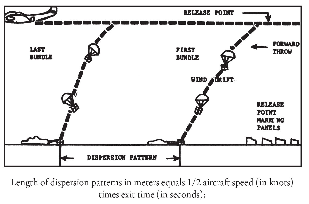
Figure 2. Computation of Dispersion.
- Personnel DZs located at comparatively high elevations (6,000 feet (1,640 meters) or higher) should, where possible, utilize soft snow or grasslands, due to the increased rate of parachute descent.
- Swamps and low marshy ground, normally less desirable in the summer, and paddy fields when dry often make good drop zones.
- Personnel and cargo can be received on water DZs.
- Minimum depths for reception of personnel is 4 feet and arrangements must be made for rapid pickup.
- The surface of the water must be clear of floating debris or moored craft, and there should be no protruding boulders, ledges, or pilings.
- The water must also be clear of underwater obstructions to a depth of 4 feet.
- Water reception points should not be near shallows or where currents are swift.
- Minimum safe water temperature is 50°F. (10°C.)
- Supply drop zones may, in general, utilize any of the following types of surfaces:
- Surfaces containing gravel or small stones no larger than a man’s fist.
- Agricultural ground, although in the interest of security, it is inadvisable to use cultivated fields.
- Sites containing brush or even tall trees; however, marking of the DZ and the recovery of containers is more difficult.
- Marsh, swamp, or water sites, provided the depth of water or growth of vegetation will not result in loss of containers.
- The surface of the DZ should be reasonably level and free from obstructions such as rocks, trees, fences, etc. Tundra and pastures are types of terrain which are ideal for both personnel and cargo reception.
- Ground Security. The basic considerations for ground security are that the DZ be:
- Located to permit maximum freedom from enemy interference.
- Isolated or in a sparsely populated area.
- Accessible to the reception committee by concealed approach and withdrawal routes.
- Adjacent to areas suitable for the caching of supplies and disposition of aerial delivery equipment.
- Shape and size.
III. REPORTING DROP ZONES:
- Drop Zone Data. The minimum drop zone data which is reported includes:
- Code name. Extracted from the SOI, also, indicate if primary or alternate DZ.
- Location. Complete military grid coordinates of the center of the DZ.
- Open Quadrant. Measured from center of DZ, reported as a series of magnetic azimuths. The open quadrant indicates acceptable aircraft approaches (Figure 3).
- Track. Magnetic azimuth of required or recommended aircraft approaches (Figure 3).
- Obstacles. Those that are over 300 feet (90 meters) in elevation above the level of the DZ, within a radius of 6 miles (8 kilometers) and which are not shown on the issued maps. Obstacles are reported by description, magnetic azimuth, and distance from the center of the DZ (Figure 4).
- Reference point. A landmark shown on the issued maps, reported by name, magnetic azimuth and distance from the center of the DZ (Figure 4). Used with (2) above in plotting the DZ location.
- Date/time drop requested.
- Items requested. Extracted from the catalog supply system.
- Additional Items. In special situations, additional items may be required, e.g., additional reference points, navigational check points in the vicinity of the DZ, special recognition and authentication means. Sub-paragraphs (7) and (8) above are included only when requesting a resupply mission in conjunction with the reporting of the DZ.
- Azimuths. Azimuths are reported as magnetic and in three digits. With the exception of the aircraft track, all azimuths are measured from the center of the DZ. Appropriate abbreviations are used.
- Initial Points (IPs). It is desirable to reconcile the requested aircraft track with an identifiable landmark that may be used by the aircrew as an initial point (IP). The IP, located at a distance of 5 to 15 miles (8-24 kilometers) from the DZ, is the final navigational checkpoint prior to reaching the target. Upon reaching the IP, the pilot turns to a predetermined magnetic heading that takes him over the DZ within a certain number of minutes (Figure 5). The following features constitute suitable IPs:
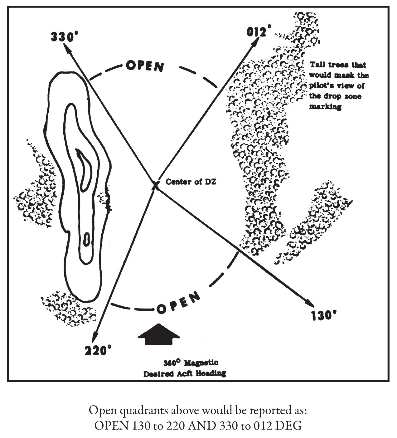
Figure 3. Computation of Open Quadrant.
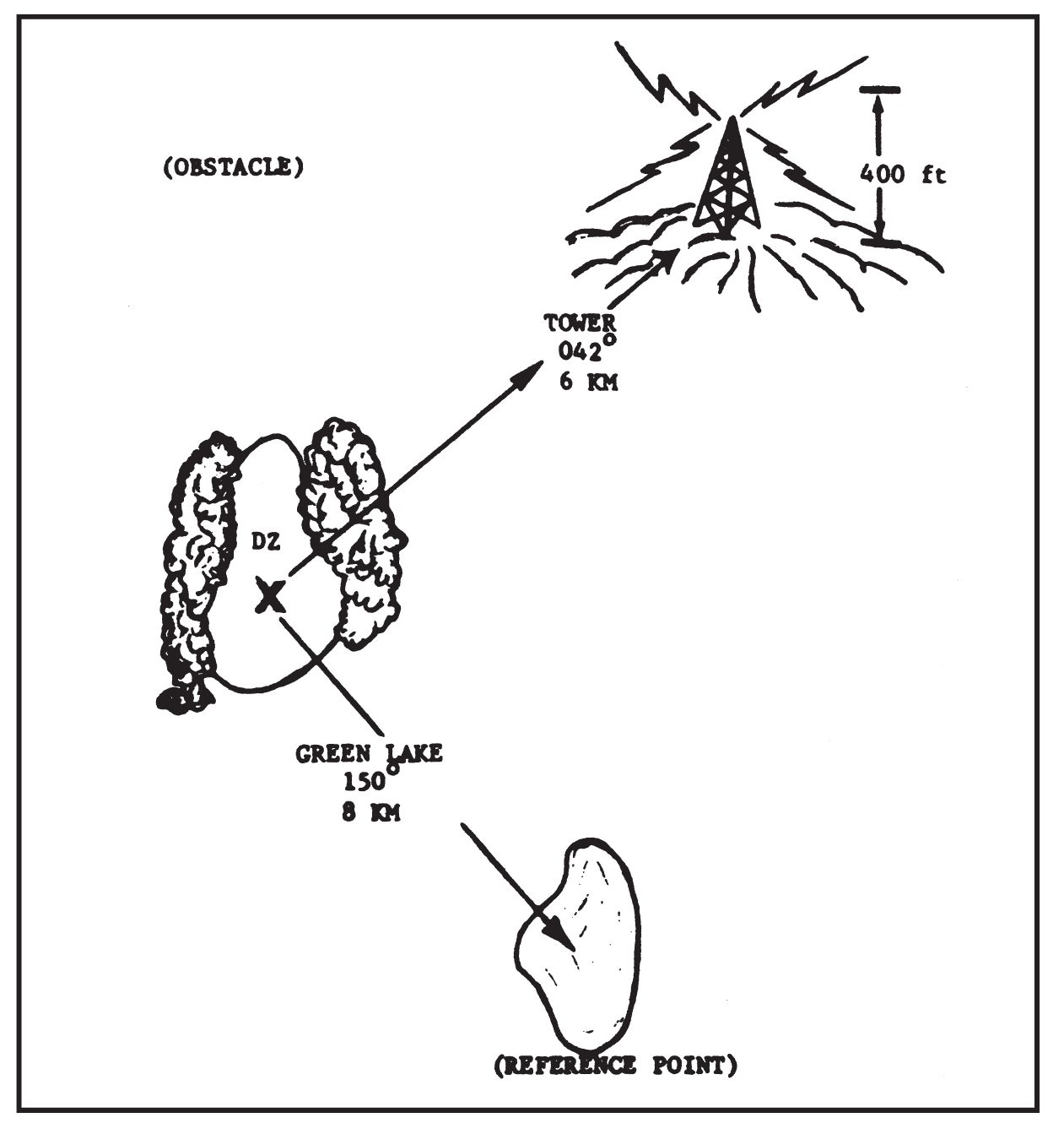
Figure 4. Reporting obstacles and reference points.
- Coastlines. A coastline with breaking surf is easily distinguished at night. Mouths of rivers over 50 yards wide, sharp uprisings, and inlets are excellent guides for both day and night.
- Rivers and canals. Wooded banks reduce reflections, but rivers more than 30 yards wide are visible from the air. Canals are easily recognizable from their straight banks and uniform width. Small streams are not discernible at night.
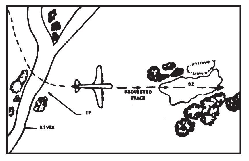
Figure 5. Relationship between IP and requested track.
- Lakes. Lakes at least one-half mile (1 kilometer) square give good light reflection.
- Forest and woodlands. Forested areas at least one-half mile square with clearly defined boundaries of unmistakable shape.
- Major roads and highways. Straight stretches of main roads with one or more intersections. For night recognition, dark surfaced roads are not desirable as IPs although when the roads are wet, reflection from moonlight is visible.
IV. MARKING DROP ZONES:
- Purpose. The purpose of DZ markings is to identify the site for the aircrew and to indicate the point over which the personnel and/or cargo should be released (release point). The procedures for marking DZs are determined prior to infiltration and are included in the SOI.
- Equipment.
- The marking of DZs at night during clandestine operations will normally be only by flashlights. Flashlights manufactured in the country are easily procured by the guerrillas, give adequate directional lighting when properly held, and are not incriminating when found by the security forces on the person of a member of the resistance force. In rare instances other possible lighting devices such as flares, flarepots, fuses, or small wood fires may be used.
- For daylight operations a satisfactory method is the use of issued Panel Marking Set AP-50 or VS-16. If issued panels are not available, sheets, strips of colored cloth or other substitutes may be issued as long as there is a sharp contrast with the background. Smoke signals, either smoke grenade or simple smudge fires, greatly assist the aircrew in sighting the DZ markings on the approach run.
- The use of electronic homing devices permits the conduct of reception operations during conditions of low visibility. Such devices normally are used in conjunction with visual marking systems.
- Computation of Release Point. The release point must be determined to insure delivery of personnel and/or cargo within the usable limits of the DZ. Computation of the release point involves the following factors (Figure 6).
- Personnel from low velocity cargo drops.
- Dispersion. Dispersion is the length of the pattern formed by the exit of the parachutists and/or cargo containers (Figure 2). The desired point of impact for the first parachutist/container depends upon the calculated dispersion.
- Wind drift. This is the horizontal distance traveled from the point of exit to the point of landing as a result of wind conditions. The release point is located an appropriate distance upwind from the desired impact point. To determine the amount of drift, use the following formulas:
- For personnel using the T-10 parachute: Drift (meters) = altitude (hundred of feet) × wind velocity (knots) × 4.1 (constant factor).
- For all other low velocity parachute drops: Same as 1 above, however, substitute a constant factor of 2.6 for 4.1.
NOTE: Where no mechanical wind velocity indicator is available, the approximate velocity can be determined by dropping bits of paper, leaves, dry grass, or dust from the shoulder and pointing to the dry place where they land. The estimated angle in degrees formed by the arm with the body, divided by 4, equals wind velocity.
- Forward throw. This is the horizontal distance traveled by the parachutist or cargo container between the point of exit and the opening of the parachute. This factor, combined with reaction time of personnel in the aircraft, is compensated for by moving the release point an additional 100 meters in the direction of the aircraft approach (Figure 6).
- High velocity and free-drops. Due to their rapid rate of descent, high velocity and free-drop loads are not materially affected by wind conditions. Otherwise, the factors of dispersion and forward throw are generally similar to those for personnel and low velocity drops and are compensated for in the same manner.
- Personnel from low velocity cargo drops.
- Methods of Release Point Marking. There are two methods for marking the DZ release point. The principal difference between the two is the method of providing identification. The marking systems described below are designed primarily for operational drops executed at an absolute altitude of 600 feet (185 meters). Training jumps executed at an absolute altitude of 1,250 feet (383 meters) require a modification of the marking systems.
- Training jumps conducted at an absolute altitude of 1,250 feet (385 meters) require the use of a flank panel or light placed 200 meters to the left of the release point markings. The configuration of present cargo and troop carrying aircraft prevents the pilot from seeing the markings after approaching within approximately one (1) mile of the DZ while flying at 1,250 feet (385 meters) absolute altitude. From this point on, the pilot must depend on flying the proper track in order to pass over the release point. The flank marker serves to indicate when the aircraft is over the release point and the exact moment the drop should be executed. Operational drops executed at 600 feet (185 meters) absolute altitude do not require the flank panel because the pilot does not lose sight of the markings as he approaches the DZ. (See Figure 7.)
- Operational personnel drops or supply drops within a GWOA will normally be executed at altitudes between 600-800 feet for personnel and 400-600 feet for supplies. Release point markings are different numbers of lights with different configurations for each 24-hour period. The exact number of lights and the exact configuration is determined by the detachment SOI. (See Figure 8.)
- Placement of Markings.
- Markings must be clearly visible to the pilot of the approaching aircraft. As a guide, markings must have a clearance of at least 500 yards (460 meters) from a 100-foot (30 meter) mark (Figure 9).
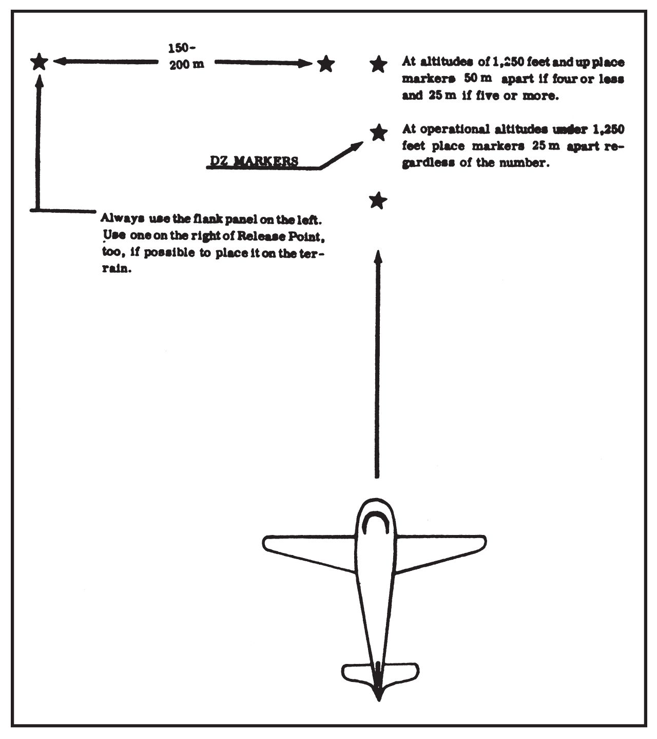
Figure 7. Methods of release point marking.
- Additionally, precautions must be taken to insure that the markings can be seen only from the direction of the aircraft approach. Flashlights may be equipped with simple hoods or shields and aimed toward the flight path. Fires or improvised flares are screened on three sides or placed in pits with sides sloping toward the direction of aircraft approach.
- When panels are used for daylight markings of DZs, they are positioned at an angle of approximately 45° from the horizontal to present the maximum surface toward the approaching aircraft (Figure 10).
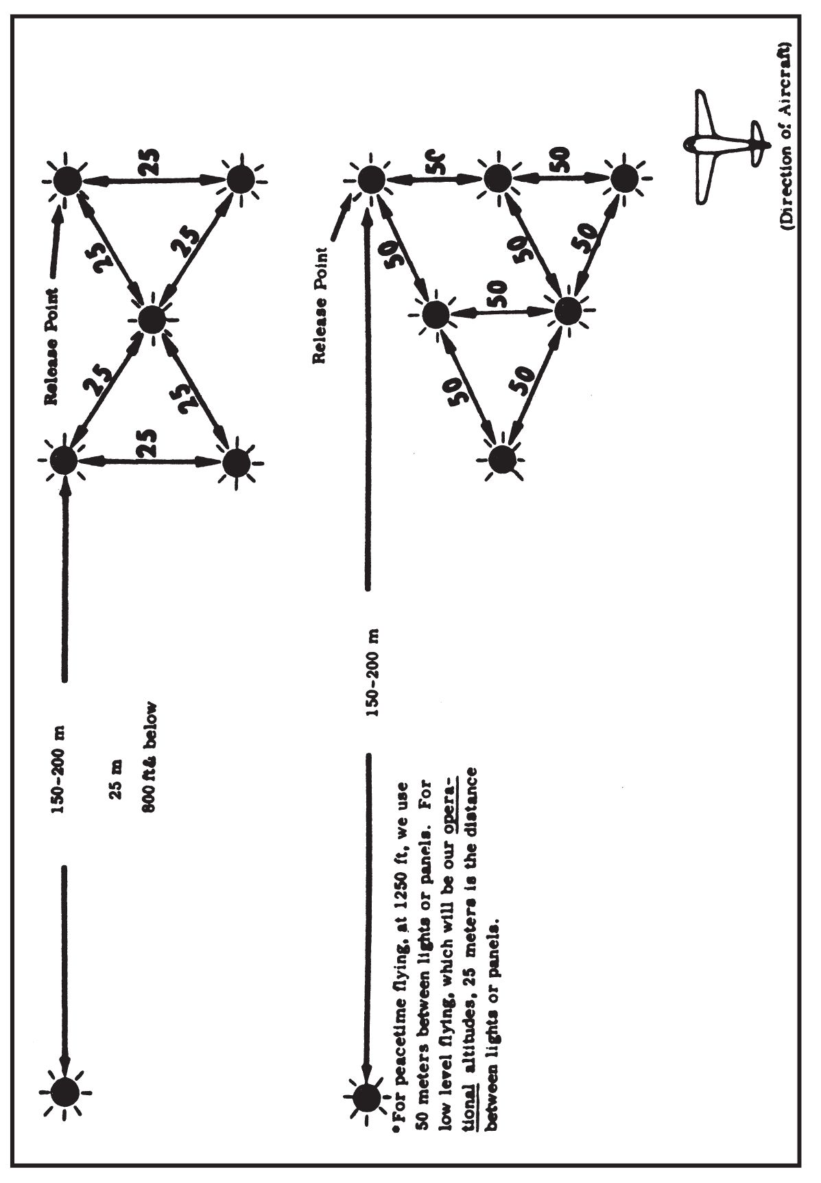
Figure 8. Sample DZ Markings (Distinctive Configuration, not necessarily a letter).
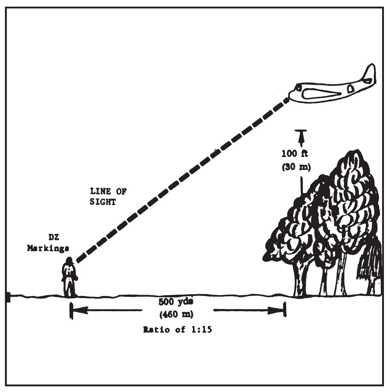
Figure 9. Placement of DZ Markings.
- Markings must be clearly visible to the pilot of the approaching aircraft. As a guide, markings must have a clearance of at least 500 yards (460 meters) from a 100-foot (30 meter) mark (Figure 9).

V. RECEPTION COMMITTEES:
- a. General. A reception committee is formed to control the drop zone or landing area. The reception committee can be anyone who is capable of performing the following duties. A permanent committee for each unit provides the best results, eliminating the need to cross train every one to be capable of this mission. However, training in depth should be accomplished to insure that losses of key personnel will not adversely affect the operation of the group as a whole.
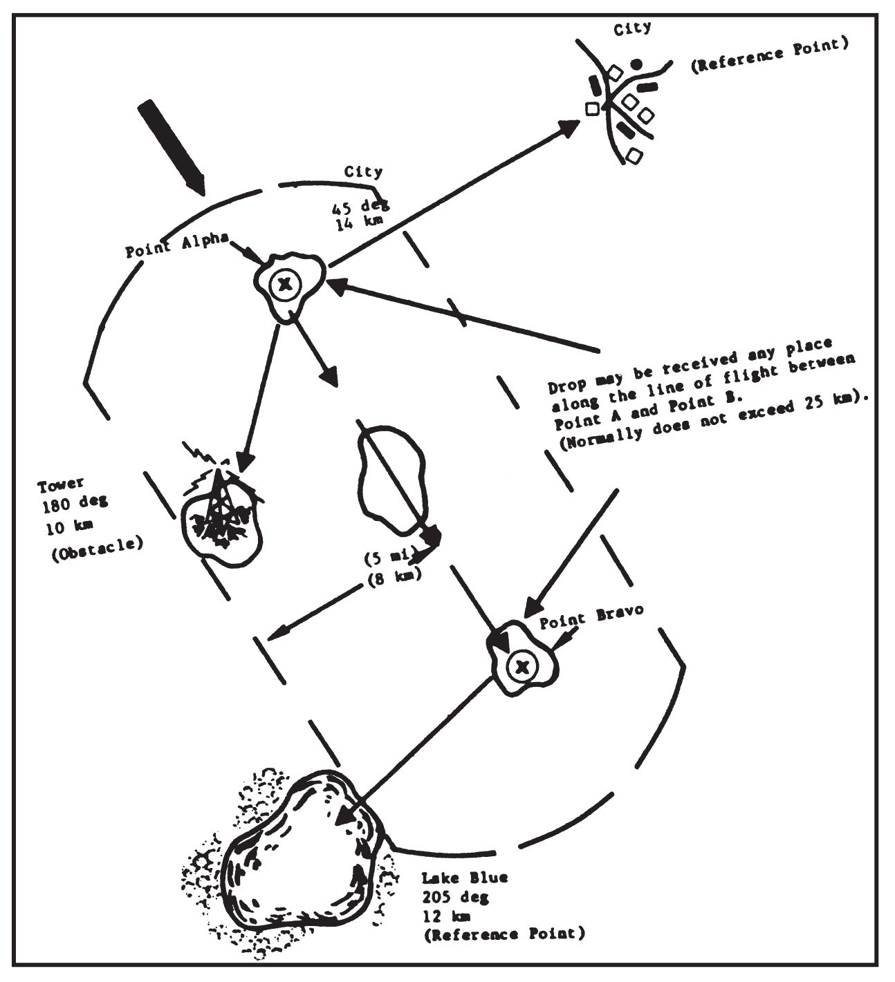
Figure 10. Obstacles and Reference Point (Area DZ).
- Provide security for the reception operation.
- Emplace DZ markings and air ground identification equipment.
- Maintain surveillance of the site prior to and following the reception operation.
- Recover and dispose of incoming personnel and/or cargo.
- Provide for dispatch of personnel and/or cargo in evacuation operations.
- Provide for sterilization of the site (when secrecy is possible and desirable only).
- c. Composition. The reception committee is normally organized into five parties. The composition and functions of the five parties are as follows:
- Command party.
- Controls and coordinates the actions of all reception committee components.
- Includes the reception committee leader (RCL) and communications personnel, consisting of messengers and radio operators.
- Provides medical support, to include litter bearers, during personnel drops.
- Marking party.
- Operates the reception site marking system, using one man for each marker.
- The marking party must be well rehearsed. Improperly placed or improperly operated markings may cause an aborting of the mission.
- Security party.
- Insures that unfriendly elements do not interfere with the conduct of the operation.
- Consists normally of inner and outer security elements.
- The inner security element is positioned in the Immediate vicinity of the site and is prepared to fight delaying or holding actions.
- The outer security element consists of outposts established along approaches to the area. They may prepare ambushes and road blocks to prevent enemy movement toward the site.
- The security party may be supplemented by auxiliaries. These are generally used to maintain surveillance of enemy activities and keep the security party informed of hostile movements.
- Provides march security for moves between the reception site and the destination of the cargo or infiltrated personnel.
- Recovery party.
- Recovers cargo and aerial delivery equipment from the DZ. Unloads aircraft or landing craft.
- For aerial delivery operations the recovery party should consist of at least one man for each parachutist or cargo container. For such operations, the recovery party is usually dispersed along the length of the anticipated Impact area. The members spot each parachute as it descends and move to the landing point. They then recover all parachute equipment and cargo, moving to a predetermined assembly area with the infiltrated personnel or equipment.
- The recovery party is normally responsible for sterilizing the reception site to insure that all traces of the operation are removed when secrecy is possible and desired.
- Transport party.
- Moves items received to distribution points or caches.
- May consist of part, or all, of the members comprising the command, marking, and recovery parties.
- Uses available means of transportation such as pack animals and wagons.
- Command party.
VI. LANDING ZONES (LAND)
- General. The same general considerations applicable to DZ selections apply to the selection of LZs. However, site size, approach features and security are far more important.
- Selection Criteria.
- Desirable terrain features:
- LZs should be located in flat or rolling terrain.
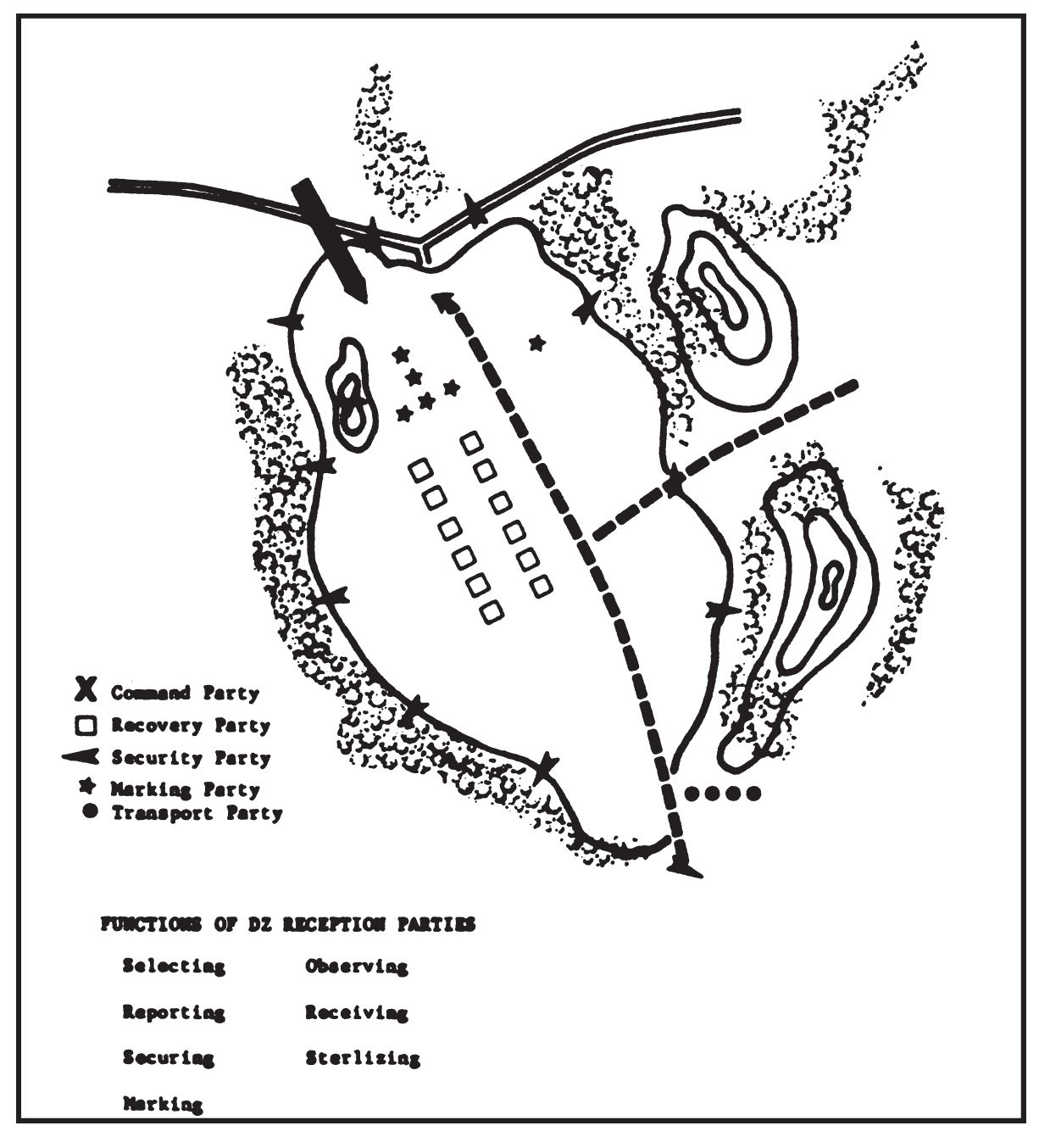
Figure 11. Organization of DZ Reception.
- Level plateaus of sufficient size can be used. Due to decreased air density, landings at higher elevations require Increased minimum LZ dimensions. If the LZ is located in terrain above 4,000 feet (1,220 meters) and/or areas with a very high temperature the minimum lengths should be increased as follows:
- Add 10 percent to minimums for each 1,000 feet (305 meters).
- Add 10 percent to minimum for the altitude for temperatures over 90°F. Add 20 percent for temperatures over 100°F. (38°C).
- Pockets or small valleys completely surrounded by hills are usually unsuitable for landing operations by fixed-wing aircraft.
- Although undesirable, sites with only a single approach can be used. It is mandatory when using such sites that:
- All takeoffs and landings are made upwind.
- There is sufficient clearance at either end of the LZ to permit a level 180° turn to either side within a radius of 3 miles (5 kilometers) for medium aircraft (1 mile for light aircraft).
- LZs should be located in flat or rolling terrain.
- Weather. Prevailing weather in the landing area should be favorable. In particular, there must be a determination of wind direction and velocity, and of conditions restricting visibility such as ground fog, haze, or low-hanging cloud formations.
- Size. The required size of LZs varies according to the aircraft used. Safe operations require the following minimum dimensions (Figures 12 and 13).
- Medium aircraft. 3,000 feet (920 meters) in length and 100 feet (30 meters) in width (150 feet or 45 meters at night).
- Light aircraft. 1,000 feet (305 meters) in length and 40 feet (15 meters) in width (150 feet or 45 meters at night).
- In addition to the basic runway dimensions, and to provide a safety factor, these extra clearances are required.
- A cleared surface capable of supporting the aircraft, extending from each end of the runway, and equal to 10 percent of the runway length.
- A 50-foot (15 meter) strip extending along both sides of the runway and cleared to within three feet of the ground.
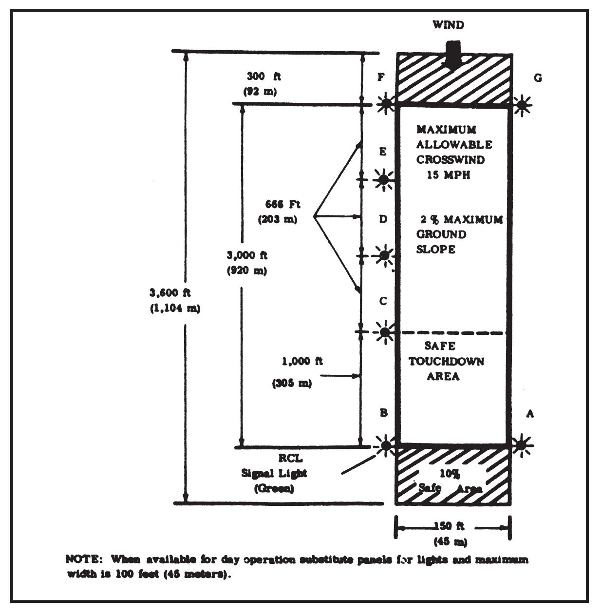
Figure 12. Landing zone (land) medium aircraft (night operations).
- Surface.
- The surface of the LZ must be level and free of obstructions such as ditches, deep ruts, logs, fences, hedges, low shrubbery, rocks larger than a man’s fist or grass over 1 1/2 feet in height.
- The sub-soil must be firm to a depth of 2 feet.
- A surface-containing gravel and small stones, or thin layers of loose sand over a firm layer of sub-soil is acceptable. Plowed fields or fields containing crops over 1 1/2 feet in height should not be used.
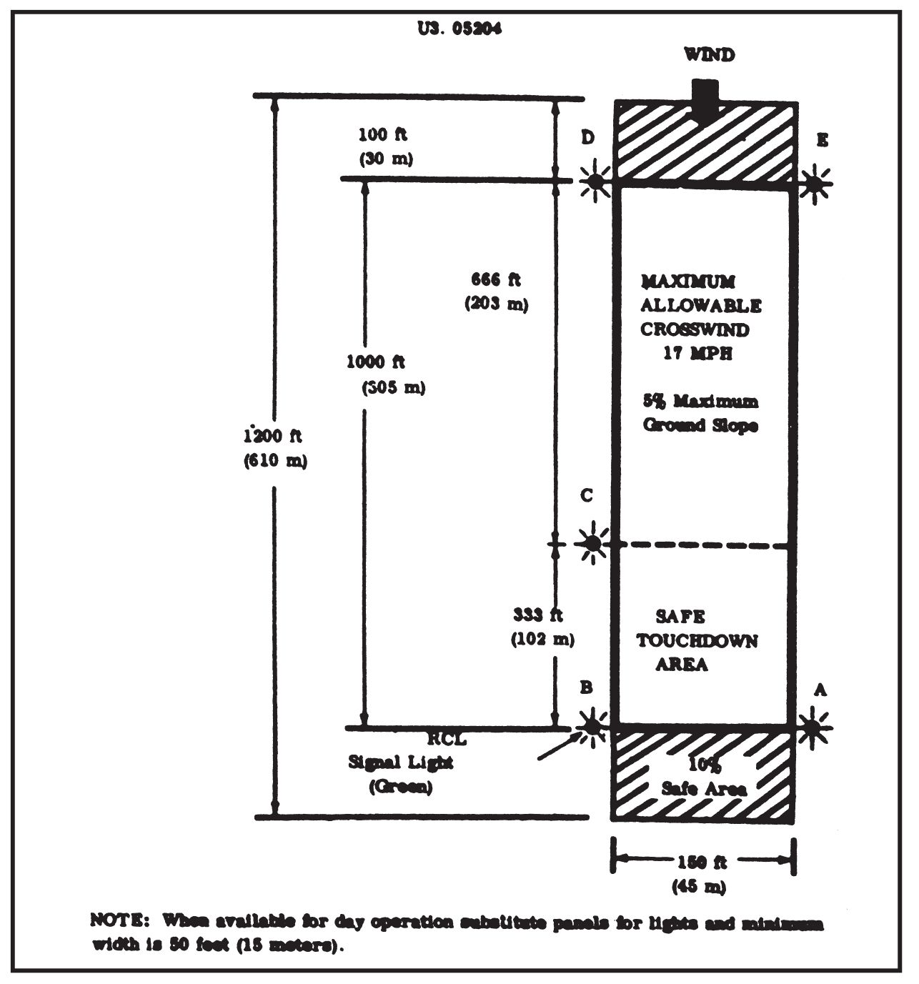
Figure 13. Landing zone (land) light aircraft (night operations).
- As with DZs surfaces that are not desirable in summer may be ideal In winter. Ice with a thickness of 2 feet (61 centimeters) will support a medium aircraft. Unless the aircraft is equipped for snow landing, snow in excess of 4 inches (11 centimeters) must be packed or removed from the landing strip.
- The surface gradient of the LZ should not exceed 2 percent.
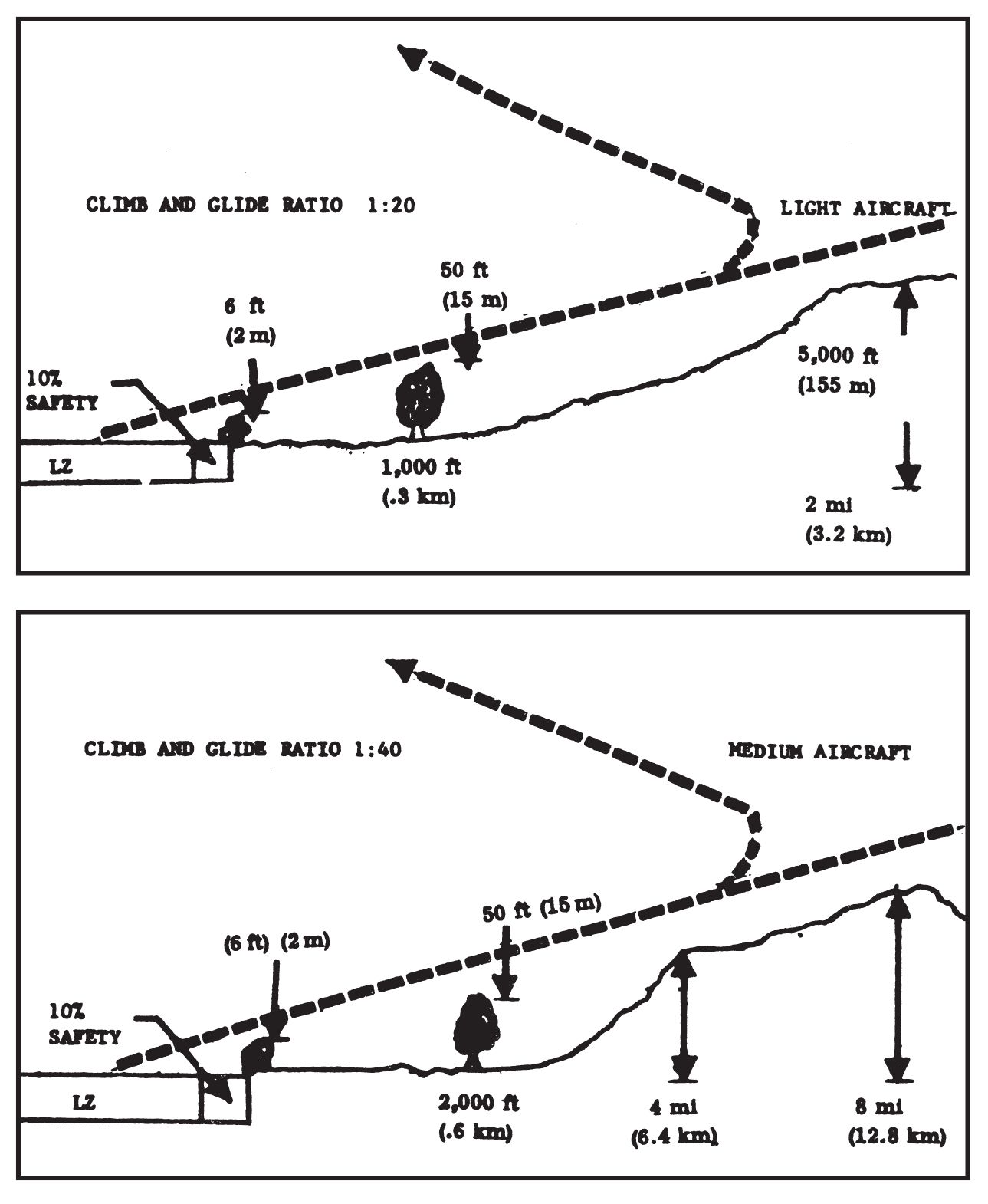
- Approach and takeoff clearance. The approach and takeoff clearances are based on the glide-climb characteristics of the aircraft. For medium aircraft the glide-climb ration is 1 to 40; that is, 1 foot of gain or loss of altitude for every 40 feet of horizontal distance traveled. The ration for light aircraft is 1 to 20. As a further precaution, any obstructions in approach and departure lanes must conform to the following specifications (Figure 14).
- An obstruction higher than 6 feet (2 meters) is not permissible at or near either end of the LZ.
- A 50-foot (15 meters) obstruction may not be nearer than 2,000 feet (610 meters) for medium aircraft, or 1,000 feet (305 meters) for light aircraft.
- A 500-foot (155 meter) obstruction may not be nearer than 4 miles (617 kilometers) for medium aircraft or 2 miles (305 meters) for light aircraft.
- Hills of 1,000 (305 meters) feet or more above LZ altitude may not be nearer than 8 miles (13 kilometers) from the landing sons for medium aircraft.
- The heights of the obstacles are computed from the level of the landing strip. Where land falls away from the LZ, objects of considerable height may be ignored provided they do not cut the line of ascent or descent. This condition exists more often in mountainous terrain where plateaus are selected for LZs.
- Desirable terrain features:
- Markings.
- For night operations lights are used for marking LZs; during day-light, panels are used. When flashlights are used, they should be hand-held for directional control and guidance.
- The pattern outlining the limits of the runway consists of five or seven marker stations (Figures 11 and 12). Stations “A” and “B” mark the downwind end of the LZ and are positioned to provide for the safety factors previously mentioned. These stations represent the initial point at which the aircraft should touch the ground. Station “C” indicates the very last point at which the aircraft can touch down and complete a safe landing.
- A signal station manned by the RCL (a member of the operational detachment) is incorporated into light station “B” at the approach on downwind end of the LZ (Figures 11 and 12). For night operations, (the signal light operations,) a distinctive panel or colored smoke, located approximately 15 meters to the left of station “B” (RCL), is used for recognition.
- Conduct of Operations.
- The LZ markings are normally displayed 2 minutes before the arrival time indicated in the mission confirmation message. The markings remain displayed for a period of 4 minutes or until the aircraft completes landing roll after touchdown.
- Identification is accomplished by:
- The aircraft arriving at the proper time on prearranged track.
- The reception committee leader flashing or displaying the proper code signal.
- Landing direction is indicated by:
- The RCL signal control light (station “B”) and marker “A” which are always on the approach or downwind end of the runway.
- The row of markers which are always on the left side of the landing aircraft.
- The pilot usually attempts to land straight-in on the initial approach. When this is not possible, a modified landing pattern is flown using a minimum of altitude for security reasons. Two minutes before target time the RCL causes all lights of the LZ pattern to be turned on and aimed like a pistol in the direction of the aircraft’s approach track. The RCL (station “B”) also flashes the code of the day continuously with the green control light in the direction of expected aircraft approach. Upon arrival in the area (within 15° to either side of the approach track and below 1,500 feet (460 meters)), the LZ marking personnel follow the aircraft with all lights when it arrives in the area. When the RCL determines that the aircraft is on its final approach, he will cease flashing the code of the day and aim a solid light in the direction of the landing aircraft. The solid light provides a more positive pattern perspective for the pilot during landing. If a “go around” is required, all lights follow the aircraft until it is on the ground. All lights continue to follow the aircraft during touchdown and until it passes each respective light station.
- Landings are not normally made under the following conditions:
- Lack of or improper identification received from the LZ.
- An abort signal given by the RCL, e.g., causing the LZ lights to be extinguished.
- Any existing condition that, in the opinion of the pilot, makes it unsafe to land.
- After the aircraft passes the RCL position at touchdown and completes its landing roll and a right turn, the RCL takes a position midway between stations “A” and “B” and shines a solid light in the direction of the taxiing aircraft. This is the guide light for the pilot who will taxi the aircraft back to take-off position. The RCL controls the aircraft with his light. If the RCL desires the aircraft to continue to taxi, he will flash a solid light in the direction of the aircraft. After off-loading and/or on-loading is complete and the aircraft is ready for takeoff, the RCL moves to a vantage point forward and to the left of the pilot, causes the LZ lights to be illuminated, and flashes his light toward the nose of the aircraft as the signal for takeoff. The RCL exercises caution so that his light does not blind the pilot.
- To eliminate confusion and insure expeditious handling, personnel and/or cargo to be evacuated wait for unloading of incoming personnel and/or cargo.
- When all evacuating personnel are loaded and members of the reception committee are clear of the aircraft, the pilot is given a go signal by the RCL. LZ markings are removed as soon as the aircraft is airborne.
VII. REPORTING LANDING ZONES.
The minimum LZ data required is:
- Code Name. Extracted from SOI.
- Location. Complete military grid coordinates of center of LZ.
- Long Axis. Magnetic azimuth of long axis of runway. It also indicates probable direction of landing approach based on prevailing winds.
- Description. Type of surface, length, and width of runway.
- Open Quadrant. Measured from center of LZ and reported as series of magnetic azimuths. Open Quadrant indicates acceptable aircraft approaches.
- Track. Magnetic azimuth of desired aircraft approach.
- Obstacles. Reported by description, magnetic azimuth, and distance from center of LZ.
- Reference Point. Reported same as obstacles.
- Date. Time mission requested.
- Items Requested. Items to be evacuated.
VIII. LANDING ZONES FOR ROTARY-WING AIRCRAFT:
- General.
- Within their range limitations, helicopters provide an excellent means of evacuation. Their advantages include the ability to:
- Ascend and descend almost vertically.
- Land on relatively small plots of ground.
- Hover nearly motionless, and take on or discharge personnel and cargo without landing.
- Fly safely and efficiently at low altitudes.
- Some unfavorable characteristics of helicopters are:
- They compromise secrecy by engine and rotor noise and by dust.
- The difficulty—sometimes impossibility—of operating when icing and/or high, gusty winds prevail.
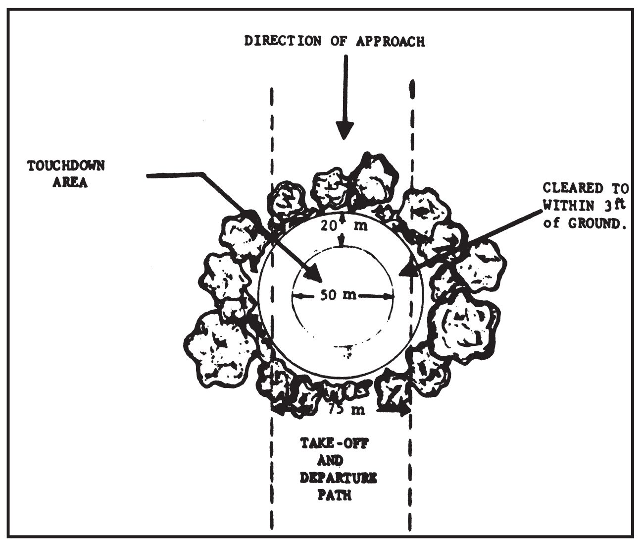
Figure 15. Landing Zone for Rotary-Wing Aircraft.
- The reduction of lifting ability during changes of atmospheric conditions.
- For the maximum effective use of helicopters, LZs should be located to have landings and takeoffs into the wind.
- During night operations, helicopters usually must land to transfer personnel and/or cargo.
- A decrease in normal air density limits the helicopter payload and requires lengthened running distances for landing and takeoff. Air density is largely determined by altitude and temperature. Low altitudes and moderate to low temperatures result in increased air density.
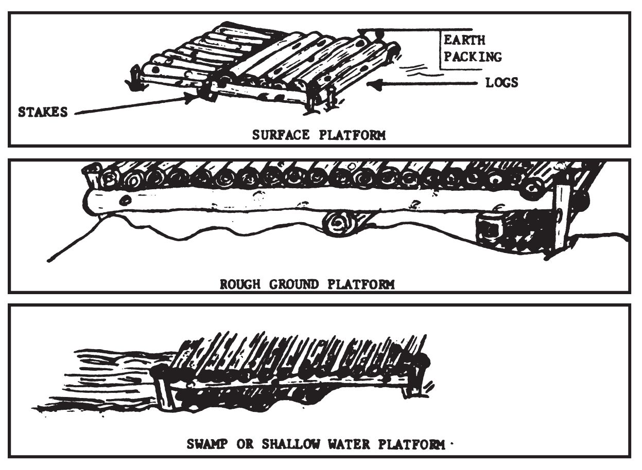
Figure 16. Example of platform landing zones for rotary-wing aircraft.
- Within their range limitations, helicopters provide an excellent means of evacuation. Their advantages include the ability to:
- Size. Under ideal conditions, and provided the necessary clearance for the rotors exists, a helicopter can land on a plot of ground slightly larger than the spread of its landing gear. For night operations, however, a safety factor is allowed with the following criteria as a guide:
- An area of 50 meters in diameter cleared to the ground.
- An area beyond this, surrounding the cleared area, 20 meters wide and cleared to within 3 feet of the ground.
- The completed LZ is thus a minimum of 90 meters in diameter (Figure 15).
- Surface.
- The surface should be relatively level and free of obstructions such as rocks, logs, tall grass, ditches, and fences.
- The maximum ground slope permitted is 15 percent.
- The ground must be firm enough to support the aircraft.
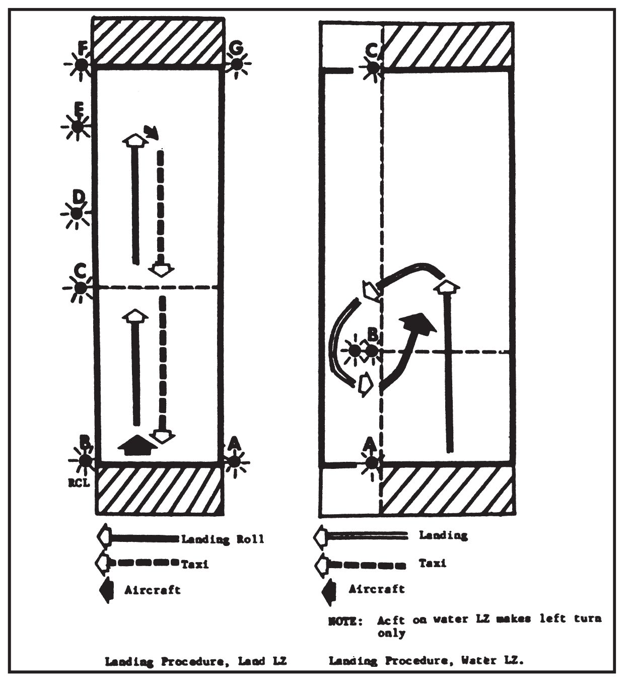
Figure 17.
- Heavy dust or loose snow conditions interfere with the vision of the pilot Just before touchdown. This effect can be reduced by clearing, wetting down, or using improvised mats.
- Landing pads may be prepared on swamp or marsh areas by building platforms of locally available materials (Figure 16). Such LZs are normally used for daylight operations only. The size of the clearing for this type of LZ is the same as b above, with the following additional requirements for the platform:
IX. LANDING ZONES (WATER)
- a. Criteria for selection of water LZs:
- Size. For medium amphibious or seaplane-type aircraft, the required length is 4,000 feet (1,220 meters) with a minimum width of 1,500 feet (460 meters). For light aircraft, the required length is 2,000 feet (615 meters) long and 500 feet (155 meters) wide. As with land LZs, and additional safe area equal to 10 percent of the airstrip length is required on each end. (Figure 18.)
- Surface. Minimum water depth is 6 feet (2 meters). The entire landing zone must be free of obstructions such as boulders, rock ledges, shoals, waterlogged boats, or sunken pilings within 6 feet of the surface, and the surface must be cleared of all floating objects such as logs, debris, or moored craft.
- Wind.
- Wind velocity must not exceed 20 knots for sheltered water or 10 knots in semi-sheltered water.
- In a wind of 8 knots or less, the landing heading may vary up to 15 degrees from the wind direction. Where the surface winds exceed 8 knots the aircraft must land into the wind. No landing may be made in winds in excess of 20 knots. If a downwind landing or takeoff is absolutely required, this is made directly downwind.
- Surface swells must not exceed 1 foot in height and the windwave not more than 3 feet. The combination of swell and windwave must not exceed 3 feet in height when all swells and windwaves are in phase.
- Tide. The state of the tide should have no bearing on the suitability of the landing area.
- Water/air temperature. Due to the danger of icing, water and air temperatures must conform to the following minimums:
Water temperature Air temperature Salt water −18°F. (−8°C.) −26°F. (−3°C.) Fresh water −35°F. (−2°C.) −35°F. (−2°C.) Brackish water −30°F. (−1°C.) −35°F. (−2°C.) 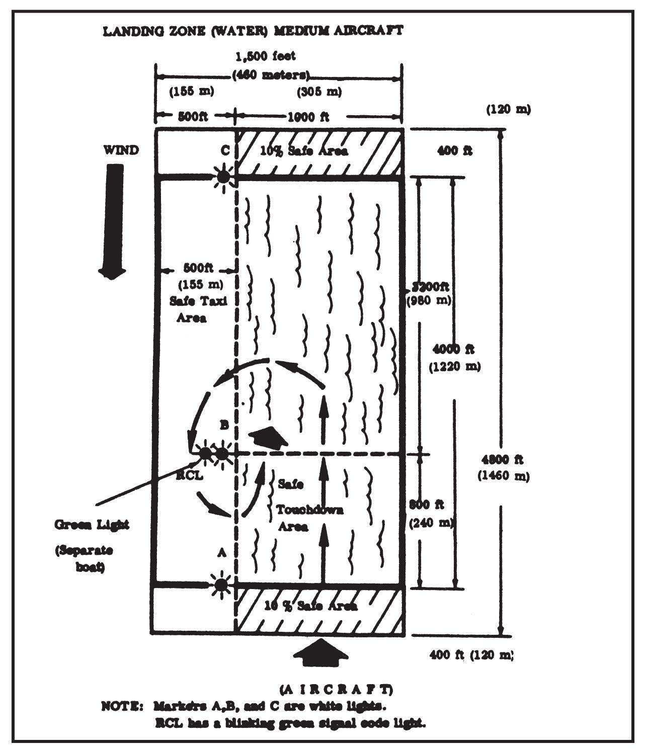
Figure 18. Landing Zone (water) medium aircraft (night operations).
- Approach and takeoff clearances. Water landing zones require approach/takeoff clearances identical to those of land LZs and are based on the same glide/climb ratios.
- c. Marking and identification of water landing zones.
- Depending upon visibility, lights or panels may be used to mark water LZs.
- The normal method of marking water LZs is to align three marker stations along the left edge of the landing strip. Station “A” is positioned at the downwind end of the strip and indicates the desired touchdown point. Station “B” marks the last point at which the aircraft can touch down and complete a safe landing. Station “B” is also the location of the RCL and the pickup point. Station “C” marks the upwind extreme of the landing area. At night, stations “A,” “B,” and “C” are marked by white lights. The RCL signal light is green.
- An alternate method is to use a single marker station, marked at night with a steady light in addition to the signal of recognition light. This station is located to allow a clear approach and takeoff in any direction. The pilot is responsible for selecting the landing track and may touchdown on any track 1,000 feet (305 meters) from the marker station. Following pickup, the aircraft taxis back to the 2,000-foot (610 meters) circle in preparation for takeoff. (Figure 19.)
- d. Conduct of operations for water LZs:
- Before the landing operation, the LZ is carefully cleared of all floating debris. Also, the marker stations are properly aligned and anchored to prevent drifting. In deep or rough water, improvised sea anchors may be used.
- The procedure for displaying the LZ markings and identification is the same as for operations on land LZs.
- Personnel and/or cargo to be evacuated are positioned in the RCL boat. Following the landing run, the aircraft turns to the left and taxis back to the vicinity of the RCL boat to make the pickup. The RCL indicates his position by shining the signal light in the direction of the aircraft and continues to shine his light until the pickup is completed. Care must be taken not to blind the aircrew with this light and it should not be aimed directly into the cockpit.
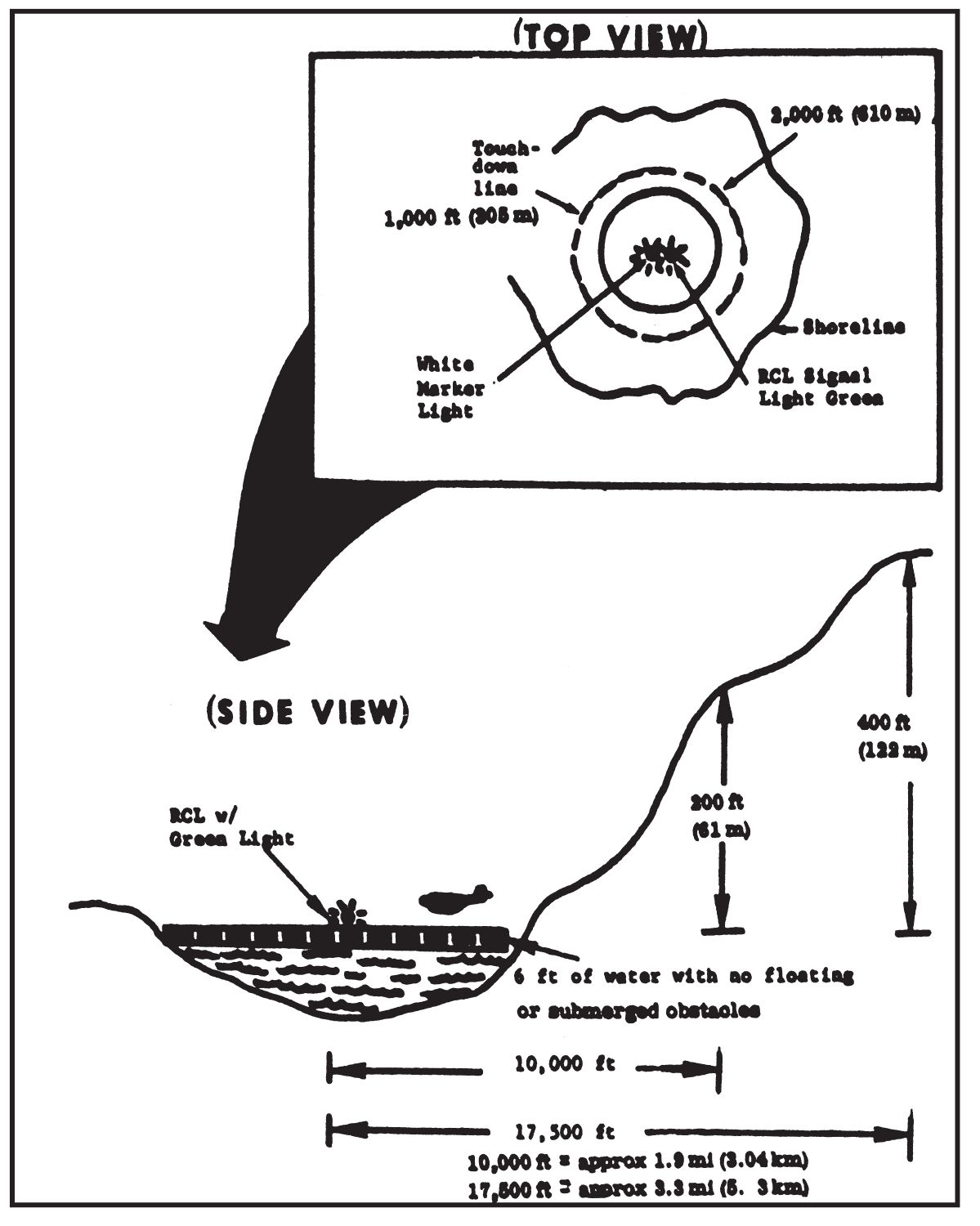
Figure 19. One light water landing zone (night).
- The RCL boat remains stationary during pickup operations. The aircraft taxis to within 50 to 100 feet (15 or 30 meters) of the RCL boat, playing out a dragline from the left rear door. The dragline is approximately 150 feet (45 meters) in length and has three life jackets attached; one close to the aircraft, a second at midpoint, and the third on the extreme end of the line. The life jackets have small marker lights attached during night operations. The aircraft taxis to the left around the RCL boat, bringing the dragline close enough to be secured. The RCL fastens the line to the boat. Due to the danger of swamping the craft, the RCL does not attempt to pull on the line. Members of the aircrew pull the boat to the door of the aircraft. Should the boat pass the aircraft door and continue toward the front of the aircraft, all personnel in the boat must abandon immediately to avoid being hit by the propeller.
- After pickup, the aircrew is given any information that will aid in the takeoff. Following this, the RCL boat moves a safe distance from the aircraft and signals the pilot “all clear.” At this time, JATO bottles may be used for positive takeoff power. The installation of JATO bottles is time consuming and should not be done unless absolutely necessary.
- Helicopters can land in water without the use of special flotation equipment provided:
- The water depth does not exceed 18 inches.
- There is a firm bottom such as gravel or sand.
- Landing pads can be prepared on mountains or hillsides by cutting and filling. Caution must be exercised to insure there is adequate clearance for the rotors.
- d. Approach/Takeoff.
- There should be at least one path of approach to the LZ measuring 75 meters in width.
- A rotary wing aircraft is considered to have a climb ratio of 1:5 (Figure 20).
- Takeoff and departure from the LZ may be along the same path used for the approach; however, a separate departure path as free from obstacles as the approach path is desired (Figure 20).
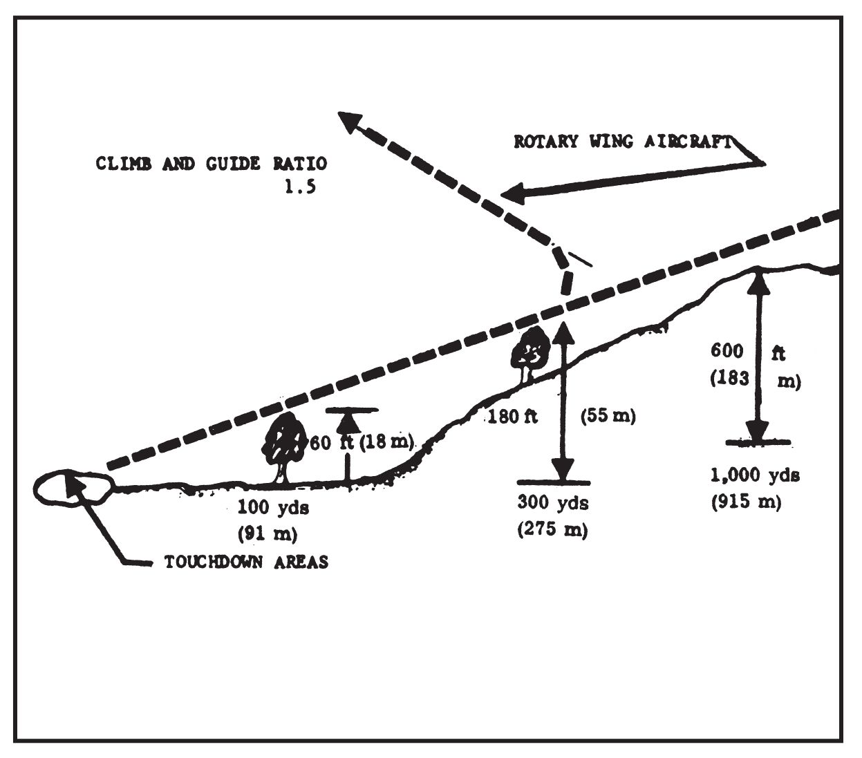
Figure 20. Approaching Takeoff Clearances for Rotary-Wing Aircraft.
- e. Marking.
- LZs for rotary-wing aircraft are marked to:
- Provide identification of the reception committee.
- Indicate direction of wind and/or required direction of approach.
- Delineate the touchdown area.
- Equipment and techniques of marking are similar to those used with fixed-wing DZs, lights or flares at night, smoke and panels in daylight.
- An acceptable method of marking is the “Y” system. This uses four marker stations (Figure 21).
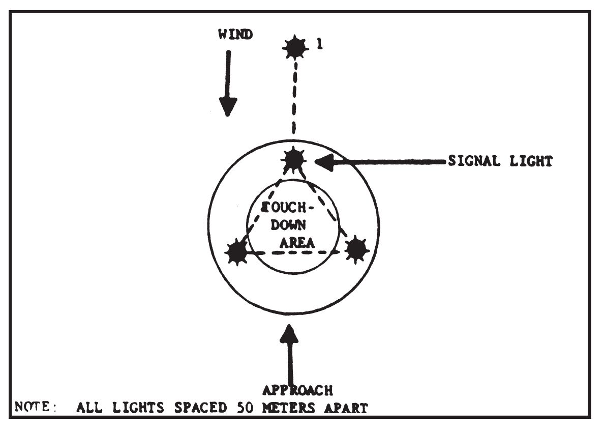
Figure 21. Marking of landing zones for use by rotary-wing aircraft.
TABLE NR. 1. FIXED AND ROTARY WING AIRCRAFT CAPABILITIES.

- LZs for rotary-wing aircraft are marked to: