Chapter 5
Propulsion
All (non-glider) aircraft require powerful, lightweight, efficient propulsion. For medium and small unmanned air vehicles (UAVs), this almost always means some form of propeller-based system. As it is difficult to engineer variable-pitch propellers on the scales required, fixed pitch systems are generally used. Combined with the high costs of developing bespoke prime movers, this means that the designer of small and medium UAVs is generally faced with rather difficult compromises in selecting the appropriate propulsion system from components already available on the market. We have found no concrete solutions: for long-endurance aircraft, we tend toward gasoline-fueled internal combustion (IC) engines with multiple cylinders, via multicylinder engines, multiple engines, or both. For short-endurance systems, especially if low vibration is important, battery-powered electric motors are often preferable, and as battery technology improves, electric propulsion will become more useful for longer endurance systems. Here we consider both these forms of propulsion in various configurations and also hybrid systems where both IC engines and electric motors are fitted to a single airframe.
In sizing and assessing propulsion systems, we rely on various sets of results we have obtained from a dedicated engine/propeller test facility we have built and also the first-rate data produced at the University of Illinois at Urbana-Champaign (UIUC) by Brandt and Selig [12]. It has been our experience that it is wisest to actually measure static and dynamic thrust, fuel, and battery consumption, and so on, for ourselves whenever possible. Dedicated test cells also provide an ideal place for setting up and running in new engines in controlled conditions, see Figures 5.1 and 5.2. We deal with the range of engines and motors we have direct experience with in the following sections. See also Section 11.6 for various expressions we use in estimating likely propeller and engine sizes.

Figure 5.1 UAV engine/electric motor/propeller test cell. Note the starter generator on the engine behind the four-bladed propeller.
5.1 Liquid-Fueled IC Engines
Liquid-fueled engines available for small and medium-sized UAVs are essentially two- or four-stroke gasoline, methanol, or diesel units. Major considerations are the availability, weight, cost, power, and efficiency. Few UAV programs can afford to develop their own prime movers, so generally one is forced to select from those already on the market. For example, for airframes in the 10–50 kg maximum take-off weight (MTOW) range, there are probably fewer than 20 suitable spark ignition engines and almost no widely available diesel engines (though developments of new UAV engines are under way in many countries). For UAVs of less than 10 kg MTOW, the widest selection of IC engines comprise glow-plug ignition running on methanol-based fuels. These are cheap and powerful but tend to have poor fuel consumption. In our experience, the simplest way to get reasonable economy is via four-stroke gasoline systems using conventional carburetors or, at higher cost, two-stroke gasoline engines with manifold fuel injection. The latter are more involved but offer the prospect of improved fuel management, though a well set up four-stroke carburetor engine tuned to operate at a fixed cruise speed/rpm can be reasonably competitive. The conventional poppet valve gear on most four-stroke engines can, however, be a weakness in such systems, generally requiring adjustment after any extended flight. Figure 5.3 shows typical powers, weights, and estimated static thrusts of IC engine for UAVs in the 2–150 kg MTOW range. Note the relative paucity of data for the larger engine sizes.
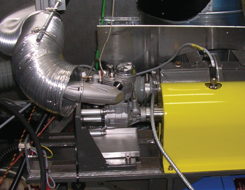
Figure 5.2 UAV engine dynamometer.
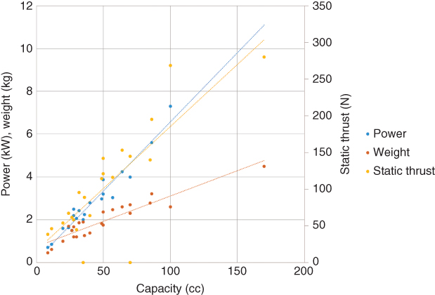
Figure 5.3 Typical maximum powers, weights, and estimated peak static thrusts of engines for UAVs in the 2–150 kg MTOW range.
5.1.1 Glow-plug IC Engines
The IC engines most commonly used in small model aircraft are methanol-fueled glow-plug engines. A vast range of these are cheaply available running two- and four-stroke cycles with capacities ranging from a few cubic centimeters (cc) up to over 100 cc in configurations spanning single cylinder, flat twin, flat four, inline four, and radial combinations with as many as nine cylinders. Even the largest and most complex versions from the best makers typically cost no more than $3500. We have made extensive use of the products manufactured by OS in Japan.1 We find these to be well made and reliable at acceptable cost. In particular, we have flown many hours with their four-stroke flat-twin FT-160 Gemini engines, see Figure 5.4. Typical fuel consumption can, however, be over 1 l/h with this 26.5 cc engine, even though it is a four-stroke design (two-stroke glow-plug engines are even more thirsty). While this is not an issue for the aero-modelers for whom they are designed, it means that for long-endurance UAVs, a significant part of the aircraft take-off weight is fuel when powered by these types of engines.
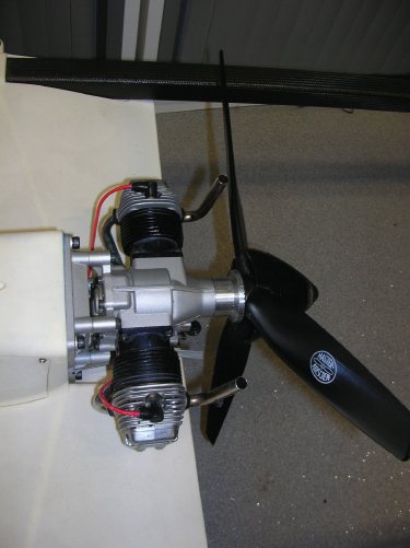
Figure 5.4 OS Gemini FT-160 glow-plug engine in pusher configuration. Note the permanent wiring for glow-plugs.
5.1.2 Spark Ignition Gasoline IC Engines
The primary reason why glow-plug engines are so thirsty for fuel is that there is no control over when ignition takes place in the engine cycle. To overcome this limitation, one must switch to spark ignition systems (or direct injection). The advent of compact, Hall-effect-triggered ignition modules and tiny spark plugs has made spark ignition engines readily available at modest cost, though the need to incorporate a functioning spark plug in the cylinder head limits how small these engines can be. Currently, the smallest OS spark ignition engine is their single-cylinder, 15 cc, two-stroke GT15 engine. If a four-stroke engine is desired, the need to accommodate valve gear as well as the spark plug means that their smallest engine of this type is the 30 cc GF30 (see Figure 5.5). For larger aircraft, we have used either larger single-cylinder engines or flat twin- and flat four-cylinder variants. For added operational redundancy, we currently opt for twin single-cylinder engines for aircraft up to 40 kg MTOW. Above that, multicylinder engines become more appropriate. Figures 5.6, 5.7, and 5.8 show three of our larger UAVs, one with a single twin-cylinder engine and the others with two singles, in the latter cases running two- and four-stroke cycles. We have not tried rotary Wankel engines because of their generally poorer fuel efficiency, though they are available in a range of sizes and may offer lower vibration levels.
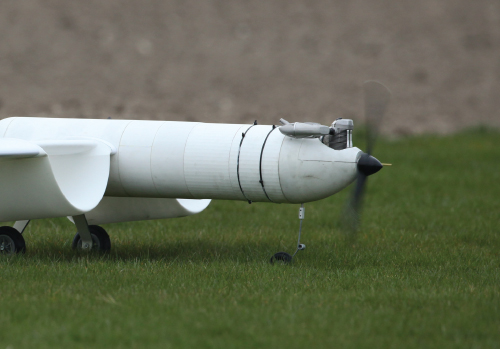
Figure 5.5 OS 30 cc GF30 four-stroke engine installed in a hybrid powered UAV. Note the significant size of the exhaust system.
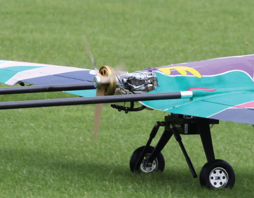
Figure 5.6 Saito 57 cc twin four-stroke engine in pusher configuration. Note the pancake starter generator fitted to this engine.
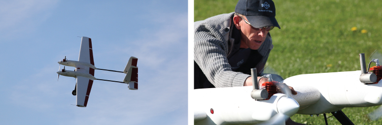
Figure 5.7 Twin 3W-28i CS single-cylinder two-stroke engines fitted to 2Seas UAV. Note again the significant size of the exhaust systems.
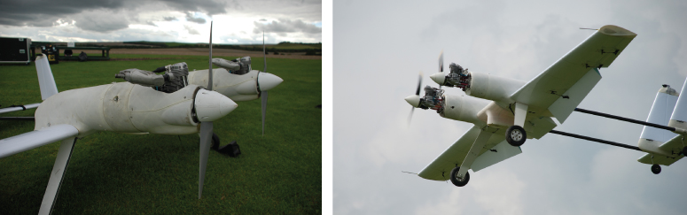
Figure 5.8 Twin OS 40 cc GF40 four-stroke engines installed in SPOTTER UAV, with and without engine cowlings.
The choice between two-stroke and four-stroke spark ignition engines is not an entirely straightforward one. In theory, the two-stroke cycle gives more power at a given rpm because there are twice as many firing pulses at any engine speed. However, the volumetric efficiency of two-stroke cycles is not as well controlled as that of four-stroke cycles, which permit accurate control of valve timings. This tends to make two-stroke engines more thirsty than their four-stroke counterparts and not as powerful as theory would predict, though size for size they are generally lighter as they do not need cam shafts and valve gear. They also have the great benefit of simplicity. Maintaining accurate valve seating in such small engines is a real difficulty with conventional four-stroke systems that use poppet valves: if not regularly maintained, it is very easy to burn exhaust valves and lose compression. To take advantage of two-strokes mechanical simplicity while retaining good fuel efficiency, it is possible to use manifold injection on these engines. The UAV factory UAV28-EFI Turnkey Fuel Injected Engine does this to good effect, although this inevitably sacrifices some of the simplicity of the overall system.2 Alternatively, more sophisticated valve arrangements may be used on four-stroke engines such as those fitted to the RCV DF 35 and DF 70 UAV systems.3 Their rotary valves give high reliability and very good fuel consumption, particularly when combined with manifold fuel injection, although this level of sophistication does not come cheap. At the most extreme end of this spectrum lie engines such as the AE1 developed by Cosworth, which is a direct-injection two-stroke system using compression ignition rather a spark plug, permitting operation of the Diesel as opposed to Otto cycle, with the resulting higher compression ratio and better thermodynamic efficiency. Currently, such systems are not widely available and are extremely expensive when compared to a simple OS two-stroke system, but thermodynamic efficiencies as high as 0.335 kg/kWh have been reported.
5.1.3 IC Engine Testing
As has already been noted, we prefer to test each IC engine we are considering in our own test cells rather than simply relying on manufacturers' data. In the dynamometer cell, seen in Figure 5.1, the basic measurements we take are fuel consumption and torque at varying speeds and throttle settings, often with both gravity-fed and fully pumped fuel lines (a number of small UAV engines will give greater power when used with pressurized fuel lines, while some have built-in fuel pumps). Figure 5.9 shows a typical plot of raw data taken from our dynamometer. We average across the raw data aiming to complete tables such as the one shown in Table 5.1, from which we can then derive the engine power, brake-specific fuel consumption (BSFC), and brake mean effective pressure (BMEP) plots. When combined with the engine mass (including standard exhaust system and ignition system), one can then make like-for-like comparisons between alternative engines. Prior to running tests, we carefully calibrate the torque sensor with a weighted balance bar and also the throttle servo to ensure that 0% and 100% throttle openings are correctly achieved when set by the control system of the dynamometer.
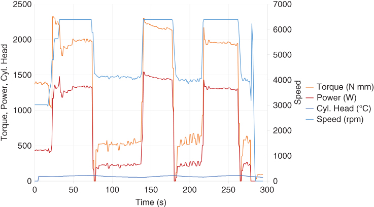
Figure 5.9 Raw performance data taken from an engine under test in our dynamometer.
Table 5.1 Typical liquid-fueled IC engine test recording table (maximum rpms are of course engine-dependent)
| Fueling type | 40% Throttle | 60% Throttle | 80% Throttle | 100% Throttle | ||||
| Speed (rpm) | Fuel consumption (l/min) | Torque (Nm) | Fuel consumption (l/min) | Torque (Nm) | Fuel consumption (l/min) | Torque (Nm) | Fuel consumption (l/min) | Torque (Nm) |
| 1500 | ||||||||
| … | ||||||||
| 4500 | 0.44 | 0.45 | 0.51 | 0.170 | 0.57 | 0.93 | 0.69 | 1.22 |
| … | ||||||||
| 8000 | ||||||||
| 8500 | ||||||||
Note that all engine test results are subject to variability depending on the engine set up and wear, test cell operating conditions, and any losses due to induction, exhaust, or coupling factors. If precise details of the tests carried out are not available, such results should be treated with caution during the design phase.
BMEP, which is given from torque  by BMEP
 (
( for two-stroke and
  for four-stroke engines), allows a comparison of the quality of the combustion system between engines of differing sizes and between different cycle types. Table 5.2 shows typical values of BMEP for a range of engine types, higher values of BMEP being better: the values achieved by the supercharged Rolls-Royce Merlin were clearly outstanding. In the end, however, it is usually BSFC and power-to-weight ratios that drive design calculations and engine selection.
Table 5.2 Typical IC engine BMEP values taken from various sources
| Engine type | BMEP at peak power (MPa) |
| Naturally aspirated spark-ignition engines | 0.85–1.05 |
| Boosted spark ignition engines | 1.25–1.7 |
| Naturally aspirated four-stroke diesels | 0.7–0.9 |
| Boosted automotive four-stroke diesels | 1.4–1.8 |
| Very large low speed diesels | 1.9 |
| Napier Sabre 7 (3055 HP at 3850 rpm) | 1.94 |
| Rolls-Royce Merlin 130/131 (2030 HP at 2900 rpm) | 2.31 |
| Pratt& Whitney R-4360 Wasp Major (3600 HP at 2700 rpm) | 1.72 |
| Typical small aero-modeler-based four-stroke UAV gasoline engines | 0.85–1.15 |
| Typical small aero-modeler-based two-stroke UAV gasoline engines | 0.6–0.9 |
Note that BMEP values are typically 10–15% higher at the maximum torque speed as compared to maximum power speed and also that by assuming a BMEP of 1.0 MPa, it is possible to estimate the likely achievable peak power of a four-stroke UAV engine at a range of engine speeds.
Having completed a dynamometer test, we then run engine and propeller combinations in our dedicated wind tunnel system, also shown in Figure 5.1. This allows static thrust and thrust at varying air speeds to be recorded along with the reaction torque experienced at the engine mountings. The test cell also allows fuel flow rates to be measured. This allows an assessment of the overall efficiency of the propulsive system. Careful matching of propellers to engines is vital in achieving best performance from such systems. Moreover, the propulsive efficiency of small UAV propellers varies quite widely: the extensive test data collected by UIUC demonstrates this most clearly [12].
5.2 Rare-earth Brushless Electric Motors
While we most often use IC engines for our UAVs, small, powerful brushless electric motors based on rare-earth magnets are now available in a wide range of sizes so there is a much greater choice of units than for IC engines. Obviously, such motors must be supported by battery packs, fuel cells, or on-board generators (hybrid systems). In the world of multi-rotor UAVs, they are extremely widely used, and many commercial camera-carrying systems adopt these technologies. They are smooth, powerful, and highly reliable devices since they involve so few moving parts. Their Achilles heel remains the short endurances that are possible with conventional LiPo battery packs, though these continue to improve. We tend to use the motors made by Hacker4 along with their Master Spin controllers. Brushless motors readily provide powers from a few tens of watts up to 15 kW, see Figure 5.10.
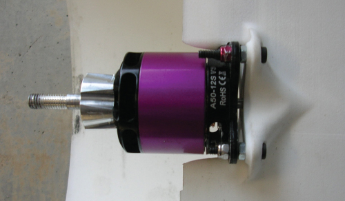
Figure 5.10 Hacker brushless electric motor.
5.3 Propellers
Perhaps the single biggest variable affecting the efficiency of the propulsion system is the choice of propeller (it is worth recalling that the Wright brothers cited good propeller design as one of the key developments that enabled them to fly their first aircraft successfully). There are very many manufacturers offering propellers in the more popular sizes, and while it might be assumed that all modern aero-modeler propellers would be essentially similar, this is far from the case. Their design philosophy, geometry, materials, and manufacturing accuracy vary considerably – all of which impact on the efficiency. Brandt and Selig [12]5 show that peak efficiencies vary for such propellers from 43% to 65% for two-bladed devices of similar diameters, even when operating at the correct advance ratio for the chosen pitch. If at all possible, it is best to use two bladed propellers since these have best efficiency, but, particularly for pusher configurations, installation difficulties may force the choice of three-, four-, or even five-bladed propellers. At large sizes and in pusher configuration, the choice of material and manufacturer becomes more limited. Where possible, we adopt APC Thin Electric propellers because of their very good efficiencies.6 See also the spreadsheet available from RC advisor.7
Of course, propeller thrust also varies very significantly with variations in advance ratio (i.e., airspeed compared to propeller speed). As the airspeed seen by the propeller changes, if the rotational speed does not, the various aerodynamic sections of the propeller see different angles of attack, and just like wings, these sections stall if the angles are too high or low. Thus a fixed-pitch propeller will have to compromise between thrust during takeoff and while at cruise speed and at maximum airspeed. On large aircraft, this difficulty is overcome by using variable-pitch propellers, but as already noted, these are not generally available for small UAVs (we have had mixed success in trying to build such devices). The freely available code JavaProp8 can be used to rapidly assess how propeller performance is likely to change with operating conditions.
To use JavaProp, one specifies at least the propeller outer and hub diameters, number of blades, rotational speed, forward velocity, and then one of torque, thrust, or power. It is also possible to insert sectional properties for the blades, but we generally leave these as Clark Y airfoils operating at a Reynold's number of 100 000. A design is then produced for the given forward velocity along with details of the performance at the input operating point. By next shifting to the “Multi Analysis” tab and selecting one of rpm, power, thrust, torque, or forward velocity, it is possible to generate tables of thrust (and other properties) for a range of conditions for the just designed propeller. Since most engines tend to be fixed-torque devices, we mostly choose that option both to design the propeller and to analyze it at other operating points (if the torque is not known for a given IC engine, this can be estimated from appropriate BMEP values; 1.0 MPa for four-stroke engines and 0.85 MPa for two-stroke engines). Figure 5.11 shows a typical set of outputs from JavaProp.
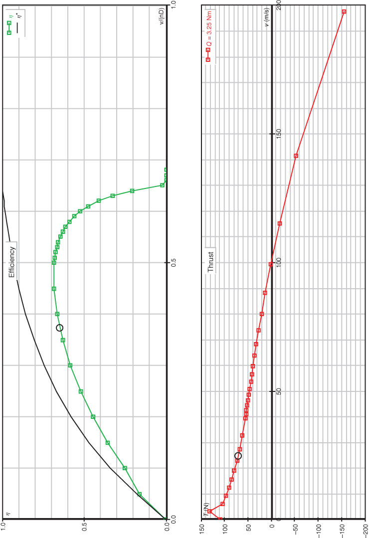
Figure 5.11 Outputs from JavaProp “multi analysis” for a propeller operating at fixed torque. Note the differing horizontal scales.
Note the design point: here a typical cruise speed of 25 m/s is shown by the small circle and is slightly below the peak efficiency for the design. Peak thrust occurs at about 4 m/s, ensuring a good ability to start the aircraft rolling on a grass field.
5.4 Engine/Motor Control
All engines or motors require some form of control. At its simplest, this is a radio-controlled servo linked to the throttle on the carburetor (preferably by a ball-jointed, backlash-free linkage). Even such a basic system requires some form of fail-safe capability that shuts the engine down if control of the aircraft is lost, allowing controlled descent glide-down to the ground. For spark ignition systems, some form of spark generation and distribution is required; for multi-cylinder engines, it is common to fire multiple plugs simultaneously even though not needed and/or combined with multiple ignition systems timed for different cylinders. For fuel-injected systems, some form of engine control unit (ECU), which monitors at least engine speed and perhaps other parameters, will be necessary, again duplicated if multiple cylinders are in use. For electric motors, a digitally controlled three-phase output speed controller is the most common solution. These can be as expensive as the motors they control, since typically they must convert high-current DC sources to high-current, variable-frequency three-phase supplies.
5.5 Fuel Systems
If a wet fuel engine is used, some form of fuel tank becomes necessary. Commonly, these are separate items with some form of closure where supply, filler, and air lines are installed (with the filler readily accessible for refueling). They are available in a range of sizes and can be obtained for methanol- or gasoline-based systems (generally not interchangeable - note also that fuel pipes must be chosen to suit the fuel in use; gasoline rapidly degrades many forms of plastic pipe), see Figure 5.12. If SLS nylon structures are being used on the aircraft as we commonly do, the fuel tank can be formed as an integral part of the structure, as already noted in Chapter 4, allowing for very large capacities with minimal tank weight. In all cases, some form of fuel pick-up must be included that allows for the aircraft to roll and pitch without leading to engine fuel starvation. This is commonly in the form of a “clunk” – a heavy-weighted end that fixes to the pipe inside the tank so that it always lies at the bottom with the remaining fuel.
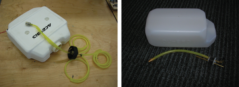
Figure 5.12 Large UAV fuel tanks. Note clunks and fuel level sensor fitting at rear left-hand corner of one tank.
The fuel tank should be sited either close to the engine (minimizing pipe runs) or near the center of lift (minimizing the impact of fuel usage on trim). The choice largely depends on the total fuel load: if only modest endurance is needed, then placing the tank close to the engine is good practice; for long-endurance aircraft where the weight of fuel may be many times that of the engine, a location near the main wing center becomes important. If a pusher propeller configuration is adopted, sometimes it is possible to achieve both aims at once. The aircraft of Figure 5.7 has a separate fuel tank placed just behind the main spar and is thus only a few centimeters forward of the engine. In the case of the SPOTTER aircraft of Figure 5.8, a large central monocoque tank is used. Since the OS GF40 engines used on this aircraft incorporate diaphragm pumps, the lengths of fuel pipe are not an issue. For engines without such systems, it may be necessary to install a dedicated fuel pump to pressurize the fuel lines, though this can lead to dangers of engine flooding at idle settings. It is important to test all such installations at a range of throttle settings and pitch and roll angles before flying, to ensure that fuel starvation or flooding is not a problem.
The final part of the fuel system is some means of checking on the amount of fuel remaining during flight. At the most basic level, the time in the air can be recorded and compared against known fuel consumption rates from earlier flights along with visual inspection of the amount of fuel on board before commencing flight. While this may suffice for short tests and smaller aircraft, it is not workable for long-endurance systems where some kind of in-flight fuel monitor is necessary. While float systems can be used for these purposes, we prefer to use optical sensors that detect low fuel levels and trigger alarms, typically at 25% and 10% remaining levels, see Figure 5.13. These sit on metal inserts glued into the nylon and are sealed with O-rings.
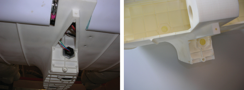
Figure 5.13 SPOTTER fuel tank level sensors. One sensor lies behind the central flap in the upper wider part of the tank (just visible in the right-hand image), while the second one lies at the bottom just above the payload interface.
5.6 Batteries and Generators
All UAVs need on-board electrical power for avionics and control; those with electric motors also need high-power supplies for propulsion. Most commonly, these needs are met by battery supplies, optionally augmented by engine-powered generators for in-flight recharging. For most purposes, we prefer the ruggedness and resilience of NiMH or LiFe batteries wherever possible. For main propulsion batteries, LiPo systems become necessary to achieve the required power densities. Great care is called for when using LiPo batteries, as they are a major fire risk if they are damaged or misused. A wide range of capacities and voltages are readily available, though the best quality high-density LiPo batteries are expensive.
With all batteries, maintenance is very important, and we keep dedicated battery use and charge logs for all flight-critical batteries. Batteries should not become discharged too far, be overcharged, or be stored in inappropriate charge states if they are to give their best. It is also important to note that batteries represent a real fire risk, and in many countries transport of battery packs can constitute a hazardous load and be subject to regulation. Ideally, charging should be carried out in dedicated environments with suitable fire control measures in place.
For long-endurance UAVs, it is important to segregate batteries to ensure that critical systems never lose power. This can also simplify wiring and reduce unwanted noise on important control lines. For example, using separate batteries for receivers/servos and ignition systems is often desirable. If a single charge of a battery will not support an entire mission, then on-board recharging becomes necessary: we use brushless motors driven directly or by toothed belts from Wet-fueled engines to provide the required power, along with suitable battery conditioning circuits to guard against overcharging, see Figure 5.14.

Figure 5.14 Engine-powered brushless generators driven directly or by toothed belt.