Chapter 12
Preliminary Geometry Design
Once the spreadsheet analysis has been completed and a set of preliminary dimensions has been found, a more realistic series of analyses can be undertaken before the project is passed on for detailed design. The purpose of these analyses is to check that a number of the key assumptions made when using spreadsheets to size the aircraft will be borne out in practice. The primary checks that need to be completed before proceeding on to detail design are typically the following:
- that the lift and drag estimates for the aircraft in cruise, turn, takeoff, and landing configurations are sufficiently accurate that the desired aircraft performance will be achieved.
- that the flight stability of the aircraft will be acceptable.
- that acceptable stress levels in the primary aircraft structure can be achieved within the allowable weight budget.
- that the aircraft can be made sufficiently stiff to avoid control surface operational and aeroelastic problems within the allowable weight budget.
The majority of the calculations underpinning these checks depend on the quality of the geometrical description available, so we begin by first building a much more realistic model of the airframe. Such models can be generated in a variety of ways but, if they are to include more than just the lifting surfaces, they almost always depend on some form of computer aided design (CAD) program. Here we continue to use the AirCONICS system1 that drives the Rhino CAD platform.2 Typical outputs from this process have already been shown in the previous chapter; here we give more details on how this works and the steps involved in producing realistic wetted surfaces for the airframe, including control surfaces and a series of components sufficient for preliminary structural analysis.
Once this definition is in place, more detailed experimental aerodynamic data and computational fluid dynamics (CFD) approaches can be used to check the lift and drag performance and stability of the airframe against the assumptions already made in the spreadsheet analysis. If necessary, the spreadsheet process can be refined in the light of such information and the geometry updated: generally any deficiencies in the aerodynamic characteristics will lead to changes in the overall planform shape. Then attention can be turned to the internal definition of the airframe structure and more refined hand calculations, backed up by finite element analysis (FEA), applied to check stressing and stiffness, including aeroelastic effects. When an adequate structural model is also in place, a relatively rigorous weight and center of gravity check can be made. Again, if the spreadsheet assumptions are inadequate, refinements can be made and the whole process updated – structural problems typically lead to increases in the estimated weights, which will adversely impact on wing loading and thus may require modifications to the planform shape. Finally, and only when all is well, the detailed design that ultimately leads to the final definitions needed for manufacture can begin. Sometimes a series of experimental models will be built and tested before final production is committed to; these can be used to validate any computations carried out as well as providing data for future design studies.
12.1 Preliminary Airframe Geometry and CAD
Because it may very well be necessary to iteratively build and analyze the airframe geometry model several times before a fully accurate and balanced design is achieved that passes the checks just noted, it is of enormous importance that the process for generating the airframe geometry is as automated and robust as possible. This is precisely the rationale behind the AirCONICS suite and why we find its use in this stage of design so important. It is, however, not the only way to produce initial CAD definitions; almost all modern CAD packages support some form of parametric geometry capability that can be programatically controlled. Essentially, this involves first deciding the basic topology of the airframe and then linking as many geometry variables as possible to each other so that only a small number need to be specified as the airframe is changed during sizing and balancing. For the examples studied here, the full geometry is typically fully defined by around 20 master dimensions, see, for example, those specified in Tables 11.9, 11.3, and 11.8.
To generate the geometry used for analysis, we first need an outer wetted surface for the aircraft. As already noted, our preferred tool is Rhino since this can be readily controlled with Python scripts and quickly produces clean and closed wetted surfaces. Since all aircraft contain a range of similar features, most noticeably airfoil-like lifting surfaces, the AirCONICS suite of Python scripts generates these very efficiently. The basic components of the airframe are then built from wing, taiplane, and fin lifting surfaces, linked together via tubular spars with a range of “pods” and cylinders created as elongated bodies of revolution to represent fuselages, junctions, and cowlings. All these elements are joined together to form a single closed “polysurface” that can be exported directly to the analysis tools used for aerodynamic and structural analysis. Simple undercarriage elements can be included by using toroidal tires and fin-like structures for the legs (although it is normal to omit these while carrying out initial CFD validations of drag). Payload pods can also be added at this stage if required. Figure 12.1 shows a typical Rhino airframe as built using AirCONICS, here for a single tractor engine, twin-boom, H-tail design. Note that a tapered wing planform has been adopted but with straight leading edge – this simplifies the structural design by allowing adequate space for a straight wing spar.
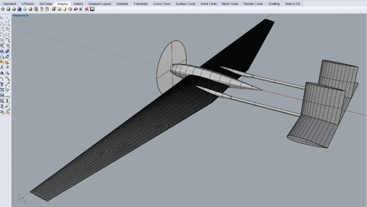
Figure 12.1 Basic AirCONICS airframe geometry for a single tractor engine, twin-boom, H-tail design.
The Python scripts used to create our geometries essentially consist of three distinct sections: first, a short section of code is used to define the variables taken from the spreadsheet as a set of controlling parameters, see, for example, Figure 11.5. Second, all the main functions are defined that will be used in the geometry creation. Typically this would include the following:
- A set of functions that vary with span to define each lifting surface (generally different for the wings, tail and fins):
-
– DihedralFunction. A user-defined function describing the variation of dihedral as a function of the leading-edge spanwise coordinate.
-
– TwistFunction. A user-defined function describing the variation of twist as a function of the leading-edge spanwise coordinate.
-
– ChordFunction. A user-defined function describing the variation of chord as a function of the leading-edge spanwise coordinate.
-
– SweepAngleFunction. A user-defined function describing the variation of sweep angle as a function of the leading-edge spanwise coordinate.
-
– AirfoilFunction. A user-defined function of the previous functions to set up the variation of cross-section as they vary with the leading edge spanwise coordinate.
-
- A small group of operators to define pods as bodies of rotation created from airfoil sections with optional parallel middle sections.
- A small group of operators to define landing gear elements created from cylinders, struts, and a torus for the tire.
Following this, the main body of the script invokes the various functions plus a few inbuilt objects, such as simple cylinders, to build all the aircraft elements and union them together into a single closed “polysurface” solid that can be exported either as an STL file to a meshing tool or as a Parasolid, ACIS, STEP, or IGES file for use with other CAD packages. We also provide options in the script to include control surfaces and to subdivide the whole airframe into parts suitable for preliminary structural analysis.
12.2 Designing Decode-1 with AirCONICS
If the dimensions for the Decode-1 design given in the previous chapter are used in this way, the Rhino geometry already shown in Figure 11.3 can be generated. Note that a circular cross-section fuselage has been adopted but with airfoil-like leading and trailing parts; parts at the rear would need to be cut away to accommodate the engine in the actual design, but at this stage it is not practical to model the full details of the engine nor would this be desirable for preliminary aerodynamic calculations. A propeller disk and hub can be modeled, however, by extending the fuselage cone down to a point and including an actuator disk model in the CFD analysis. In the actual design, the entire middle body of the aircraft between the tail booms and including their junctions with the wing are to be manufactured as a set of SLS nylon parts. It will therefore be possible in the detailed design stage to add fillets and fairings between the various items. Whether or not such items matter during preliminary design is not completely obvious – they tend to make little difference to the CFD drag predictions but they will help reduce drag in reality. However, since drag prediction using CFD is notoriously difficult, this may not be worth the effort at this stage and any drag savings are likely to be swamped by losses arising from items like the unfaired engine and various unrepresented items on the undercarriage legs and wheels, aerials, and so on.
The complete Python script for producing the Decode-1 AirCONICS model is given in Appendix B. This script enables the outer mold surface to be generated and the resulting body to be divided into its major structural parts, see Figure 12.2. This is sufficient for aerodynamic and stability analysis and the structural sizing of the main spars and booms. To carry out more precise stressing or to prepare parts for manufacture, further effort is required. Some of these steps can be fully automated with very little further designer input, as will be seen later, while other aspects will require the selection of various additional subsystems such as engines and undercarriage, servos, and spar clamping arrangements. All these aspects should ideally just require selections to be made from libraries of pre-existing parts, which are then joined together with the outer mold line definitions. Generally, the addition of such parts lies in the scope of detailed design, see Chapter 17.
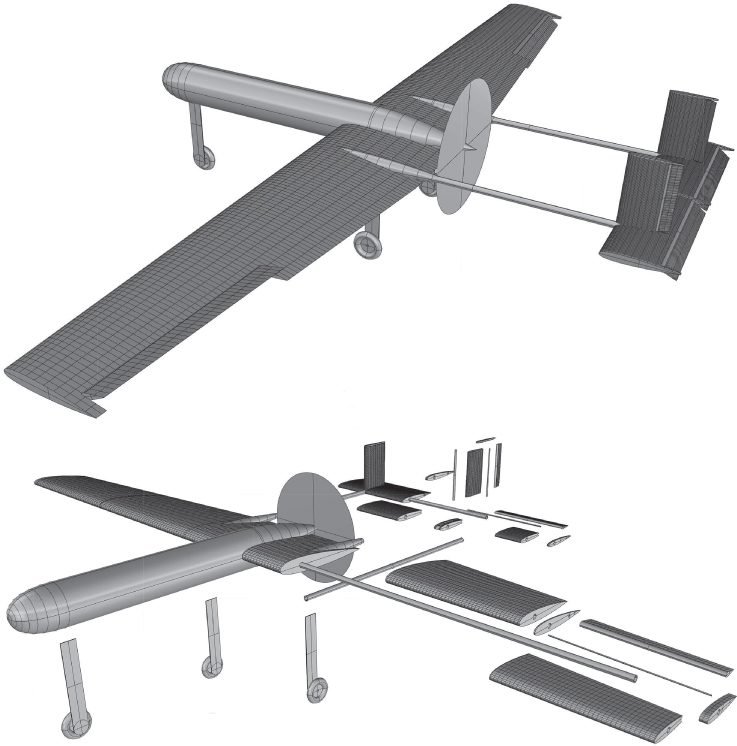
Figure 12.2 AirCONICS model of complete Decode-1 airframe with control surfaces, undercarriage, and propeller disk.