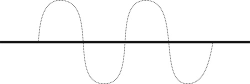
An analog signal is a sine wave. Like an ocean wave in constant motion, an analog signal continually changes over time. In fact, the term analog is actually derived from the word analogous because of the signal’s analogous relationship to the sine wave (Figure 11.1). Digital information, on the other hand, is fixed and absolute and does not change over time. When information is digitized, the data remains as it was originally recorded.
Analog Domain
In the Introduction of this book, we said that sight and hearing are responses to energy waves, which is an analog phenomenon. Video
was originally developed as part of the analog world. Because the system was analog, it had the ease and advantages of fitting into the natural physical system. However, it also carried with it all the interference and noise problems. Noise is analog information just as video and audio are. Getting rid of noise and interference in the analog video signal is not easy, as they take the same form as the video and audio signals. Also, manipulating analog information for creative purposes is complex.
To eliminate interference problems and make better creative use of video, a process of digitizing video signals was created. Digitizing refers to converting the analog information to a series of numbers. As digital information, the signals are not subject to real-world analog interference. Real-world physical problems have no effect on the television signal when it is digitized. These compelling benefits drove the move to digital signal processing. However, as humans, we experience the world as inherently analog. Therefore, all digital processing must start by converting from analog and end by going back to analog.
Digital Domain
To create digital video, a digital representation of the analog sine wave had to be created; that is, the analog sine wave had to be recreated digitally. To do this, a process was developed to measure the sine wave at different times and assign a numerical value to each measurement. A sine wave curve is constantly changing over time. Therefore, the more frequently this measurement is taken, the more accurate the digital reproduction of the sine wave will be. A doctor measuring a patient’s temperature once a day might not get a very accurate picture of the patient’s condition. However, taking a reading every hour will give the doctor a much clearer idea of the patient’s progress.
Sampling Rate
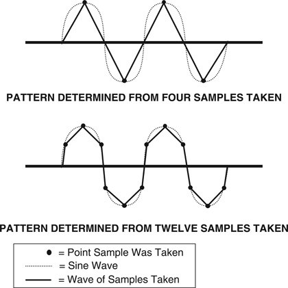
Another way to think of digitizing is to imagine a connect-the-dots puzzle. The more dots there are to connect, the more closely the curves and outlines will reproduce the picture. The frequency of the dots, or the doctor’s temperature readings, are referred to as the sampling rate. If the sine wave was measured every 90º, there would be three straight lines instead of a curve. However, if the sampling rate was increased to every 10º, 5º, or even every 1º, the curve of the sine wave would be more accurately represented (Figure 11.2).
There were two factors affecting how the sampling rate for digital video was determined. First, the sampling had to occur frequently enough to accurately reproduce the analog signal. Second, the
process had to be simple enough to integrate with the existing analog system. The one element that satisfied both factors was the use of the subcarrier frequency. The subcarrier frequency was used as the basis of the sampling rate because it was the main synchronizing signal for the analog video system.
However, using a sampling rate that equals the subcarrier frequency does not create an accurate representation of the analog information. To accurately reconstruct the analog information from the digital samples, the sampling rate must be more than twice the highest frequency contained in the analog signals, or conversely, the frequencies being sampled must be less than half the sampling frequency.
This conclusion was derived by Harry Nyquist, an engineer at Bell Laboratories (originally AT&T), who in the mid to late 1920s published papers on factors concerning telegraph transmission speed. Other scientists, Karl Küpfmüller and Vladimir Kotelnikov, had come to a similar conclusion as Nyquist. And later, around 1948, an engineer, Claude Shannon, applied Nyquist’s work to digital sampling. So while this sampling frequency rule may be known by different names, it’s predominantly called either the Nyquest Theorem or the Nyquist-Shannon Sampling Theorem. (The error that is created by working outside this criterion is called aliasing, the creation of a false signal based on incorrect data derived from ambiguous samples.)
To accurately represent the analog information in a video signal, it was decided that a multiple of the subcarrier should be used. The sampling rate decided on was four times the subcarrier frequency for the luminance signal and two times the subcarrier frequency for the color components.
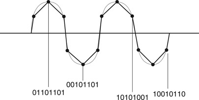
Simple mathematics of multiplying 3.58 megahertz (color sub-carrier frequency) times 4 will give a sampling rate of 14.3 megahertz. To accommodate world standards, the actual final sample rate for digital component signals is 13.5 MHz for the luminance channel and 6.75 MHz for each color channel. A value is assigned to each reading, and that number is recorded. What is recorded is not a real-world analog signal, but a series of numbers representing video and audio levels at each instant the signal was sampled.
When video signals became High Definition, higher sample rates were needed to capture the greater detail. In HD, the luminance sample rate is 74.25 MHz and the color components are sampled at half that rate or 37.125 MHz. Each new higher resolution image requires a higher sample rate. 4K systems have twice the amount of information on each line, and twice as many lines. As a result they must sample the analog world 4x faster than HD. 8K image systems must up the rate again by another 4x.
Certain numbers keep coming up when dealing with digital equipment. For example 4:2:2, 4:4:4, and 4:4:4:4. The numbers represent digital sampling standards for video signals. For example, 4:2:2 represents four times the subcarrier frequency as the sampling rate for the luminance portion of the signal, and two times the subcarrier frequency for each of the color difference signals. 4:4:4 represents four times the subcarrier frequency for all three of those signals and 4:4:4:4 adds the key signal, or alpha channel, as part of the digital information. While these numbers are mathematically accurate with Standard Definition signals, they are retained when talking about HD as well. The ratios remain, but there is no longer a direct relationship to the frequency of the subcarrier.
Computer Processing
Early computers functioned using a series of switches that were either on or off, providing either a yes or no option. This could be likened to a questionnaire created to find out someone’s name where only yes or no answers can be given, each answer represented by a 0 or 1, respectively. To give a person’s name, a letter from the alphabet would be offered and the person would say yes or no to indicate whether that letter is the next letter in his or her name. They would go through the alphabet with the person answering yes or no to each letter, then repeating the process until the full name was spelled correctly. The process would be slow but accurate.
That is essentially what a computer is doing as it goes through its memory. The faster it goes through the yes and no questions, the faster it can process the information. The rate at which this information is processed is measured in megahertz and is one of the specifications that differs from computer to computer. The higher the rate as measured in megahertz (MHz), the faster the computer processor.
Binary System
Each of the yes or no answers referred to above is represented by a zero or one, or combination of zeros and ones. This is called a binary system because it is made up of two numbers. The binary system is used for all digitizing processes because it is the language of computers. Each zero and one is a digital or binary bit. The number of binary or digital bits the computer can read at once is known as the word size. The original computer processors were 8-bit (also referred to as a byte), but soon grew to 16-bit, 32-bit, and so on. Computers continue to increase their capability of handling larger word sizes. The bigger the word size the computer can handle, the faster it can process information. The processing speed of computers continues to increase in megahertz as well. These two factors combined have been responsible for the increase in computer efficiency and speed.
Unlike the binary system, which is based on two numbers, the common mathematical system in use today is the decimal system, which uses values 0 through 9. In this system, the column on the far right represents ones, or individual units, and the next column to the left represents tens of units. The third column to the left represents hundreds of units, the fourth column represents thousands of units, and so on. Each column has a value from 0 to 9. After 9, a new column is started to the left. For example, 198 is represented as an 8 in the ones column, a 9 in the tens column, and a 1 in the hundreds column. After 198 comes 199 and then 200. A 200 means there are 2 hundreds of units, 0 tens of units, and 0 individual units.
Table 11.1
Binary System Values
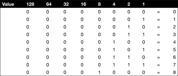
In the binary system, a computer does the same type of math but its columns only have values of 0 and 1. The first column
represents ones or individual units. The second column to the left represents twos of units. The third column represents fours of units. The fourth column to the left represents eights of units, and so on.
Using the table above, if there is a 1 in the second column and a 0 in the first column this indicates there is one unit of twos. The number 3 is represented by a 1 in the first column and a 1 in the second column, indicating 1 unit of twos plus 1 individual unit. The number 4 is a 1 in the third column and a 0 in both the first and second columns, indicating 1 unit of fours and 0 units of twos and ones. Five is represented by 1 unit of fours, 0 units of twos, and 1 individual unit, or 101. A 1 in each of the eight columns, or 11111111, represents the number 255. The number 256 is the start of the ninth column. Thus, the largest word that an 8-bit computer can process at a time is eight bits or one byte.
Sample Size
A second factor in sampling is how much information each sample can carry. If a single bit is used for sampling, that would only indicate if there is a signal present or not, but would in no way represent its analog value. If more bits are used, more accurate analog values can be represented in the sample. For example, with four bits, the analog signal could be any one of 16 different voltages. In video, 8 or 10 bits are typically used for each sample. This creates either 256 (using 8 bits) or 1024 (using 10 bits) different levels at each sample.
Human hearing is more sensitive than vision to errors in the sample size. As a result, audio sample sizes are typically 16 or 24 bits per sample.
Digital Stream
Once data has been digitized, the digital bits that comprise the data can be transmitted. The form of transmission used for digital data is referred to as serial digital. The term serial refers to the series of binary bits that are sent out as one continuous stream of digital data, or the digital stream. When working with a video signal, this digital stream contains all the information about the image and audio.
The quantity of data in a digital stream dictates the quality or detail of the image. The more detail—or sampled information—from the image, the larger the quantity of data (Figure 11.3). The larger the quantity of data, the greater the amount of bandwidth required to transmit the data. This movement of data is referred to as throughput. The larger the bandwidth—or the greater the throughput—the greater the quantity of data that can be carried in the serial digital stream. If the bandwidth used for transmission is too small for the quantity of data being carried in the digital stream, digital bits are dropped or lost. The result is a loss of image quality. In some cases, this can result in a complete loss of the signal.
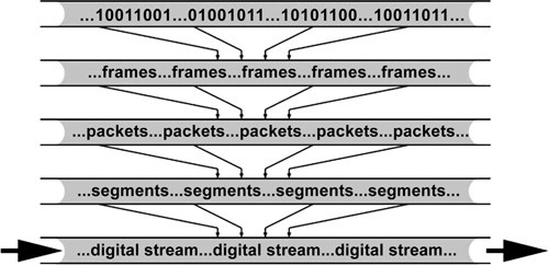
In order for the digital stream to be received and interpreted correctly, all of the digital bits must be organized. Organizing digital
data is similar to adding punctuation to a group of sentences. Without punctuation, it would be difficult or impossible to read the material and comprehend it. Digital data begins as bits, in the form of zeros and ones, which are grouped into elements called frames. Groups of frames are organized into packets. Groups of packets are organized into segments. The result of a group of segments is the digital stream (Figure 11.4).
Each of these elements in the digital stream is encoded so it can be received and combined in the proper order. If some of the information from the digital stream is lost from any one of these elements, the data, or image, can become unintelligible to the receiving source. In addition to data originating from one source, a serial digital stream may also contain information from several other sources. Just as a single computer is not the only active participant on the Internet, several sources transmitting various types of data may share a single transmission line. It is for this reason that the frame, packet, and segment information is critical. Without this data, there is no way to decode the serial digital stream to recreate the original data at the intended receiving source.
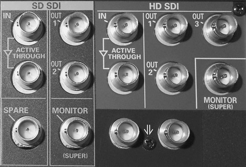
Serial Digital Interface
The transfer of data from one source to another occurs through an SDI, or serial digital interface. This interface allows the transfer of data between sources. An SDI is sometimes a stand-alone device and sometimes it is incorporated as an integral part of a piece of equipment. An SDI input/output port can be found on cameras, VCRs, and other production and computer equipment (Figure 11.5).
Along with the video information embedded in the digital stream is all the audio information—up to 16 channels. There are no separate wires for audio. All of the video and audio data is contained in a single serial digital stream and carried through a single SDI cable.
HDMI Interface
Another very common interface for carrying digital signals is HDMI. This is the most common interface on consumer cameras, displays and computers. While it is not directly compatible with SDI equipment, inexpensive transcoders allow HDMI devices to be used in a professional environment. Because HDMI signals are limited to about 20 feet, they cannot be easily used in a large studio.