The majority of codecs in use today are based on the principles developed for MPEG compression. Remember, MPEG compression was developed by the working group of authorities, Motion Picture Experts Group (MPEG) formed by the ISO and the IEC. It defines the standards for compressing moving images. In fact, MPEG compression is really a set of tools that can be combined in different ways to compress video files. New tools have been regularly added to the standard leading to an ever more efficient compression. This chapter will take an in-depth look at how an MPEG-2 compression works in order to lay a foundation for the MPEG process.
The MPEG Process
The MPEG process starts by analyzing a sequence of video frames known as the video stream. Redundant information is encoded and compressed. The compressed video stream is then encoded into a bit stream. The bit stream is then stored or transmitted at the bit rate called for by the playback equipment. The data is decoded and uncompressed when it is to be used and the image restored to its original form.
MPEG compression utilizes a combination of two different compression schemes, spatial and temporal. Spatial compression reduces the quantity of data contained in each frame of video by eliminating the redundant data within the image. Temporal compression compares the changes between the images over time and stores the data that represents only the changes.
Spatial compression uses the same technique as JPEG compression, described in the previous chapter, to create an intra picture, called an I frame. Unlike the temporal compression frames, the I frames are complete “stand-alone” images that can be decoded and displayed without reference to any surrounding frames.
The I frames are interspersed within the video stream and act as references for the temporal compression between frames. The arrangement is somewhat like a picket fence, with the I frames representing the relatively few fence posts while the temporal frames are the many pickets. The temporal compression frames, called B and P frames, contain motion information that describes how the different regions of the I frame have changed between the intervening frames. The B and P frames contain far less data than the I frames. They contain only the data about the changes that have occurred between frames. This accounts for the great efficiency of MPEG encoding. Compression rates of 25:1 can be achieved with little or no noticeable degradation in the quality of the uncompressed image. I frames and B and P frames are described in more detail below.
I Frames
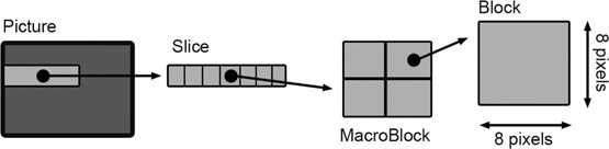
An I frame (intra picture) is one frame that is a complete image sampled in detail so it can be used as a reference for the frames around it. Each I frame is divided into 8 × 8 pixel blocks which are then placed in groups of 16 × 16 pixel blocks called macroblocks
(Figure 15.1 (Plate 20)). These macroblocks are then compressed using a variety of compression techniques. I frames are created as often as needed and particularly when there is a substantial change in the image content. In a typical video stream, this occurs approximately two times per second.
P Frames
The frames before and after the I frame, labeled P and B, contain the data representing the changes that occur between themselves and the I frame. P frames (predicted pictures) contain descriptions of how the pixel blocks in the previous frame have changed to create the current frame. In addition, the P frames are examined to see if data blocks have moved. Subject or camera movement might cause some image blocks to have the same data in each frame, but in a different location. These descriptions of distance and direction of movement are called motion vectors. The decoding process for the current frame looks backward at the previous frame and repositions the pixels based on the P frame motion vectors. The previous frame could be either an I frame or another P frame.
If there is a substantial change in the image, new pixel blocks are created for the portion of the image that has changed. These new blocks are derived from the source video and use the same encoding method as the I frame. P frames cannot stand alone or be directly accessed, since they are dependent upon the information in the previous frames from which they are derived. P frames contain much less data than I frames and are therefore simpler to encode.
B Frames
B frames (bidirectional pictures) are similar to P frames in that they are made up of motion vectors and picture blocks. The difference is that they look both forward and backward to compare pixel blocks, where the P frames only look backward to the previous frame.
When new elements enter the picture, the pixels in a B frame can be compared forward or backward to pixel blocks in either I or P frames. The data representing the difference between the previous and following frames is used to create the B frame.
Using B frames causes delays in the transmission of the bit stream. As the encoder must wait to see what is contained in future frames, the data is buffered until that data is available. Transmission of the data cannot occur until the B frames are able to be calculated. Because of this potential delay in playback, B frames are not used in all forms of MPEG.
The B and P frames both consist of data that reflects only the changes between the frames and not data about the complete image itself. For this reason, neither B nor P frames can stand alone as single images.
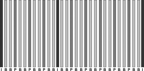
The Group of Pictures (GOP)
I, B, and P frames are grouped together to form a Group of Pictures, or GOP. A GOP must start and end with an I frame to permit its use as a reference for the surrounding B and P frames. A GOP can contain just P frames or both B and P frames in between the I frames. The number of B frames or P frames within a GOP can be increased
or decreased depending on image content or the application for which the compressed video is intended. For example, a fast-moving action sequence with complex content (lots of detail) would use shorter groups, hence more I frames. Group lengths typically range from 8 to 24 frames. Figure 15.2 shows the typical GOP structure for 30 frames of IBP-encoded video stream.
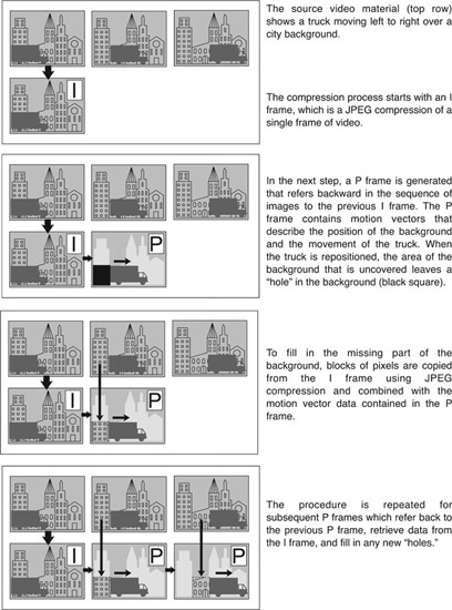
IP Method
Excellent compression quality can be achieved using just I and P frames, even though the P frames only use backward references in time. The following example shows three frames of the source video material encoded only with I and P frames (Figure 15.3).
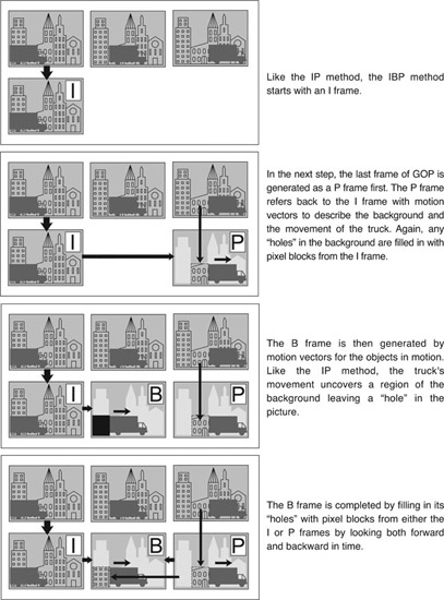
IBP Method
The addition of the optional B frame increases the compression quality but lowers the rate of data transmission. The B frame looks both forward and backward in time so the frame with the most helpful information can be used as a reference (Figure 15.4).
Profiles and Levels
The I, B, and P tools can be combined into progressively more sophisticated compression techniques called profiles. Picture quality can improve depending on the profile used. Each profile can be divided into levels of quality, depending on the compression tools used and the physical parameters of the compressed video, such as the picture size, resolution, and bit rates. There are four levels that provide a range of picture quality, from limited definition (¼ resolution video) to high definition with 1080 scan lines. Each level has its own specific standard for the input video, such as Standard Definition video or High Definition video.
Main Profile at Main Level
The different profiles and levels can be mixed and matched to create a wide variety of picture sizes, bit rates, and encoding qualities. The most useful combination for Standard Definition images is the Main Profile at Main Level (abbreviated as MP@ML). Main Profile means that I, B, and P frames can be used for compression, and Main Level means that the picture resolution is 720 × 480 in NTSC. Different storage, delivery and transmission systems have different bit rate constraints. The I, B, P compression tools are flexible enough that MP@ML can adjust the bit rates. Lowering the bit rate reduces the picture quality unless it is compensated for by using more sophisticated encoding tools.
High Definition Profiles and Levels
MPEG-2 has a number of Profile and Level combinations designed for High Definition images as well. Main Profile at High Level is for the two HD formats, 1920 × 1080 and 1280 × 720. ATSC
and DVB broadcast formats use MP@HL, however the chroma is heavily subsampled to 4:2:0, which represents the lowest digital color sampling (color subsampling is discussed in the following section).
Table 15.1
Samples of Various Bit Rates for Main Profile at Main Leve
|
Bit rate
|
Application
|
| 1.5 Mbits/sec |
YouTube 480p (using H.264) |
| 2.5 Mbits/sec |
YouTube 720p (using H.264) |
| 4.5 Mbits/sec |
YouTube 1080p (using H.264) |
| 3.5 Mbits/sec |
NTSC/PAL broadcast quality |
| 10 Mbits/sec |
DVD disk (using MPEG compression) |
| 15 Mbits/sec |
Equivalent to DV tape quality |
| 8–15 Mbits/sec |
HDTV quality (MPEG-4 AVC compression) |
| 19 Mbits/sec |
HDV 720p (using MPEG-2 compression) |
| 24 Mbits/sec |
AVCHD (using MPEG-4 AVC Compression) |
| 40 Mbits/sec |
1080 Blu-ray DVD |
The least compressed of the MPEG-2 Profiles and Levels is 422 Profile at High Level. This allows for 4:2:2 sampling of images up to 1920 × 1080. Data rates of up to 300 megabits per second are allowed. Several camera and recorder manufacturers use this format. For example, Sony XDCAM @ 50 megabits per second is 422P@HL.
As of the writing of this book, the MPEG-2 standard does not allow frame sizes greater than 1920 x 1080 or frame rates above 60 frames pre second. For 4K and UHD applications, other compression formats must be used. The more recent compression standard, MPEG-4, allows for larger frame sizes. Even the recent development of HEVC (or H.265) makes it the likely successor to MPEG for larger frames.
Color Subsampling
Another aspect of the compression process is color subsampling. As mentioned above, 4:2:0 and 4:2:2 are numbers that represent digital sampling standards. First, the RGB channels are converted into luminance (Y) and two chrominance channels (Cr and Cb). After converting RGB video signals into luminance and chrominance data, the chrominance portion can be compressed with little apparent loss in image quality.
NOTE As mentioned throughout the book, the human eye notices changes to luminance levels, the brightness and contrast of an image, more easily than it does changes to color. This is why reducing the frequency of color sampling can be an effective method of compression.
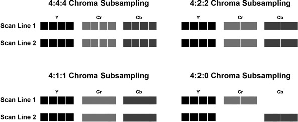
Let’s consider four different digitizing schemes for video: 4:4:4, 4:2:2, 4:1:1 and 4:2:0. In each case, for every set of four pixels on a scan line, there are four digital samples of the luminance channel. The schemes differ, however, in the amount of times the chroma in each line is sampled. In the 4:2:2 scheme, for example, only two samples are taken for each of the two chrominance channels (Figure 15.5 (Plate 21)). Each chrominance sample is shared by two pixels. As a result, the two chrominance channels are digitized at half the resolution of the luminance channel, reducing the amount of data for those two channels by 50%. This reduces the total data required for each frame of video by 33%.
4:2:0 sampling takes the idea of sub-sampling the chrominance channels a step further than 4:2:2. If, for every four pixels, there were four samples of luminance but no samples of chrominance, that would be 4:0:0 sampling. Of course, with no chrominance data you would only have a black and white picture. However, if
every other scan line was digitized at 4:2:2 and the lines in-between were digitized at 4:0:0, the chrominance data from the 4:2:2 scan lines could be shared by the alternating 4:0:0 scan lines, further reducing the amount of data required to describe a frame of video.
Figure 15.5 illustrates how 4:2:0 sampling alternates between 4:2:2 and 4:0:0 sampling on each scan line. Each chrominance sample is therefore shared by two pixels horizontally as well as two scan lines vertically. This means that the chrominance samples cover a 2 ´ 2 area, or four pixels. As a result, the two chrominance channels each have only 25% of the data that the luminance channel has. Reducing the data requirements for two channels to 25% reduces the total data required for each frame of video by 50%. 4:4:4 represents four times the subcarrier frequency for all three of the signals and 4:4:4:4 adds the key signal, or alpha channel, as part of the digital information.
NOTE While these numbers are mathematically accurate with Standard Definition signals, there is no longer a direct relationship to the frequency of the subcarrier in High Definition. Yet the ratios remain when talking about HD as well.
Alpha Channel
The process of combining or compositing images often requires a channel of transparency information to be part of the image data file. In computer graphics terms, this data is often called the Alpha Channel. It is a luminance only channel that is part of some video codecs. In areas where the channel is completely white, the image that contains the alpha channel is opaque. If part of the alpha channel is completely black, the companion image is completely transparent. Shades of gray between the two extremes are a proportional mix of the attached image and the other images in the composite.
In the world of video, this process is often referred to as keying. The key signal, or alpha channel, can be derived by the color in one of the images to be combined (often called a chroma key or green screen). The key may also use the luminance of one of the images as the alpha. Some devices, notably graphics machines, will provide a separate key signal output.
MPEG Variations
Over time, MPEG variations, such as MPEG-1, MPEG-2, MPEG-4, were developed with different compression schemes. For example, MPEG-2 compression can use a variety of computer algorithms, or mathematical formulas, to compress the images. These different algorithms can be used in combination to provide progressively increased compression without loss of quality. Different MPEG compression techniques or variations lend themselves better to specific applications.
MPEG-1
MPEG-1 comprises the Video CD (VCD) format, the quality of which is analogous to that of the output of a VHS tape. The VCD format was a popular way of recording video onto CDs before the ready availability of DVD recording. This format uses small pictures sizes, about a quarter of the size of a standard definition frame, and low frame rates to keep the data stream small enough to play back from a CD. MPEG-1 does not support broadcast-quality video and is no longer frequently used. However, as nearly every computer made since the early 1990s can play this format, it is not quite dead yet. Additionally the popular audio format, MP3, is formally called MPEG-1 Audio Layer 3.
MPEG-2
Nearly all digital video broadcast uses the MPEG-2 video compression standard, which is also used to encode audio and video for broadcast satellite and cable TV. MPEG-2 is more complex than its predecessor, MPEG-1, but it is essentially an improved version of MPEG-1. The MPEG-2 standard has a number of parts describing coding and testing of audio and video files, data broadcasting, downloading of files, and interfaces for decoding the files. MPEG-2 Part 1 defines a transport stream for the broadcast of audio and video files and a program stream for storage on media such as DVDs.
One major difference between MPEG-1 and MPEG-2 is that MPEG-2 is designed to support interlaced video as used in broadcasting while MPEG-1 does not. MPEG-2, however, also supports progressive scan video streams.
MPEG-2 organizes pixels into macroblocks (16 × 16 instead of 8 × 8). The macroblocks are processed as four blocks of 8 × 8 blocks. MPEG-2 has a definition for fields within frames. There are two fields in each interlaced frame. The field containing the odd lines is sometimes called the upper field and the lower field contains the even lines. MPEG-2 uses two types of DCT coding, frame DCT and field DCT. Frame DCT-coded macroblocks are coded from four blocks coming from the same frame of video. Field DCT-coded macroblocks can either be coded with four blocks coming from one field of video or two blocks coming from one field and two blocks coming from another field. Non-interlaced video is coded using frame DCT while interlaced video can be coded using frame DCT or field DCT. Field DCT can only be used with interlaced video.
While other versions of MPEG are more efficient than MPEG-2, there are uncountable set top boxes, TV receivers, DVD Players and computer devices that can decode MPEG-2 streams. As a result it still finds wide use in the industry.
MPEG-4
MPEG-4 is a set of coding standards designed to compress digital audio and video data. It includes many of the features of MPEG-1 and MPEG-2, but adds to them and offers increased resistance to errors and greater compression efficiency. Whereas MPEG-2 is DVD quality video, MPEG-4 delivers the same quality but at lower data rates and in smaller files. This makes MPEG-4 the best choice for streaming video on the Internet (the process of streaming video is discussed in more detail in Chapter 21). MPEG-4 is also used for distributing media over broadcast TV and to handheld media devices, such as cell phones, tablets, and so on, so its flexibility and resistance to errors introduced by transmission are key.
MPEG-4 Compression Process
MPEG-4 is processed in a visual hierarchy rather than as a series of images. Every object is represented by a video object plane (VOP) that consists of a sampling of the object over a number of frames. A group of video object planes (GOV) is similar to the GOP organization used in MPEG-1 and MPEG-2. A video object layer (VOL) is the next level of organization and consists of a series of VOPs or GOVs. The video object (VO) is all of the VOLs associated with an object.
The VOP may be thought of as an MPEG-1 or MPEG-2 video frame and is coded in a similar fashion, with I-VOPs, B-VOPs, and P-VOPs. As MPEG-2 introduced variations on the IBP system of MPEG-1, MPEG-4 has its own new techniques to improve the efficiency of compression.
MPEG-4 also uses sprites. A sprite is a video object that is static and persistent. Once the sprite has been transmitted, only perceptual variations need be updated. Sprites, being static objects, are treated and encoded much like a JPEG image.
Webcasts on the Internet are broadcast in MPEG-4, MPEG-4/AVC (Advanced Video Coding), Real Video, WMV (Windows Media Video), QuickTime, RealMedia, and 3 GP (3rd Generation Partnership—cell phone application), all of which include some aspects of MPEG-4 parts (or standards) and profiles. Each part contains a number of profiles. Most of the features are left up to developers as to whether or not to implement them so there are levels and profiles in MPEG-4 implementation, but probably no implementation that includes them all.