Traditionally television required connecting individual purpose-built devices together to build systems for creating and broadcasting content. Cameras connected to video switchers, which connected to recorders. For sound, microphones connected to mixers, which connected to the recorder as well. A show was recorded to removable media, mostly tape, and stored on a shelf. Perhaps later that tape was put on a machine that was connected to a transmitter to send the program home to its audience.
Now, of course, computer-based technology is at the center of everything media professionals do. From the biggest television networks to a single creative soul working alone, video and audio are now handled as computer files.
Large-Scale Workflows
It might be relatively easy to imagine the workflow of that creative soul working alone. That creative soul might even be you. But in order to fully understand some of the needs and possibilities of a large-scale workflow, it might be helpful to think of an imaginary
television network. The diagram in Figure 18.1 shows a generic example of a large-scale workflow that can be used to examine each of the elements and see how they relate.
Central Storage
In the middle of the workflow is the place that the files are actually stored. In the diagram, this is called Central Storage. In reality, large enterprises seldom have a single repository for their material. More likely, there is a geographically diverse group of storage clusters that contain duplicates of the material. This serves to make the media files available to people in different regions. More importantly, it provides multiple locations in case a disaster takes one of the sites offline. A broadcaster doing a large international production like the World Cup might have a storage cluster in the host country, and mirror the content to another cluster at their home base. Content creators in both countries can access local copies of the material they need. If a system failure occurred in one location, the content would still be in tact at the other.
Archive
Central Storage is used for files that are needed either in a timely fashion or on a frequent basis. The archive, however, is where files that are not currently being used, but must be saved, are located. Most often this consists of an automated tape library. When done on a large scale, this is a robotically maintained set of tapes that can be loaded and unloaded from players mechanically. Tape is both less expensive and more robust than spinning disk drives when storing large data sets. The drawback is that it cannot be accessed instantly. The tape with the requested file must be located and loaded into a player and then the file has to be copied to central storage for access.
Ingest and Quality Control
The job of actually getting material into the Central Storage system falls to Ingest operators. Feeds may come from local studios or cameras, remote feeds via microwave, satellite or fiber optic lines, or even as files uploaded by content contributors at bureaus or in the field. The Ingest operators are responsible for managing the material as it is moved into Central Storage.
Once the material has been ingested into storage, some programs and materials must be examined for quality during a Quality Control process, sometimes referred to simply as QC. This can be done in two ways. One way is to pass the material through an automated Quality Control system. The other way is to have a Quality Control operator perform a manual inspection. However it’s done, it is important that both technical standards and content standards of program material must be maintained.
Post Production
Some shows are broadcast live, such as newscasts or live sports events. But typically, a show needs to go through the post production process, where content can be manipulated and processed to prepare the show for its audience. (Post production is a huge topic outside the scope of this book.) Much of the content used by TV stations and networks is created outside the network system and brought in after it has been edited as a finished work. However, some materials may still need to be edited in association with in-house shows. Depending on the network, the post department may be modest or enormous. Something like a movie channel might have only a few seats of post production used for promotional spots or fixes, while a news or sports network might have several floors of edit rooms preparing stories, highlights, promos and other show materials.
Regardless of number, the post production editing bays all interface to Central Storage as both a source of material to work with and a place to return finished clips.
Playout and Delivery
Television networks and even local stations are not single channels. Some cable network facilities support many channels of content being made available to their audiences simultaneously. In addition, each of the channels may have multiple feeds to different time zones. Those delayed feeds might have different commercial breaks with spots tailored to regional audiences. Folks on the West Coast may be seeing a mayonnaise commercial for Best Foods brands, while the East Coast is enjoying the same spot but for Hellmann’s, which is a regional name.
Managing these details is the Playout function. Automated schedules of programs and commercials are prepared for each channel, which cue and play the material to the correct path. Playout Departments often consist of control rooms with operators using specialized equipment. Devices such as Video Servers, automation systems and scheduling software are integrated with video switchers, audio mixers and routers (Figure 18.2 (Plate 24)). For a traditional broadcast operation, this is where the product of all the efforts put into producing the content is finally delivered to the viewer. In a commercial station this is also where the advertising, which is how the bills get paid, is inserted.
Another way to access the Central Storage is Video on Demand (VOD). Many content channels make some of their material available to the audience as individual play outs by request. The topic of Video on Demand and Streaming Media is discussed further in Chapter 21.
Review and Screening
Throughout our made-up network, there are many people who will need to screen and review program and commercial content at different times during the production and post production process. For example, a producer may need to sign off on a news story before it airs. But it’s not necessary for the producer to see the story in its
highest quality form. A sports writer may need to view an edited piece that used his script, but he or she is on location using a laptop. To that end there is often a link to Central Storage from the office computer network to allow people to simply view or screen files at their desks or remotely.
Transcoding
Media files come in many different forms. These have attributes that make them ideal for one purpose, but difficult to use for another. The transcoding function makes duplicates of the material in different codecs and containers that allow each area of the facility to function based on its own requirements.
For example, the high quality files used for playout are far too large to travel through an office network for review. The transcoding function could be used to make a smaller, or proxy, copy for review purposes. And shows that will air via the Internet would also need to be a different format than the original high quality file it originated in. (In the next chapter, you will take a closer look at transcoding, codecs, wrappers and the types of files that move through this workflow.)
Media Asset Management
In a large facility, the number of files stored and accessed can quickly become overwhelming. It is the job of Asset Management to help organize the media. Asset Management is a class of programs that catalog the stored material. The catalog function allows users to sort and search the database of clips for specific material. This works much like doing a YouTube search to filter down tens of millions of clips to find the one you’re looking for.
As discussed in the previous chapter, the information about the files, or metadata, may come in part from the file itself. Workers, sometimes called Media Managers, may enter or log additional detail manually about the media assets. Later searches for material are greatly enhanced by rich detail in the metadata.
Asset management may also help process and direct the files. For example, based on a set of rules for the frequency and date of access, the program might automatically hand a file off to the archive for storage. It might also be responsible for automating the transcoding process, again based on a set of rules about what files must be available in what formats.
Computer Networking and Storage
In order to share media files among the computers used in a video operation, they must be capable of being transferred over computer networks. You’ve learned the components of a large-scale workflow. Let’s go under the hood of this operation and learn how the computers communicate in order to make this workflow possible and also how the material is stored.
Communicating Via Internet Protocol
Let’s consider an example of a simple network that has six computers connected to each other through a hub. Each computer in any network must have a unique address. Most are familiar with the Internet Protocol format, or IP address. An IP version in current use is IPv4 (Internet Protocol version 4), which uses a 32-bit number: four sets of numbers, one to three numbers in a set, each set separated by a period. One example of an IP address might be 192.16.213.254.
NOTE The total number of IP addresses that can be created using a 32-bit configuration is about 4 billion. To create more IP addresses and support the ever-growing number of Internet users and devices, a newer IP version was recently developed—IPv6. An IPv6 address uses a 128- bit number: eight sets of numbers, one to four numbers per set, with each set separated by a colon. An example of an IPv6 number would be: 2001:DB8:0:567:B3FF:0202:34:1. The various IPv6 number combinations can create many trillions of addresses.
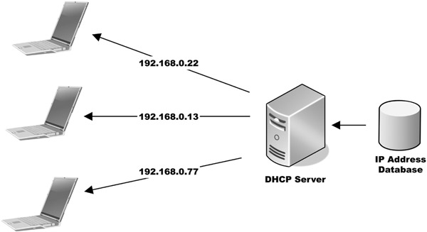
An IP address can be set by users or system administrators. In some system designs, each computer is given a fixed address so other systems know immediately where to send data. More frequently, however, a router or server—that the computer is connected to—assigns the IP address for a certain amount of time. This technique is known as Dynamic Host Configuration Protocol, or DHCP, and is most likely how your home system is set up (Figure 18.3).
The DHCP Lease
In the DHCP process, the length of time one IP address is used before assigning a different IP address is known as the lease period. The actual lease time is variable, whether it’s 24 hours or five days, and is specified on the server. A big advantage of using a DHCP server is that it renews a lease automatically, which reduces the need for a user or administrator to do it manually.
When computer number one in our example wants to send a file to computer number three, it first breaks the content into small bundles called packets. Each packet that makes up the file gets an identification number so that the receiving computer knows where it fits in the final file. The packets also get the IP address of the destination computer, number three in our case, as well as the return address of the sending computer.
The sending computer takes the first packet and sends it toward the hub. The hub then sends it out to all other computers. Each looks at the address of the packet, and ignores the data if not the intended recipient. The computer that is the intended target, in this case number three, stores the packet in the computer’s memory and sends a receipt as a message back to the sender, number one. The sender then sends the next packet in from the file.
All this works well until two computers want to send a packet at the same time. If one computer is currently sending a packet and a second computer starts to transmit, the packets collide. This corrupts the data and the transmission fails. Both computers wait a random amount of time and send their packets again.
This design was built for non-real time transfer. However in our world of audio and video, a busy network with many collisions means that the receiving computer may well run out of material to play before the next packet arrives.
In this simple example, a hub was the center of our network. Hubs are an older technology, largely replaced by devices called switches and routers. These more advanced devices do not send the packets to all the other computers at the same time. Rather they have the intelligence to examine the packets and only send them to the destination computer. Additionally some of the more sophisticated of these devices will buffer incoming packets and send them out when the lines are available—greatly reducing the collisions.
Global Networking
So far our model is of a handful of computers located close to each other. This is referred to as a Local Area Network, or LAN. However, real world networks—such as the Internet and large-scale private networks like those operated by corporations—are global and connect many millions of computers. In this Wide Area Network (or WAN) environment, two computers that want to exchange files may not be connected to the same switch or router (Figure 18.4). They may not even be on the same continent.
Often packets of data are passed from router to router through many hops as they make their way from one computer to another. With large files such as audio and video over the course of the transmission, some packets may take different routes as traffic on the network changes. When this happens, packets may arrive out of order. Most file players will buffer a number of packets before a file begins to play to help deal with this problem.
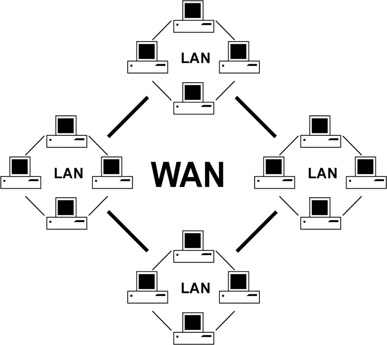
Figure 18.4
Local Area Networks Connected to a Wide Area Network
NOTE Everyone is familiar with what happens when the buffer empties before the next packet is available. A frozen picture with a rebuffering message is a frequent reminder of the difficulty of using packet networks for media streams.
In addition to traffic considerations, our networks have to be fast enough to move the amount of data contained in audio and video files. Documents do not contain really huge amounts of data. This book is less than 100 megabytes. A typical office network could move that amount of data in about eight seconds. That is great but a high quality media file compressed to that same 100 megabyte size is only about three seconds long. That means you cannot watch that file in real time on the network without it stalling repeatedly.
The office network described here moves data at a rate of 100 megabits per second. That is an older and common standard in typical office conditions. For media applications, it is far more common to connect computers at a standard that is 10 times faster, 1,000 megabits per second, or GigE as it is called. GigE speeds are easy to achieve in a LAN-type of facility where all the computers can be connected to local switches and routers. To achieve that kind of speed in a Wide Area Network (or WAN) over long distances, special provisions must be made with network bandwidth providers at a much higher cost than a typical home or small office connection.
The next big leap in speed is to something called 10GigE. This is ten times faster than the GigE connection. This is most frequently carried on fiber optic cable, as it is difficult to move signal over normal copper wire that quickly. These types of connections are usually made between switches and routers that carry traffic around a facility. It is possible, however, to give these superfast connections to computers that need more data speed than that offered by GigE connections. A workstation that is working with large RAW type data files may need this level of connection to get to the data it is manipulating at full speed.
It is also possible to lease connections of this speed from public bandwidth providers. When broadcasters are doing large remote events like the Super Bowl or Final Four college basketball coverage, they may lease these superfast connections. Not only the program feed of the game, but also individual clips on reply servers and edit systems can then be shared between studio and event.
Data Storage
In Chapter 20 you will learn the mechanics of how data is recorded onto hard drives and disk drives, and some considerations for how to group drives together to create storage clusters. Before you take that deep dive into how media is recorded onto drives, let’s take a broader look at the different storage devices and the ways they can connect to computers.
Direct Attached Storage
Direct attached storage is the class of devices that are connected directly to the computer that is responsible for storing files. Some forms of this are internal to the computer itself, either as a spinning hard disk or a Solid-State Storage Device (SSD). Others, such as a USB (Universal Serial Bus) or Thunderbolt hard drive, are mounted in external cases and connect to the computer through a cable.
While internal drives can easily record and play back media files, they are somewhat limited in capacity, based on the small number of them that fit in a computer case. There are several different ways these may be interfaced to the computer. Current common forms are SATA (Serial Advanced Technology Attachment) and SAS (Serial Attached SCSI). These technologies both build on older standards, PATA and SCSI, but work faster and with less complex wiring schemes. Both of these interfaces can move data at high speed, currently about 6 gigabits per second. That is enough bandwidth to handle even uncompressed high definition video files.
However, disk drives are mechanical devices using high speed spinning components, and frequently fail. And at these high bit rates, the interface to get the data to and from a hard drive can exceed the rate that the drive itself can read and write the data. By grouping drives together, data can be duplicated on more than one disk. This type of redundancy is referred to as a RAID system, a Redundant Array of Independent Disks. One of the advantages of RAID systems (which are discussed in more detail in Chapter 20) is that by ganging disks together and spreading the data across the drives, performance can be greater than any individual drive.
NOTE Factors influencing drive speed include how fast the disk spins and how quickly the head can be moved over the part of the disk where the data of interest is located. This is called seek time.
External Drive Connectors
Externally, individual or large groups of drives may be connected to a single computer or workstation. The most familiar here may be single drives connected via a USB connector (Figure 18.5). The USB interface has seen three major speed configurations since its development in the mid 1990’s. The first standard USB 1.0 was limited to about 12 megabits per second, which was only useful for compressed standard definition file transfer. The more common USB 2.0 was capable of 480 megabits per second and is still useful today for media applications. The most recent implementation, USB 3.0, has a very respectable data rate of 4 gigabits per second, approaching the speed of internal hard drives.
NOTE In 1994, a group of seven companies began developing USB: Compaq, DEC, IBM, Intel, Microsoft, NEC, and Nortel. Their efforts have provided a universal and faster approach for not only connecting external drives to computers, but a multitude of devices as well.
A second common method for attaching external drives is eSATA. This is the same electrical connection used for internal drives, the only difference being the shape of the connector. This gives external drives and drive arrays the ability to transfer data as if they were inside the host computer.
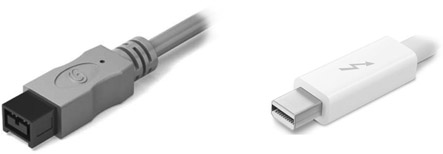
Other connection methods you may be familiar with are FireWire and Thunderbolt. FireWire is an older connection method whose speed is comparable to USB 2.0. This format was developed by Apple, and has been replaced on newer computers by Thunderbolt (Figure 18.6). A Thunderbolt connection is very fast—up to 20 gigabits per second.
Storage Area Networks
One of the principal prerequisites for file-based workflows is that files need to be shared by multiple users. While it is possible to share files from direct attached systems, it is more efficient when
the sharing is done by technologies built for that purpose. One method of doing this is via a SAN, or Storage Area Network.
One of the chief principles of a SAN is that it is a separate network designed around file storage. Unlike the common Ethernet network that is also attached to most systems, the SAN has only one job—to deal with storage access. In addition to the hardware, a management program run on a separate computer or one of the client computers manages the files.
Shared storage systems face a problem when multiple users are accessing files. While everyone can read a file without issue, if more than one computer tries to write to a file at the same time, that file will be corrupted. It is the job of the SAN manager software to arbitrate who has permission to write to the file. This function, known as locking, can happen in a few different ways. The first, volume locking, says that the first person to connect to a drive volume can both read and write the files it contains. All other users may only read the files.
Moving down to a lower level, SAN systems may use folder locking, such that only the first user in a given folder has write permission, but other folders on that volume are available to be written by other users.
Volumes and Folders
In computer systems, a volume is a large unit of storage, frequently an entire disk drive. The concept of volume is however a virtual one. A single volume can also be several disk drives working together as one. Equally a single disk drive may be subdivided into several volumes.
A folder is a virtual collection of files. Often they are seen in computer operating systems as a picture of a classic file folder. Folders may contain files and other folders.
Finally, each file may be individually locked so that only one user may write to them. Each step into the hierarchy is more computationally intense as the number of things to be protected, such as volumes, folders or files, increases.
While SANs are very efficient, they require that each client computer has a specialized interface for the connection to the SAN. Each client must also run a piece of software to allow access to the SAN, and special cabling to each computer from the SAN must be installed. This makes SANs somewhat expensive and difficult to install and maintain, typically limiting their use to large organizations.
Network Attached Storage
Network attached storage devices are typically small appliances that combine one or more hard drives with a small server computer in a single box. Once plugged into a computer network, they provide external storage that is accessible to members of that network. While these appliances are a convenient way to share files, they typically are not robust enough to provide the access speeds needed for real-time playback and recording of high data rate media.
Servers
Centralized groups of hard drives, or storage systems, can be used to provide data for a variety of users simultaneously. These storage systems are called servers. Servers come in many forms, from simple twin hard drive units to complex groups containing hundreds of disks, and they have a variety of uses. For example, once news footage is loaded onto a server, access to that footage would be available to reporters and editors worldwide the instant it was recorded on the servers’ disks. The data can be copied, changed, and stored separately by multiple users without affecting the original data, thereby providing speed and flexibility to the users. Servers are connected to client computers, or users, by standard Ethernet networks.
Network File Servers
On a much larger scale are the file servers and data storage systems that provide the infrastructure of global data communications. It is quite possible to move and share media content over the Internet with services such as YouTube and Netflix. While this public network is fantastic for final delivery to the viewer, it is generally not robust enough for media production and management. (For more information on streaming media, see Chapter 21.)
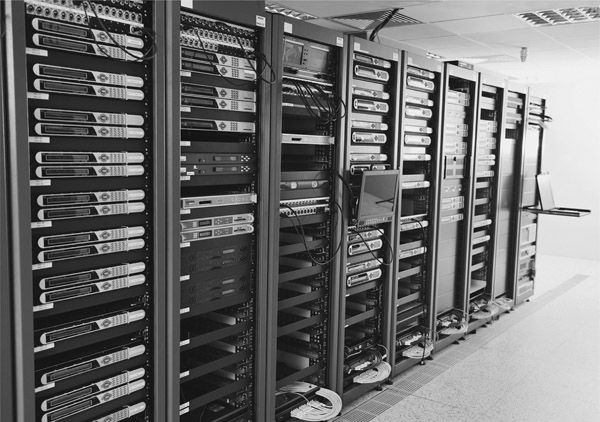
Enterprise-scale media organizations, such as TV networks or cable companies, will often build their own data networks with leased connectivity between locations and careful internal design at their facilities (Figure 18.7). These networks are separate from the public Internet and devoted to data traffic only from their owners. When properly implemented, these networks can provide the necessary storage and bandwidth for all but the most demanding of media applications.
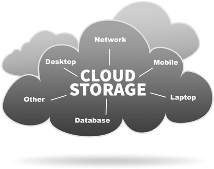
The Cloud
The author Arthur C. Clark said, “Any sufficiently advanced technology is indistinguishable from magic.” The cloud seems to be just that. With services like Google Drive, Dropbox and many others, files may be shared among users who will have no idea where or how they are stored. Of course they reside on disk clusters in data centers somewhere near cheap power and plentiful bandwidth (Figure 18.8). While public networks do not yet provide the data speeds
to make these useful for real time media operations at higher qualities, that day may come soon. Perhaps it happened from the time this book was written until you picked it up.
Storing content in the cloud has some appeals and some drawbacks. The content owner may never have to consider maintenance, upgrades or backups of cloud-based assets. All that is part of the lease costs for the space that you rent.
On the other hand, data security is harder to guarantee as the assets are on the public network. And for many large organizations, those who have business models based on charging viewers for content, this is a major stumbling block. Cloud services, because they are normally geographically distant from the user, also require expensive high bandwidth connections if they must provide real time media access.
Summary
The workflow of audio and video has undergone a huge change since the turn of the century. File-based storage and management has replaced the videotape-based workflows that dominated the industry for more than half a century. Having content available as files has been driven by, and facilitated, the growth of distribution channels. Initially only available as a broadcast to be viewed in a living room, TV can now be consumed on a variety of different objects from phones, to tablets, to screens that are wrapped around the outside of buildings.