Video starts with a camera, as does all picture taking. In still and motion-picture film photography, there is a mechanical system that controls the amount of light falling on a strip of film. Light is then converted into a pattern of varying chemical densities on the film. In digital photography, the light from an object goes through a lens, as it does in film photography. On the other side of the video camera lens, however, light is converted to an image by an electronic process as opposed to a mechanical or chemical process. The medium for this conversion has changed over the years. It began with tube cameras and has progressed to completely electronic components.
Tube Cameras
While the tube pickup has been replaced with digital technologies, the process of scanning the image that the tube used has implications for current systems.
In a video tube camera, the lens focuses the image on the face of a pickup tube inside the camera. The face of the pickup tube is known as the target (Figure 2.1). The target is light-sensitive, like a
piece of film. When light shines on the face of the target, it conducts electricity in proportion to the amount of light that is striking its surface. Without light on the face of the target, the target resists the flow of electricity.
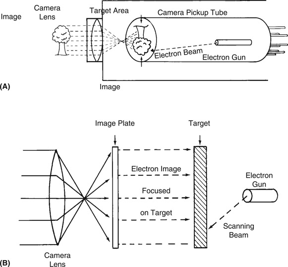
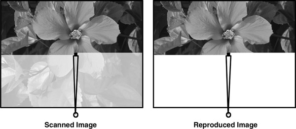
Figure 2.1 (A) Camera Focusing on Image and (B) Tube Camera Target Area
A stream of electrons, called the beam, comes from the back end of the tube and scans back and forth across the face of the target on the inside of the pickup tube. The electrical current generated is either allowed to pass from the target to the camera output or not, depending on the amount of resistance at the face of the target.
The amount of resistance varies depending on how much light is shining on the target. The electrical signal that flows from the target is, in effect, the electronic re-creation of the light coming from the scene at which the camera is aimed.
Scanning the Image
When a camera sees an object, it begins scanning the image. The beam of electrons sweeps back and forth across the inside face of the target. Where the electron beam strikes the face of the target, it illuminates an area the same size as the electron beam (Figure 2.2). The resulting electrical signal is a continuous flow of varying voltages representing the light that struck the target. Without some information about where the scanning dot was positioned there would be no way for the receiver to know where to start and end the picture. In a later chapter we will see how that is accomplished.
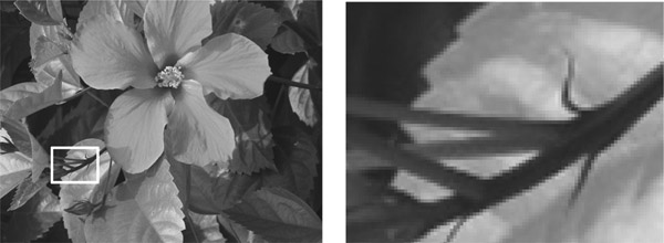
NOTE In a digital video signal, these picture elements are called pixels, short for picture elements (Figure 2.3).
In the television system that was used in the United States, the electron beam would scan back and forth across the target 525 times in each television frame. Thus each frame in the television signal was composed of 525 scan lines. It did not matter what size the camera was or what size the pickup tube or monitor was. The total number of lines scanned from the top of the frame to the bottom of the frame would always be 525.
The image created in the video camera had now been turned into an electronic signal of varying voltages. As an electronic signal, the television image can be carried by cables, recorded, or even transmitted through the air.
Displaying the Image
The varying voltages generated by the camera could be converted back into light. This electrical energy powered an electron gun in the television receiver or monitor. That gun sent a stream of electrons to the face of the picture tube in the receiver. Changing voltages in the video signal caused chemical phosphors on the inside face of the receiver tube to glow with intensity in direct proportion to the amount of voltage. The image that originated in the tube camera is thus recreated, line by line. Motion and detail were all reproduced.
Camera Chips
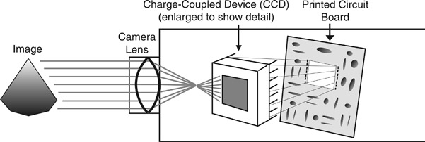
Over the years, the pickup tubes and the scanning yokes needed to drive the tube cameras have been eliminated and replaced by light-sensitive chips (Figure 2.4). There are two technologies commonly used for chip camera pickups, CCD and CMOS. CCD is a charge-coupled device. CMOS is short for complementary metal – oxide–semiconductor. First found in still cameras, this technology is now also common in video cameras as well.
A CCD is a chip that contains an area, or site, covered with millions of tiny capacitors or condensers (devices for storing electrical energy). There are millions of individual sites on image sensor chips. Often a chip is rated by the number of “megapixels” or millions of pixels it contains. This chip came out of the technology that was developed for EPROM (Erasable Programmable Read-Only Memory) chips. They are used for computer software where updates or changes can occur. When the information is burned onto an
EPROM, it is meant to be semi-permanent. It is erasable only under high-intensity ultraviolet light.
In a CCD camera, the light information that is converted to electrical energy is deposited on sites on the chip. Unlike an EPROM, however, it is easily removed or changed. The sites are tiny condensers that hold an electrical charge and are separated from each other by insulating material. This prevents the charge from leaking off. The chip is very efficient and can hold the information for extended periods of time. When the sites are done being exposed, the charges they collected are moved to adjacent holding cells ready to be passed onto off-chip processing.
CMOS chips are similar to CCDs but have amplification and scanning circuits built directly into the image capture chip. Combining some of the circuits makes it possible to produce less expensive cameras. However, as they transfer the image as it is being photographed, an artifact known as “rolling shutter” may occur. For this reason, high-end cameras still use frame transfer CCD chips.
Types of Chip Cameras
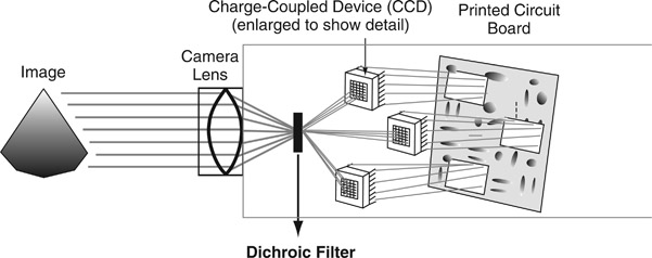
Chip cameras can be found in many forms, from the tiny camera in phones to the largest studio cameras in film and television production. Inside the chip camera, light coming through the lens is focused on a chip. In the case of cameras that use multiple chips, light entering the camera goes through a beam splitter and is then focused onto the chips, rather than passing through a pickup tube or tubes. A beam splitter is an optical device that takes the light coming in through the lens and divides or splits it. It directs the light through filters that filter out all but one color for each of the chips. One chip sees only red light, one only blue, and one only
green. The filters are called dichroic because they filter out two of the three colors. These chips are photosensitive, integrated circuits (Figure 2.5).
When light strikes the chip, it charges the chip’s sites with electrical energy in proportion to the amount of light that strikes the chip. In other words, the image that is focused on the chip is captured by the photosensitive surface as an electrical charge. This electrical charge is then read off the chip. The technology behind these chips allows them to shoot bright light without overloading. However, if the light is bright enough, the charge can spill over from one site to the next. This can cause the edges of an object within an image to smear or lag.
To prevent this, an optical grid or black screen is laid over the face of the chip so that between the light-sensitive sites there is both insulation and light-absorbing material. To capture the information stored on the chip, the chip is scanned from site to site, and the energy is discharged as this happens. A numerical value is assigned as each site is scanned, according to the amount of electrical energy present. This is part of the digitizing process, as the numerical value is converted to computer data for storage and transmission.
Many cameras use a single-chip design. The single-chip camera has filters over each photo site that pass only one color; red, blue or green. The most common method for this uses a format called the Bayer filter, which is an arrangement of the colors in a pattern that features twice as many green pixels as red or blue. This accounts for human vision, which is more sensitive to the green region of the color spectrum. In a single-chip camera, there is no need for three chips and a beam splitter.
Typically, the larger the size of the chip in the camera, the better the image quality. For example, a camera with a ⅔ inch chip will capture a better quality image than a camera with a ½ inch chip.
NOTE During the digitizing process, certain artifacts can occur in the video that can be a problem. Through image processing in the camera, these artifacts can be blended to make them less noticeable. These problems can sometimes be overcome by changing a camera angle or altering the lighting.