Video images are generated from a source, such as a camera or computer, and viewed on a device, such as a monitor. In order for the viewed image to be seen in exactly the same way and the same time frame as the generated or original image, there has to be a method for synchronizing the elements of the image. Synchronizing an image is a critical part of the video process.
Synchronizing Signals
As video moves from source to monitor, it is a series of electrical impulses. Whether analog or digital, by wire, fiber optic or through the air, the pulses that make up the picture follow each other one after the other. If you could freeze time then look at individual points along the signal path, you could measure individual voltages or find the bits to make pixels. The transmission medium then is a single dimension. It has only length, but not depth or width.
On the other hand, a single frame of video has both width and height. You can find a specific pixel from the signal path at some point between the left and right of the screen. It also is a measurable distance from the top and bottom. So a frame is a two-dimensional image. Motion pictures are made of the two-dimensional frames being shown one after the other. You can think of this as a third dimension.
Synchronizing signals provide the information to drive the scanning that changes the three dimensional images to a serial form for transmission and storage. The same signals can then be used to rebuild the pictures so they can be viewed.
When multiple sources are used in the same system, like the cameras in a TV studio, each must start their scan at the same exact moment. While most of video process has transitioned to digital signals, analog sync is still commonly used throughout studio and remote production. Although digital devices process sync in a different manner, the same sync signals described below are still used to co-ordinate the process.
Synchronizing Generators
A synchronizing generator, or sync generator as it is called, was the heart of the analog video system. Sync generators created a number of different pulses for driving the scanning of early analog equipment. As electronics transitioned from tubes to solid state, many cameras, recorders and processing devices began to incorporate their own sync generator circuits. The master house sync generator also provides a signal to devices that have their own sync generators. Devices that slave to that master signal are considered to be genlocked.
The heart of the sync generator is an oscillator that put out a signal called the color subcarrier, which is the reference signal that carries the color information portion of the signal (discussed in more detail later in this chapter). The frequency of the color subcarrier
is 3,579,545 cycles per second, rounded off and more commonly referred to as simply 3.58. Starting with this basic signal, the sync generator, through a process of electronic multiplication and division, outputs other frequencies in order to create the other pulses that are necessary for driving video equipment. These pulses included horizontal and vertical synchronizing pulses, horizontal and vertical drive pulses, horizontal and vertical blanking pulses, and equalizing pulses (Figure 4.1).
These pulses are often combined so that one signal will contain multiple synchronizing components. Combination signals are referred to as composite signals. Terms such as composite blanking and composite video refer to such signals.
NOTE It is the composite sync signal that remains important today.
Synchronizing Pulses
For older analog systems, the sync generator put out both horizontal and vertical synchronizing pulses. These synchronizing pulses ensured that all of the equipment within the system was in time or synchronized. Horizontal and vertical synchronizing pulses are part of the composite signal, so they can be easily fed to any piece of equipment that requires a sync reference signal.
Horizontal synchronizing pulses appeared at the beginning of each line of analog video. They assured that monitors and receivers were in synchronization on a line-by-line basis with the information that the camera was creating. Vertical synchronizing pulses appeared during the vertical interval. These pulses assured that the retrace was taking place properly, so that the gun was in its proper position for painting the beginning of the next field.
The composite sync signal ensures that each piece of equipment is operating within the system on a line-by-line, field-by-field basis. If equipment is not synchronized, switching between images can cause the image in the monitor to lose stability. For example, dissolves and special effects can change color or shift position. Character generators or computer-generated images might appear in a different position in the image from where they were originally placed.
Color Subcarrier
As mentioned above, with the advent of color television, the color subcarrier signal was created to carry the color information. This signal became the most important signal of the sync generator. In the digital world, color subcarrier is no longer part of the video signal. However it is still used as the base frequency that a sync generator uses to create composite sync.
The frequency of the color subcarrier is 3,579,545 cycles per second. This frequency must be maintained within plus or minus 10 cycles per second. If this frequency changes, the rate of change cannot be greater than one cycle per second every second. The exactness of this specification has to do with the sensitivity of the human eye to changes in color. As this color subcarrier signal was the reference for color information, any change in the frequency would cause a shift in the color balance. The color subcarrier is also used as the main reference signal for the entire video signal. If the color subcarrier is incorrect, then all the signals in the television system will be affected.
Cross Pulse Display
On a professional video monitor, the image can be shifted horizontally to make the horizontal blanking period visible. The image can also be shifted vertically to make the vertical blanking interval visible (Figure 4.2 (A)). When the image is shifted both horizontally and vertically at the same time, the display is known as a cross pulse or pulse cross display. A cross pulse display is a visual image of what is represented electronically on a waveform monitor. This display shows several of the signals created in the sync generator (Figure 4.2 (B)).
Other Signal Outputs
Sync generators often provide test signals, such as black burst and color subcarrier outputs. Some of these outputs may appear on the front of their face plates for ease of access. Those same signals are available at the back of the unit as well. Additional test signals are discussed later in the book.
Vertical Interval Signals
The NTSC analog video image was 525 lines, 480 of which represent picture information, referred to as active video. The remaining lines in the vertical interval were used for synchronizing information. Test signals were inserted in the vertical interval as well. While not
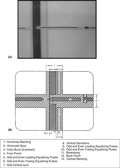
Figure 4.2A and B, Cross Pulse Display of an Analog Signal
part of the active video, they were a valuable part of the composite signal.
These signals were usually created by devices connected to one or more of the outputs of a sync generator. These extra signals could then be inserted in the vertical interval. These signals included vertical interval test signals, vertical interval reference signals, closed captioning, teletext, commercial insertion data, and satellite data.
In the case of the vertical interval test signals (VITS), a test signal generator could create one-line representations of several test signals. These one-line test signals were inserted in one of the unused video lines in the vertical interval. The VITS could be displayed on an oscilloscope. This test signal provided a constant reference with respect to the active video contained within the frame.
The vertical interval reference signal (VIRS) was developed to maintain color fidelity. Small differences in color synchronization can occur when signals are switched between pieces of equipment. The VIRS provided a constant color reference for the monitor or receiver. Without the VIRS, the color balance of the image might change.
Closed captioning was originally developed so the hearing impaired could watch a program and understand the dialogue. In closed captioning, the receiver took the information from the vertical interval and decoded it into subtitles in the active video. Closed captioning could also be used in environments where the audio may not be appropriate or desired. Technically, since closed captioning appeared on line 21, which is active video, the data was not truly in the vertical interval.
Commercial insertion data can be used to automatically initiate the playback of a commercial. This can eliminate the possibility of operator error. The data are designed to trigger the playback of the required material at the appropriate time, as well as for verification that the commercial was broadcast as ordered.
Satellite data contains information about the satellite being used, the specific channel or transponder on the satellite, and the frequencies used for the audio signals.
Digital Data Bursts
Digital signals do not require blanking, vertical and horizontal sync signals. Instead each line has two short data bursts called the Start of Active Video (SAV) and End of Active Video (EAV) (Figure 4.3, Plate 1). This leaves the time in the signal flow used by analog sync signals available for other uses. It is during this time that audio information (up to 16 channels) and other ancillary data information is
inserted. If you examine the cross pulse display of a digital signal, you can see the audio information forming in the area between each line. This is called the horizontal ancillary data area, or HANC. The types of signals once inserted in the vertical interval of analog signals are now carried in the vertical ancillary data area (VANC) of the digital signal.
Tri-Level Sync
While the SAV and EAV data bursts work inside the digital signal to control scanning and framing, there still needs to be a signal that can be used to synchronize devices that must work as a system.
As HDTV was developed, a matching analog sync signal was created to drive the scanning of the now obsolete analog version of HD. This signal is called tri-level sync. It is a modification of traditional sync, which is now often call bi-level snyc to differentiate it from the newer form. Most digital HD equipment will work with either type of sync, and most TV facilities still use the bi-level form for most purposes. Some HD equipment may not accept bi-level, so you will find tri-level sync outputs on sync generators as well as traditional sync outputs.
In summary, the blanking portions of the video signal, both horizontal and vertical, carry critical information. In addition to synchronizing, the blanking periods are used to carry other data that enhance the quality and usefulness of the video signal.