In order to ensure a video signal looks its best on the receiving end, it must be set up and monitored on the sending side. There are two general aspects that are important when preparing a video to broadcast or export: monitoring the image and measuring the signal. The video signal can be viewed and measured on a variety of test equipment such as scopes, which will be addressed in the following chapters. The actual video image, however, is viewed on a monitor. The monitor is part of the group of test equipment used to judge the quality of a video image. Adjustments made to a monitor do not affect the video signal itself.
Types of Monitors
Monitors are available in a number of quality grades and a broad range of prices. At the low end, for a few hundred dollars, are sets sold as consumer television displays. While these can produce a very good image, they do not have the tools necessary that are part of a professional monitor. Their color is often set to be pleasing rather than accurate to make them more appealing for purchase.
In the middle range are professional monitors that have better color rendition and control. They can cost several times what a consumer set does, primarily as there are no efficiencies in mass production to help defray the cost of the additional features. These monitors are good for most general television production applications. They may be stand-alone single displays, or they may be multi-image processors that can display several small images on a single large monitor. This type of display is often seen in control rooms where many images must be viewable at the same time.
Finally, there are top quality monitors used for critical color judgments. These are often found in finishing editing suites and in color correction applications. Called “Grade 1” or “Reference” monitors, it is not uncommon to see these units costing thousands of dollars each. If you are making the final color judgments on high-end or broadcast productions, these are the units to seek.
Video Displays
The original method of displaying video was through the use of the cathode ray tube (CRT). This type of display is called direct view, with the receiver or monitor being rack-mounted or placed on a stand. The screen size ranges from a few inches up to a fifty-inch picture tube. CRT’s are no longer manufactured, replaced by several different flat screen technologies described below.
LCD
The LCD (liquid crystal display) uses a fluorescent backlight or, in newer versions, LEDs (light-emitting diodes) to send light through liquid crystal molecules. On the display screen there are red, green and blue pixels that are connected by an array of wires. By applying voltage to the pixels, backlight can either be allowed or prevented passage, thereby illuminating the screen. As most of the light generated by the backlights is blocked at any given time, these displays draw quite a bit of power. LCDs are not perfect in blocking all the light when they should be black, which makes getting truly deep black images a challenge.
NOTE A new monitor technology called Quantum Dots is emerging as of the writing of this book. The future of monitors seems to be moving in the direction of being able to show a fuller spectrum of color, closer to what the human eye can see.
OLED
Organic light-emitting diode uses a film of organic compound that lights up when an electric current is passed though it. The film is between layers of electrodes that can be switched on and off independently. Red, green and blue elements placed either side by side or one in front of the other in layers provide the color. One big advantage of OLED technology is that it does not require a backlight. Each pixel lights independently. This greatly reduces the power necessary to operate the display when compared to LCD and LED displays.
Plasma
A plasma is an ionized gas in which some of the electrons have been disassociated from some of the atoms or molecules in a substance. These free electrons make the plasma electrically conductive so that it responds to electromagnetic fields. The plasma video display uses the ionized gas or plasma created by an electrical charge passing through it. In the plasma video display, argon, neon, and xenon are used to produce the colors and luminance. The video screen is composed of an array of red, green, and blue phosphors that are located between two sheets of glass. Each group of three phosphors composes one pixel. An electrical pulse is used to excite the phosphors causing the creation of plasma. The plasma emits ultraviolet (UV) light that causes the phosphors to glow. While plasma displays produce great pictures, their high cost and the commercial success of LCD and LED systems caused manufactures to abandon them in 2014.
Projection Systems
Projection systems are available as front-projection and rear-projection types. In a front-projection system, a video projector is used to illuminate a screen in much the same manner as film is displayed. The screen size can be as large as one hundred inches measured diagonally. Rear-projection systems generally have an internal projector and a mirror to reflect the image on to the viewing screen and are viewed in much the same manner as a direct-view CRT. The viewing screen is generally forty to eighty inches in size, measured diagonally. In the older type of projection systems, both front and rear systems used three CRTs—one red, one blue and one green—that are aligned to create a single image on the viewing screen.
The newer types of displays include Digital Light processing (DLP), liquid crystal display (LCD), liquid crystal on silicon (LCoS) and plasma.
DLP
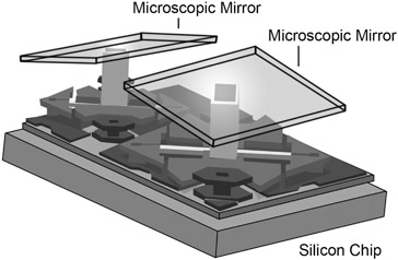
The DLP uses an optical semiconductor called a Digital Micromirror Device developed by Texas Instruments. The device is composed of millions of microscopic mirrors arranged in a rectangular array on a silicon chip that rotate or move thousands of times a second (Figure 7.1). They direct light toward or away from specific pixel spaces. DLP projectors can use three individual chips, one for each primary color.
There is also a single-chip version that works by focusing a high-intensity lamp through a condensing lens. The condensed light then passes though a six-panel color wheel that filters the light into red, green and blue. Each color appears twice on the filter wheel. The light then passes through a shaping lens. This shaped light source focuses on the chip, is reflected by the microscopic mirrors, and then passes through a projection lens onto a screen. The movement and position of the mirrors creates the color image on the screen.
LCoS
The LCoS display is also a projection technique, used primarily for commercial projection systems. It is similar to the LCD except that it uses an extra layer of material. This layer is silicon, a highly reflective surface located behind the liquid crystal layer, and it increases the intensity of the light shining through the crystal layer.
It therefore transmits a greater amount of light than the LCD alone, creating a brighter image.
The Human Eye
The human eye is not an absolute measuring device; it is an averaging device. Eyes, like noses, get desensitized when exposed for too long to the same stimulus. As a result of looking at one or more colors for a long period of time, mistakes can easily be made when trying to color balance a video image. During setup, it can be helpful to look away periodically for a few seconds so the eyes don’t become desensitized. In the case of a long setup procedure, it might be best to walk away for a few minutes into a different room with different light. It is imperative to always apply setup procedures to the monitor in the same light conditions that will be used when viewing the video image.
Color Bars
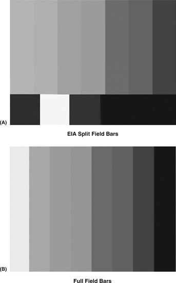
The test signal traditionally used to set up a video monitor is color bars. It is the international professional reference used to ensure that the color of the images that follow look the same on any monitor as they did when they were created. The color bar signal contains everything needed to set up a CRT type color monitor and the signal itself, which will be discussed in the following chapter (Figure 7.2, Plate 6).
There are several varieties of color bar displays approved by the International Organization for Standardization (ISO), the agency that sets international standards. Different color bars have different elements. Although the elements may differ, all color bar signals have the same basic chrominance and luminance references.
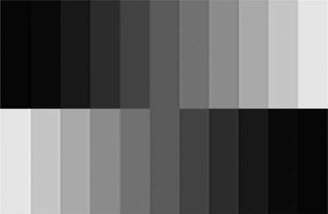
Gray Scale
Color bars do not have a reference to set the contrast or bright part of the picture. For that a test pattern called a stair step or gray scale is very useful (Figure 7.3). This pattern can be made by a test generator or may be found on video calibration disks.
Setting up Monitors
Because analog CRT type monitors were subject to drift in their setup, users were encouraged to check the settings of their monitors at least once per work shift. While current displays hold their setting quite well, differences in room lighting may require adjusting monitors to produce the best picture. While not an issue in control rooms or edit bays, monitors used for field work should be checked when there is a significant change in the amount of light in the environment where the monitor is being used.
If you are using a consumer product as your monitor, it is important to do a complete setup when you first get the monitor. Consumer equipment is most often set to give the brightest picture possible in a brightly lit room like a store. As you are unlikely to be working in that bright of a space, setting the monitor for the light level you are working in is critical.
Computer monitors are used by many video makers as their main method to view their work. Computers are not designed for just video work, and may not present an accurate display of your material. In addition to the settings for your monitor, you will need to make adjustments to your computer’s video hardware. Find the software control panel for your video card and follow the calibration instructions, paying special attention to the gamma setting.
Gamma Curve
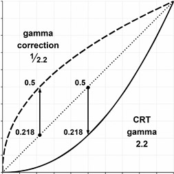
Gamma is the property of displays that deals with the relationship of the amount of light produced for the amount of voltage applied to the display. Older tube type displays were non-linear, meaning that it took different amounts of change voltage to see a difference in the dark part of the picture than in the lighter parts. This takes the form of a curve as in Figure 7.4.
Early broadcasts fixed this problem in the camera, applying an opposite curve. By building this circuit into the camera rather then each TV, sets could be priced more inexpensively. Now a larger range of display types are used, each with different gamma characteristics. Our video, however, still carries the correction factor for CRT’s. So the displays must now be adjusted to suit the video gamma, which is normally set at 2.2 when you are calibrating your computer’s video card.
How to Set Up a Monitor
Monitors designed for video evaluation are designed to be as neutral as possible, so that they can be used to judge the video signal they are displaying. Consumer equipment, however, is configured to produce the most “pleasing” possible picture. Should you choose to use one of these devices in a professional situation, you will need to make some initial settings.
First, check and set the color temperature. As anyone who has forgotten to white balance a camera can tell you, light can vary from a warm yellow to a cool blue. Flat screen TV type monitors often have controls to set them to be warm or cool. Often called “picture mode” or something similar, you need to find the control that adjusts color temperature and choose the most neutral setting. This is easiest when looking at a black and white picture. If your monitor offers color temperature options labeled with actual values, the proper one is 6500K or D65. This is the approximate color of daylight.
Next find the detail or sharpness control. The purpose of this function is to make images look sharper. This is done by adding a thin white border around high frequency or detailed information in the picture. While this often produces a seemingly crisper image, it will be a problem if you are trying to evaluate a shot for focus or depth of field. Turn this down to a very low setting, if not off completely.
Then switch off the dynamic contrast. This function of consumer monitors is to try and increase the contrast range of the monitor. By dynamically changing the brightness of the backlighting system to match overall scene brightness, manufacturers can claim better contrast ratios for their displays. However, if you are using a monitor to judge the quality of your work, this function may mask problems in your shot.
Finally, set the overall backlight intensity of the monitor for light level in your room. If you are working in a dark room, you do not need the full light output of the monitor. Setting the proper amount of backlighting will allow you to get proper setting for brightness and contrast and ease eyestrain. There is not an exact value for this, but you should set a level of backlight that allows you to examine the highlights in your material and lets the blackest parts be as dark as possible.
Setting the Brightness and Contrast
The most important aspects of changing a monitor for different room lighting are the brightness and contrast settings. The brightness setting primarily affects the dark part of the images, while contrast is the brighter parts. This is best done with a black and white stair step or gray scale pattern as shown in Figure 7.3.
Start with the contrast control and adjust the monitor so that the brightest two chips on the stair step pattern are just different. It is often easiest to do this by turning the control way up and then slowly lowering it, watching for a difference to appear. Next use the brightness control to set the two darkest chips so they are just different. After you set brightness go back and check the contrast with the white chips again. The controls interact and it could take a few back and forth adjustments to get the setting just right.
Setting the Color
The next step is to set the amount of color and the hue (or tint) of the color. To do this you need to use SMPTE bars and be able to look at just the blue channel output. Professional monitors have a blue-only setting that turns off the red and green channels to the monitor. Consumer equipment and computer monitors most often do not have that setting. To set the color and hue on a consumer monitor, you will need to use a blue filter held over your eye that completely blocks the red and green light. You can experiment with several thicknesses of blue lighting gel or photographic filters until you find a combination that works.
In a SMPTE color bar pattern, there are small chips of color located below four of the color bars. These chips are arranged so they contain the same amount of blue content as the bars above them. Adjust the color control so that the outer bars and chips (the white and blue) are the same shade. Then adjust the hue control so that the inner bars (magenta and cyan) match. Again, you may find a small amount of interaction between these settings.
Color Image Tools
The above procedures will do a good job of getting a decent display. However, for an even better result, there are tools designed to help set up monitors.
The first is a video calibration Blu-Ray disk. These disks have test patterns and instructions designed to help set up home theater systems. They will also help achieve a non-professional monitor setup. As a bonus, some come with the blue filter you need to set color and hue on monitors without the blue-only function.
For the most accurate setup, however, a device called a Colorimeter should be used to properly balance the RGB values of the display. Colorimeters are a form of light meter that is held against the surface of the display. These devices let you measure and balance the amount of red, green and blue light produced by the display.
Wrap Up
Which display to choose requires a bit of compromise. The obvious answer is to select the best quality picture that a budget allows for each application. The level of quality expected for a critical evaluation unit is entirely different than that for a monitor that is only necessary to verify the presence of a signal.