Chapter 4
Documents Produced Using Office Technology
4.1 Introduction
Having explored in depth the processes of writing and signing in Chapters 2 and 3, in this chapter the emphasis will be on the ways in which the written word is put on paper by means of mechanical devices. In order to understand how a forensic examination of documents produced with such devices is made, it is first necessary to understand the mechanisms of the machines themselves. The mechanisms together with the inks used dictate what the output looks like on paper. From this, it is possible to shed light on possible avenues of forensic evidence that can determine which kind of mechanism was involved in the production of a document and potentially which individual machine was responsible.
The underlying principles for examining machine-produced documents are essentially similar irrespective of the type of machine. The first step is to understand in general terms the manufacturing of the device. Ideally, all newly manufactured devices and their components should work perfectly and all be identical to one another, be they laser printers or fax machines or whatever. (Whether that is the case depends on the quality control systems in place as goods leave the factory.) As soon as machines start to be used, then wear and tear will start to play a part in the deterioration of that device. Since the use that devices receive will vary, the pattern of deterioration caused by wear and tear has the potential to make each machine uniquely identifiable providing there are ways to discern the effects of the changes from an examination of the documents produced from it. This is the single most important general principle in the identification of documents produced by machines.
In the not too distant past, machine-produced documents tended to be more frequently encountered in office and business settings as opposed to the domestic market, where such devices tended to be expensive and not needed in the days before the personal computer. It is true to say that quite a few homes did have a typewriter, for instance, but this was nowhere near as universal as the presence of the PC and associated printers and scanners is today.
During the transitional period from the typewriter to the computer printer (roughly speaking the 1980s and 1990s) computer printers started out being very expensive but increased demand and technological improvements led to a huge drop in price and made such machines commonplace and affordable to most. The transformation in less than a generation has been considerable and poses new challenges for the forensic document examiner.
4.2 Typewriters
The typewriter was invented in the late 1800s and its presence increased steadily in the business market into the 1980s, after which time there was a fairly rapid decline to the point where typewriters are now rarely encountered in casework. Rarely encountered, but just occasionally a typewriter features in a case and there remains the need for a document examiner to be able to examine the documents and, where relevant, the typewriter to interpret findings.
The first machines that were made were so-called typebar typewriters. These devices had the typeface placed on a series of about 40 typebars arranged in a basket-like configuration (Figure 4.1).
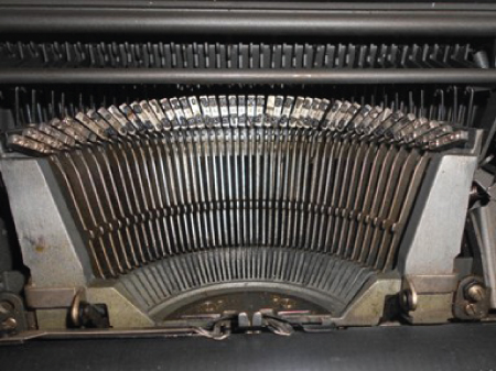
Figure 4.1 The arrangement of typebars.
The typebars were made of metal. The ends of the typebars were fitted with metal pieces on which the typeface was present. Usually, each piece of metal had two characters present, such as the lower case (small form) and the upper case (capital form) of a given letter (Figure 4.2), or the various numerals and symbols which are largely retained on the modern computer keyboard.
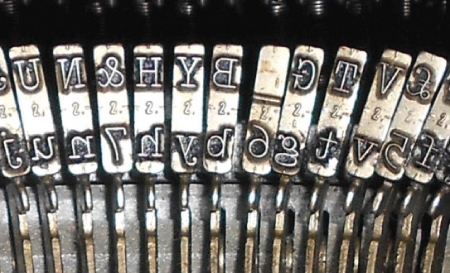
Figure 4.2 Two characters are present at the end of each typebar with the upper one accessed by using the shift mechanism (x3 approx.).
The shapes of the various letters, numerals and other characters comprise the font style. Certain fonts, such as Times New Roman, were widely used and became almost the expected style for use in business letters. But as time went on and more modern ideas came in, fashions in font style changed and more became available. Fonts tended to become simpler and some had no serifs, the small leg-like structures at the ends of characters (Figure 4.3).

Figure 4.3 Letter m in a font with (left) and without (right) serifs.
While it was theoretically possible to take a typebar typewriter into a workshop and get the metal pieces that had the typeface on removed and new ones put in their place, this was rarely encountered and to all intents and purposes the typeface could be considered fixed.
The typewriter mechanism in most typebar typewriters was mechanical and manually operated (as opposed to electric devices). The depression of a key on the typewriter keyboard would require sufficient force to move a series of levers joined to the key and linked to the relevant typebar. If the key was hit fairly lightly, this would be translated into a fairly faint impact of the typebar onto the paper. A heavier depression of the key would create a greater impact on the paper. The typebars impacted onto the paper through a fabric typewriter ribbon that made the impacting typeface make an inked mark (the relevant typed character) on the page. The paper was held around a cylindrical roller (or platen) (Figure 4.4). Rotation of the platen would move the paper with it such that at the end of a line of typescript, the paper would wind around the platen ready to start the next line a short distance below the previous line (having essentially the same effect as pressing the ENTER key on a computer keyboard). Most typewriters had a lever to set the distance between lines of typescript at so-called single spacing, double or triple spacing (with a large distance between lines of typing).
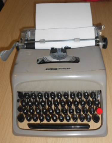
Figure 4.4 Paper inserted round a typewriter platen.
As each key stroke was made the platen (and hence the paper) would move laterally a fixed distance. This ensured that each typed character had its own place a fixed distance from the characters either side of it. This inter-letter spacing was fixed for a given typebar typewriter, although different machines could have different spacings, typically 10 characters per inch (often called pica spacing) or 12 characters per inch (often called elite spacing).
The movement of the typebars themselves could vary depending on the quality of the machine. The typebar was a moving and potentially slightly flexible arm bearing the typeface at its end. Any movement of the typebar (for example from side to side) might alter the exact appearance and position of the typed character on the paper. For example any twisting of the typebar might cause the character to print unevenly (perhaps printing heavier at the top of the letter for instance).
In general, large office machines were designed to withstand a lot of heavy use and tended to be the most reliable in terms of the precision of the typescript produced using them. Smaller machines (often sold as portable devices for home use) were sometimes less robust and there was a tendency for them to produce a somewhat more erratic and less precise typed product.
The fabric ribbons used in typebar typewriters were made from a woven material impregnated with ink. The ribbons were intended to be reused. New ribbons would produce a fairly well-inked, dark typed character, but with use, the amount of ink present in the ribbon would decrease and cause a correspondingly grey typed character. The weave pattern of the ribbon material and the diminution of ink present would tend to yield a typed character that became less clear in its appearance with a fuzzy outline (Figure 4.5).
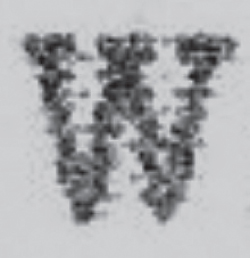
Figure 4.5 Close up of letter w showing the weave pattern from the fabric ribbon (x15 approx.).
In manual machines, the force with which a typewriter key is depressed is passed on to the typebar impacting onto the paper. (In electric typebar machines the keystroke led to an electrical signal going to the typebar and hence the force of the keystroke did not get translated into a heavier impact of the typebar onto the paper.) If the typed character was small, such as a fullstop, the force on that small character could punch through the paper surface, whereas the same force on a large character, such as a letter W, would be dispersed over a larger area and would not normally puncture the paper.
The evenness with which typewriter keys were depressed was to some extent related to training as a typist. Experienced typists had an even pressure that was generally reflected in the even ink deposition from the ribbon – the various typed characters were more or less of a similar ink colour intensity. In contrast, inexperienced typists were liable to depress typewriter keys with variable force leading to some characters being more intensely inked than others. This raised the possibility of being able to assess the quality not of the machine but of the operator, the typist. Skilled typing shares some similarity to handwriting in that it becomes a highly learned and automated skill with a variety of habits, such as the way that documents are formatted (Lines & Carodine, 2005).
The appearance of characters typed using a typebar typewriter can vary from one occasion to another depending on a number of factors. Obviously the typeface itself is constant, but the distribution of ink on a fabric ribbon may vary, the pressure with which the typeface comes into contact with the paper may vary depending on how hard the key is hit by the typist, and if the document is a carbon copy (used traditionally when typists wanted to produce multiple copies of a typed document – see Box 4.1) then it may be less well-defined in appearance.
If a small portable typewriter was used rather than a larger, heavy duty office machine this might lead to a more variable output from the less mechanically robust machine. So although there is no natural variation as there is in handwriting and signature production, there can still be variation in the both the clarity of the typed characters and their positioning on the line of typing from one occasion to another. This could affect the forensic examination if, for example, a letter t on some occasions appeared a fraction longer to the left and on others appeared a fraction longer to the right; in the absence of the typewriter itself, caution would be needed in interpreting this.
The typefaces used were sometimes supplied by separate manufacturers who would supply the same typeface to more than one typewriter manufacturer. As a consequence the same typeface could appear on typebar typewriters made by several different typewriter manufacturers. Over time a large number of typefaces became available for use on typebar typewriters. A number of typeface collections (see Box 4.2) were created with the purpose of enabling forensic document examiners to identify the make of machine used to type a document. In casework, requests for determining the manufacturer of a piece of typescript of unknown origin (so as to give investigators an idea of what to look for) were once common.
The use of collections of typefaces was aimed almost exclusively at providing information to an investigator as to the make of machine involved in typing a document. Such databases had almost no value when comparing questioned and specimen typefaces, although they did have one useful function, namely to provide reference materials for examination. For example, if a questioned document showed a small letter m without a serif on its middle leg, should that be evidence that the serif was broken? Use of the reference collection of typefaces would show that some typefaces were designed with a letter m with no serif on its middle leg and hence the apparent broken serif might in fact be a design feature.
4.3 The forensic examination of typebar typewriters
Cases usually fall into one of two types. The first type requires a comparison between typed documents with samples produced on a particular typewriter with the machine being available for inspection. The second type of case is to show that a number of typed documents have (or have not) been typed on the same typewriter (there being no typewriter to examine).
When available, it is always good practice to examine a typewriter (or indeed any other device involved in forensic cases). The examination of a typewriter often follows a set routine. It is important to note the obvious features such as the make and model. The majority of typewriters are given serial numbers by their manufacturers which makes identifying the machine easier and can ensure that the machine examined in the laboratory by the document examiner is indeed the machine that ends up as a court exhibit some time later.
Most machines have a ribbon in place when submitted for forensic examination. The colour of the ribbon is generally just black but some typewriters were designed to be able to use two-colour ribbons, typically black at the top and red at the bottom with switching between colours made possible by moving a lever to slightly alter the position of the ribbon in the machine.
As noted above, the typescript produced by a typewriter may not always be crystal clear and there may be uncertainty about the fine detail that has been obscured by, for example, a fading ribbon. Direct examination of the typeface (on the ends of the typebars) using a hand lens will usually resolve any uncertainties.
Examination of the typeface can first and foremost determine whether or not it has been damaged. The typeface of a typebar typewriter is made of metal and it is therefore generally robust and not very likely to break. However, heavy use (exacerbated by heavy handed typing) can eventually lead to damage to the typeface. Such damage is very often focused on the weakest part of the characters, namely the serifs, the small leg-like elements present in many fonts (Figure 4.7). The nature of the metallic material is such that breaks tend to be sudden and complete – one day the serif is there, the next it has broken off; there is no gradual deterioration with first some loss of metal and then more over time. In fact the metal will have been cracking over a period of time but this will not be apparent from the typescript. Eventually the crack becomes such that the serif is no longer secure and it breaks away.
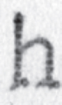
Figure 4.7 Close up of a letter h with top and bottom serifs on left side damaged (x15 approx.).
Damage of this kind is not uncommon, but on the other hand it is not by any means all that frequent. As far as the forensic document examiner is concerned, this is an ideal state of affairs since if no typeface ever deteriorated then that would make connecting typescripts to typewriters more difficult, and if such damage was too widespread many machines might show it and make it too commonplace to be significant. For the forensic document examiner, finding a damaged serif in some typescript is therefore of potentially considerable significance. Confirmation that the typeface has broken comes from an examination of the typeface on the typewriter that shows a break in the relevant part of the character where the serif used to be. Because the break is a fracturing process from the original smooth metal, the raw edge of the break appears uneven and under low power magnification this can be readily seen.
Damaged characters, then, provide the best evidence to link a typewriter to a document. But what if there are no damaged characters? As noted above, the positioning of typed characters on the page may be imperfect due to mechanical defects in such machines with typebars moving laterally or twisting, for example. The result is that typed characters may print to the left or right, above or below the line of typing or may ink more heavily in one part of the character than the other. Such misalignment defects are the next best source of evidence for the document examiner. Visualising misalignments can be done with the naked eye but it is helpful to use a grid of regular lines having the same inter-letter spacing as the typescript. Thus each character, if perfectly aligned, should fall into the centre of the grid boxes. However, the occurrence and variability of misalignments is often related to the type of typewriter, with more robust office machines generally showing fewer and less variable misalignments compared to smaller, portable machines that tend to show more misalignments of greater variability.
The next source of evidence is the cleanliness of the typeface. Paper fibres and typewriter ribbon ink often combine to produce a material that can accumulate into the typeface, especially filling in the closed loops of characters such as the letters a, b d, e, g and so on (Figure 4.8). Dirt accumulating in the typeface can be quite characteristic but it can also be transient, since it can either become so heavy that it drops out of its own accord or, if the typist is diligent, cleaned away using a small suitable brush.
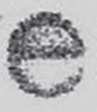
Figure 4.8 Close up of an infilled letter e (x15 approx.).
Finally, the mechanism of the typewriter itself may become defective. Perhaps the most frequent example being the shift mechanism used to move between upper and lower case letters, for example. If this mechanism does not function properly, it can lead to all of the capital letters being out of alignment. An examination of the typewriter will often confirm the nature of the defect.
In some cases, however, a typewriter may not be available to examine. In such cases, the examination of the typed document is exactly the same but the option of confirming some details by examining the machine itself is not available. This can limit the interpretation of the observations made.
Interpreting evidence in cases involving typebar typewriters is based on the experience of the document examiner. As noted above, the most compelling evidence generally comes from damage defects, then misalignments, then dirt and mechanism defects. A number of considerations will show the basis for assessing the evidence. There are many typewriter manufacturers using different typefaces. If the typeface matches then that is already some evidence of a link between a document and either the typewriter or another document. But a match is, as noted above, a somewhat imprecise concept when there may be uncertainty about some tiny details of character shape obscured by a grey weave pattern from a ribbon. For this reason it may be better to use the notion of no discernible difference between the questioned and specimen typescripts in terms of the typeface. Likewise, the closeness of any similarity in damage defects, misalignments and dirt must also be treated with caution when there is uncertainty of detail. However, given, for example, some damaged characters and some marked and consistent misaligning of characters, it is possible to reach strong conclusions. If there are just one or two misalignments or slightly dirty characters then the evidence is weaker. Many document examiners use the same scale of opinion to express the strength of evidence in such cases as described for handwriting (see Section 2.9.2 in Chapter 2).
4.4 Single element typewriters
The reign of typebar typewriters in the office environment started to come to an end in the 1960s and was more or less over by the 1990s. The production of typewriters with removable typefaces was a major development during this change. Two types of machine were produced, one with the typeface on a sphere (so-called ‘golfball’ typewriters) and those with the typeface on a wheel (so-called printwheel or ‘daisywheel’ machines). The typing element (sphere or wheel) was made of plastic and contained the typeface either in a series of rows and columns on the sphere or at the end of spokes on the wheel (Figure 4.9).
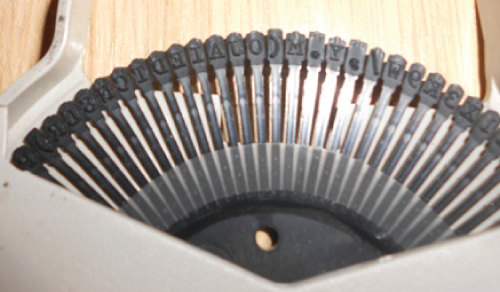
Figure 4.9 Showing a printwheel with one character at the end of each spoke (x2 approx.).
These machines were devised so that the typeface could readily be changed by insertion of a new typing element. If the typeface became damaged, the old typing element could be discarded or if the typist wanted to change the appearance of the typescript, an element with a different typeface could be used. Such machines required electricity to work (to move the typing elements into the correct position). Depression of the typewriter keys would lead to rotation of the sphere in two dimensions (to bring the relevant row and column into place) prior to the sphere being impacted via a ribbon onto the paper. In machines using a wheel, key depression led to a spinning of the wheel until the relevant spoke was in place and a small hammer hit the back of the spoke to impact it through a ribbon onto the paper.
The mechanisms holding the typing elements in place and the movement of the elements during the typing process as each relevant character was brought into position for typing were generally more robust and precise in their operation as compared to typebar typewriters. As a result, the character alignment along the line of typing is generally good for single element machines, with fewer and less marked misalignments. Very small misalignments can be visualised by overlaying pieces of typescript with a view to highlighting any tiny discrepancies. Where single element typewriters lose forensic evidence in misalignments they more than make up for it in relation to damage defects. The golfball and daisywheel elements are made of plastic. This completely changes the nature of typeface damage compared to that seen with metal typebars. The nature of the plastic material is such that it will crack with wear and small pieces gradually break away. This gradual breakup of the plastic gives rise to very distinctive damage features (Figure 4.10).
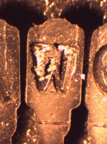
Figure 4.10 Close up of a severely damaged letter w on a printwheel (x10 approx.).
It might be expected that the use of a particular letter would be related to the observed frequency of damaged letters. Letter usage in English begins with e, t, a, o, i and n as the most common and ends with j, x, q and z as the least common. However, a survey of typing elements showed that there was no relation between those characters showing damage and normal letter usage (Allen & Hardcastle, 1990). A possible explanation for this is that microscopic weaknesses were introduced into the plastic of the typing element during the manufacturing process. Only during typing did these weaknesses manifest themselves, starting with a tiny splitting of the plastic gradually becoming worse until a piece of plastic fell away from the typing element.
The conformation in which the golfball and daisywheel elements were made alters from one manufacturer to another so that typing elements from one machine may not fit into a similar kind of machine made by a different manufacturer. One consequence of this is that the range of different typefaces available for one machine can vary to those for a different machine. Also, the interchangeable nature of typing elements means that the damage defects are in fact on the typing element and not an integral part of the machine as a whole. Thus, the forensic link between a document and a single element typewriter is via the typing element. Since a typing element can be taken from one machine and put into another (compatible) machine, this has to be reflected in the way in which the evidence is reported so as to emphasise the link to the element and not the machine into which the element was fitted at a particular time (such as when seized by the authorities for forensic examination).
Single element machines also were designed to be used at more than one inter-letter spacing. For example, machines capable of typing at ten characters per inch and twelve characters per inch were available as traditionally found on many typebar typewriters. A new option was also possible on single element typewriters, namely proportional spacing. In proportional spacing the distance between characters along the line of typing depends on the width of the characters. A wide letter such as a W would be given more space to the next character than a narrow letter such as an i, thereby making the typescript appear more like the print in a book or magazine.
Yet another development during this period was machines that were capable of storing (small) amounts of text in a memory. For example, text could be typed in and the typewriter would store it temporarily until a full line of text was input and then the whole line would be typed out in one pass. The text could be viewed on a small display and this enabled the typist to check it prior to typing it on the page. These were primitive fore-runners of the word processing capability that was to become universal with the personal computer. The ability to store text rather than instantly type it after each key stroke led to the possibility of aligning the right hand margin of the typing (justified text), which was achieved by the typewriter inserting small spaces between words so as to leave the right hand margin aligned. Different typewriters do this using different means of calculating where the spaces are placed, and this provides another possible way of differentiating between typewriters.
4.5 Typewriter ribbons and correcting typescript
Typebar typewriters traditionally used ribbons made of ink-impregnated fabric which could be re-used. The appearance of the typing was darker with a new ribbon but faded with time as the ribbon was both re-used and the ink tended to dry.
As typewriters changed, so new ribbons were introduced. The most common was the plastic film ribbon, which was made from a narrow plastic tape with ink on one side, the ink being somewhat waxy in nature. Typing caused all of the ink from the relevant area of the ribbon to be transferred onto the paper, leaving an impression on the ribbon. The ink appeared very black and gave a clear edge to the typed character in contrast to the grey and uneven edges observed with fabric ribbons. As a consequence of all of the ink being transferred, such ribbons were intended to be used once only. Text typed using such a ribbon could readily be deciphered by reading the sequence of characters typed from the ribbon (Figure 4.11). Ribbons were used by different machines in different ways. All were held in a cassette, but some ribbons wound from left to right and some right to left, some had one, some had two and some three rows of text on wider ribbons with characters reading both from left to right (or vice versa) and top row to bottom row (or vice versa). Thus whilst deciphering the text was straightforward, it was made no easier by this additional complexity. Attempts were made to automate ribbon reading since manually transcribing a whole ribbon was very time consuming and if it was urgent then it could hold up an investigation. However, image processing in this period was fairly primitive and the devices produced to read ribbons essentially produced simply an image of the text on a sheet of paper (via a video camera and printer) making it easier to manipulate but still requiring human intervention to decipher and make sense of it.
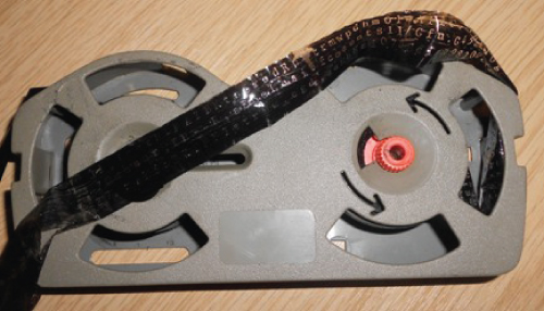
Figure 4.11 A carbon film ribbon showing readable text after use.
4.5.1 Correcting typed documents
Documents produced using a fabric ribbon were difficult to correct because the ink impregnated the paper surface. Removal involved either physical abrasion of the paper using an eraser or covering up the error using an opaque (usually white) correcting fluid and typing over it, a process that often led to the transfer of residual correcting fluid onto the typeface, exacerbating the accumulation of dirt into the type face. Some machines were fitted with a correction ribbon that was coated on one side with correction fluid, the idea being that by going back to the error, the typist would use the correction ribbon to cover up the error and then (using the normal ribbon) type in the correct character. This method was not widely used.
The nature of the ink used with plastic film ribbons was such that it did not tend to impregnate the paper as much as ink from a fabric ribbon would. Rather the ink could be removed fairly easily from the surface of the paper leaving little disruption to the paper surface. This principle was used by fitting typewriters with a correction ribbon that again consisted of a plastic tape but with one side having a sticky surface which, when brought into contact with typescript, would lift the ink off the paper surface and transfer it to the sticky side of the tape. This process led to corrections lifted from a document in sequence also being readable by inspection of the correction ribbon (Figure 4.12). Despite removal of the ink, the indentation of the typed character into the paper surface remained.
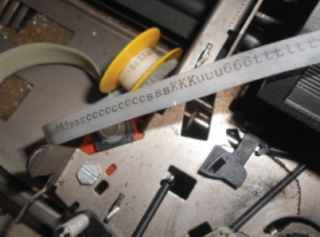
Figure 4.12 A lift off correction ribbon with removed characters present.
In order to determine whether a document has been corrected using a correction ribbon, the paper surface has to be examined carefully using an oblique light source to locate any impression into the paper surface. If, for example, several words have been corrected off the page, they will appear on the correction ribbon and also leave indentations on the page (although if new text were typed over the lifted off characters this could obscure the indentations to some extent). In principle, a sequence of characters removed from a page as shown by the remaining indentations can be linked forensically to a corresponding sequence of characters appearing on the correction ribbon of a typewriter.
4.6 Computer printers
Over a period of years, the typewriter as a standalone device became less and less used and the printer as an add-on to computers took over. During this transition period, a number of devices appeared and soon disappeared. Three have dominated the printer market. Initially, impact matrix printers were very widely used then, as technology and market forces developed, laser and inkjet became dominant.
4.6.1 Impact matrix printers
Computer printers generally create text and images from a pattern of dots or matrix. With impact matrix printers, the dots were created by impacting pins through a ribbon onto the paper. Because of the impact and the small cross-section of the pin head, the ribbons needed to be robust and fabric ribbons were generally used. A character of text was made up of a pattern of pin impressions. The pins were arranged in one or two rows in a vertical line in the print head, which moved from side to side across the paper. Typically there were nine pins in a row with seven above the print line and two below for the tails of letters such as g and y. The pins were fired in the correct pattern in order to make up recognisable letters and numerals (Figure 4.13). The order in which the pins were fired was determined by software.
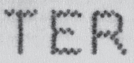
Figure 4.13 Matrix characters are made up of a pattern of dots (x15 approx.).
At the time of manufacture, the pins were equally spaced from one another and fell in a perfect vertical line. However, with use the pins could become bent and produce dots either displaced to the side, or too close to the pin above or below, effectively forms of misalignment defect that could provide a forensic link either between documents or with a particular printer and its print head.
For a time, impact matrix printers tried to move into the image printing market by using coloured ribbons, with a picture being made up of a series of passes using different colours on a ribbon. This was an extremely slow process and produced images of generally poor quality, and laser and inkjet soon took over. One advantage that impact matrix printers had over laser and inkjet was that the latter two are non-impact technologies. Where it was efficient to type onto multiple copy documents such as invoice sets, this could be done with impact matrix printers but not laser or inkjet.
4.6.2 Laser printers
Laser printers use toner technology similar to that used in photocopiers. The text or image is digital (determined by computer software) and it causes a laser beam to move across a light-sensitive metal cylindrical drum. The effect of the light on the drum is to change its electrostatic properties in the area concerned. This electrostatic charge can attract toner material which can then be transferred to a sheet of paper. The toner is fused to the paper using heat and pressure. The cylindrical drum is then cleaned of residual toner and is available for the next laser illumination.
Toner is a chemically complex material that has a granular appearance when viewed under low power microscopy (Figure 4.14). The toner is a solid material that tends not to diffuse very much into the paper surface but rather sits on it. The deposition of toner onto the paper is mostly in the image area (be it text or pictures), but there is usually a background scatter of individual toner particles across the paper surface too.
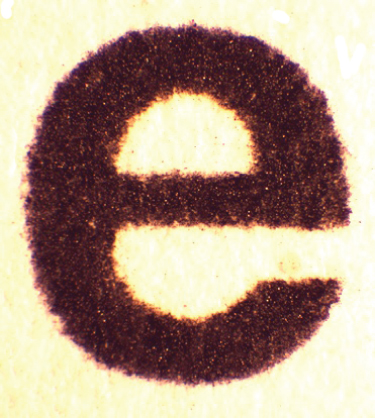
Figure 4.14 Letter e printed with a laser printer showing the molten appearance of raised toner on a paper surface (x30 approx.).
The cylindrical drum can, with use, develop small imperfections on its surface. These imperfections may attract toner particles such that each time documents are printed using it there will be a characteristic mark on the paper. The position and shape of such marks can provide forensic evidence linking documents printed using the same laser printer (specifically the drum) or linking documents to a particular printer. The drum marks are often very small and require low power magnification to be seen.
Given the likelihood of a background scatter of toner particles on a document, it is important to distinguish them from marks caused by drum defects. A difference between them is that background scatter is random whereas drum marks will appear repeatedly on documents, usually in the same relative position one to another on the document. The diameter of many laser printer drums is quite small such that to print a sheet of A4 paper requires perhaps three rotations of the drum. This will cause the drum mark to appear three times down the page spaced equally apart. Background scatter usually consists of one or a few toner particles, whereas drum marks often have a shape associated with them (Figure 4.15). Any shape to drum marks will add to their forensic significance.
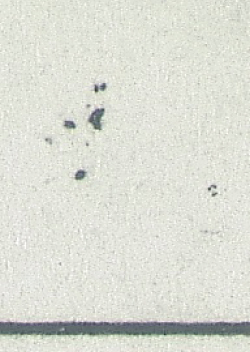
Figure 4.15 Close up of a group of drum defects (x15 approx.).
The use of colour in laser printers is made possible by having (usually) four toners available in yellow, cyan, magenta and black. These colours can be combined to produce many different colours. Each colour is printed onto the paper separately and in sequence. What might appear to be a solid colour to the naked eye will be shown to be made up of a combination of these colours when viewed under the microscope (Figure 4.16).
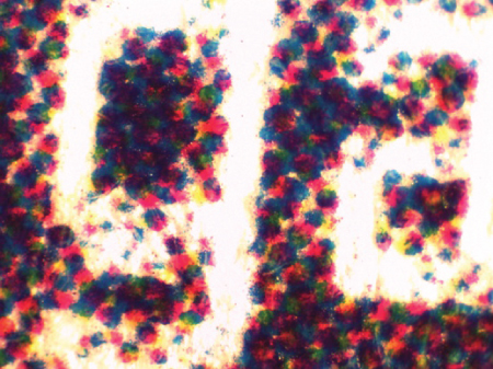
Figure 4.16 Close up of a colour laser print showing four colour (showing as shades of grey) dots (x30 approx.).
The chemical composition of the toner material can be analysed using a variety of techniques (see Section 4.8.3 below and also Chapter 7 for further discussion of the techniques used).
4.6.3 The forensic examination of laser printers and laser printed documents
The first step when examining a document is to establish whether it has been produced on a laser printer. This involves low power microscopy to confirm the presence of toner material. Next the document needs to be viewed under magnification for any potential drum marks. Since these can be tiny and not always easy to differentiate from background scatter, the identity of a drum mark may be confirmed by finding it repeated along the sheet of paper or by finding a mark in the same place on several pages of laser printed documents.
If a laser printer is available for examination it will be necessary to take some specimen sheets from it in order to compare any drum marks that it shows with those on the documents of interest. If drum marks are found, their forensic significance will depend on the number of marks and their distinctiveness (in particular, their shape). It is a matter of the expert's judgement as to the strength of evidence, but if there are sufficient distinctive marks then a very strong evidential link may be justified.
A number of factors must be considered in such cases, however (which will also be relevant when considering photocopy documents). In general, defects to any object are non-reversible unless there is some sort of intervention (such as the servicing of a machine). It is also likely that either some defects will become worse over time or that new defects will appear (or both). This will require careful interpretation when comparing defect marks on documents that were perhaps allegedly produced on a machine some months before the specimens were taken from it at the time of the examination. Given the tendency for defects to worsen and accumulate, there may be an apparent mismatch between the older documents and the newer (and hence potentially more defective) specimens. The reasoning process that needs to be used is this: Could the defect pattern shown by the older document be a forerunner of that seen in the contemporary specimen? If so, how much evidence (in terms of the number and distinctiveness of any defects) is there to support that possibility?
4.6.4 Inkjet printers
Inkjet printers build text and images from a large number of drops of ink. The ink used is a liquid ink that tends to soak into the paper's surface (Figure 4.17), in marked contrast to the solid toner that is used in laser printers that sits on the surface of the paper. This type of printer has become more and more commonplace as its cost has fallen and technology has improved, for example reducing drop size down to the level of picolitres (10-12 litre). The smaller the drop size, the better the quality of the image produced.
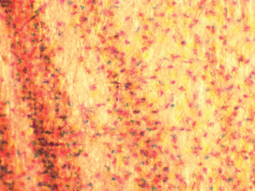
Figure 4.17 Close up of inkjet printing with ink absorbed into paper (x30 approx.).
There are two main kinds of inkjet printer that are differentiated by the method of delivering the ink to the page. Drop-on-demand printers will only produce a drop of ink when it is needed by the printer (as directed by software). Continuous ink printers send out a stream of droplets from the print head. When a drop is required at a particular location it is allowed to hit the paper, but when it is not required, the ink is deflected back into the ink reservoir to be recycled. The process of ejecting ink from the print head varies between machines but can include heat or piezoelectric crystals (which change their dimensions when charged with electricity and thus can expel ink from the print head). Print heads therefore contain both the mechanism for ejecting ink from the tiny pinhole openings in them and also reservoirs of ink.
As with laser printers, inkjet printers typically have four inks available (cyan, magenta, yellow and black) from which a vast array of colours can be made by using different combinations. What appear to be solid colours to the naked eye will be shown to be made up of dots of ink under magnification.
Inkjet drops that are ejected from the print head are usually accompanied by a halo of tiny micro-droplets (often called satellites), which also soak into the paper and create a fine haze around the main printed image/text. Because of the lateral movement of the print head across the page as it releases its ink droplets, the fine haze tends to be more apparent behind the direction of movement and hence under microscopic examination it is possible to determine the direction of travel of the print head across the page.
4.6.5 The forensic examination of inkjet printers
The appearance of the ink under low power magnification may show slightly differing colours of ink, different drop sizes and arrangements and possibly different degrees of satellite droplet formation. If microscopy is unable to distinguish between different inkjet-printed documents, chemical analysis may be appropriate.
The composition of inks used in inkjet printers varies between suppliers. The inks need to have a number of properties such as being fluid, remaining colour-fast on the paper and able to resist various environmental factors such as bright light and oxidation. The chemical analysis of inkjet inks can be carried out using a number of techniques, including electrophoresis (for example, Szafarska et al., (2011)), Raman spectroscopy (for example, Heudt et al., (2012)) and mass spectrometry (Houlgrave et al., (2013)). (See Chapter 7 for further discussion of these techniques.)
If it is not possible by the means available to distinguish between inkjet inks, the identification of a particular inkjet printer (or, more precisely its print head) as having produced a particular document is extremely difficult. Occasionally there may be disruption to the electronic signals to the print head causing a failure of ink release leading to, for example, a whole row of dots being missing on the printout. Such failures may provide some additional evidence to link documents either to each other or to the printer itself if available. As with many forensic investigations, it is easier to interpret differences between inks than it is to interpret similarities since the latter requires information relating to how common the particular inks are.
For the vast majority of cases, inkjet inks will be those widely available in retail outlets. However, it is possible for bespoke inkjet inks to be produced, for example to produce letterheads in house. Microscopic examination would still show the characteristic appearance of inkjet inks, but there might be only one colour present rather than the colour being a composite made up of cyan, yellow, magenta and black. By their very nature, such inks are far less frequently encountered and their presence may be of forensic significance.
4.7 Fax (facsimile) machines
Fax machines were originally developed to send text and images along telephone lines. In order to achieve this, the text and images had to be digitised and the digitised information could then be sent along the telephone line where, at the receiving end, the information was decoded to reconstruct the text and image for printing out. This was originally a fairly crude process due to limitations in the technology, and as a result the document that was received and printed out had poor resolution and a block-like appearance. Each small block of the printed fax copy document corresponded to the area of the original document, which was either coded as black or white with no intermediate grey tones. If there was more black than white in a block area it was coded as black and vice versa.
The printing process at the receiving fax machine was usually thermal, with the printer often set up with heat-sensitive paper. Each time there was a ‘black’ block to print, an electrode in the printer mechanism would heat up causing the paper in that small area to darken. Each time there was a white block then the mechanism would pass on leaving the paper still white. The crude nature of the ‘copying’ process and the mechanical process of paper moving through the printer led to frequent distortion of the printout in comparison to the original, including small dimensional changes.
Determining whether or not a given fax-printed document could have been printed on a particular fax machine may involve not only the examination of the printer but also the capability of the sending machine. This is particularly the case when the header or footer details that typically appeared on fax documents are relevant, since they are determined by the sending machine.
4.8 Photocopiers
The examination of photocopy documents can occur in a number of contexts. In the world of business, it is common for documents to be copied (first generation copy) and copied again (second generation copy) and so on. Forensic document examiners often examine aspects of a document from a copy. For example, handwriting or a signature may have to be examined from a copy document when the original is no longer available.
However, some cases involve the examination of photocopy documents in order to determine, for example, the photocopier on which it was produced. These cases are often very difficult because of the simple way in which a copy can be first, second or whatever generation, a process that introduces many potential pitfalls.
Photocopy technology today has become somewhat standardised, with machines using a solid toner-based system of creating the image or text on the paper. Solid toner has a characteristic appearance when viewed under a low power microscope – see Figure 4.14. In the past, some machines used a liquid toner, but such machines are almost never encountered any more.
The process of getting the toner onto the paper is essentially the same as for a laser printer described in Sections 4.6.2 and 4.6.3. The purpose of a photocopier was to simply reproduce in copy form a pre-existing image or text. By placing it onto a glass surface (usually called the platen) and using an optical mechanism, the details to be copied switch on or off a light source that is aimed at a light-sensitive metal drum inside the copier – as in a laser printer. In the past, this process was an analogue process involving mirrors and lenses. Modern photocopiers use digital scanning technology and this gives the potential to then manipulate the image using computer software prior to any print out of the copied details. In addition, the use of colour copiers has increased as the cost of the machines has fallen. Most colour copiers use four separate colours to generate the many different colours that can be achieved by mixing different proportions of cyan, magenta and yellow together with black. Different microscopic amounts of each colour are deposited on the paper in such a way that the human eye perceives the printed product as solid colour. It is only by using magnification that it becomes apparent that the print is composed of many small deposits of coloured toner particles.
Since photocopiers and laser printers use the same basic technology, the printed product when viewed under the microscope is the same. And since laser printers linked to a computer and scanner are to all intents and purposes using the same technology as inside a photocopier, then it is simplest to say that a document has been produced using toner rather than try and determine the exact type of machine used.
Photocopy documents are probably more likely to be copies of copies than laser printed documents if only for the reason that a laser printed document is often held as a computer file whereas an existing copy of a document is most conveniently copied again on a photocopier (thereby avoiding the need to scan and file on a computer). As a practical process, photocopying is quicker and more convenient.
4.8.1 The forensic examination of copy documents
There are a number of lines of examination that can be followed. Each case must be assessed on its own merits as to which approach is best.
The glass platen can be marked. Some marks may be transitory, such as a hair or some extraneous correction fluid. Glass is difficult to scratch but if it is scratched then this may provide a unique mark that becomes visible on the copy document.
Another important source of evidence comes from defects that accumulate on the light sensitive drum, which may become scratched and then such scratches will appear on the paper surface as small extraneous areas of toner. The shape and position of the marks will be highly characteristic as they are random in their occurrence.
The position of defect marks on the copy document may indicate whether the defect is caused by an imperfection on the platen or on the drum. The circumference of the light sensitive drum will affect how many turns it makes to produce a copy (which is also influenced by the size of the copy, be it A4 or A3, for example). The number of rotations of the drum to produce the standard A4 copy may vary from less than one (if the drum has a large circumference) to about three rotations (if the drum has a small circumference). Hence, a mark that repeats a couple of times down the page is strongly indicative of a drum defect. Also, if the defect is large and appears to have been caused by a hair, for example, this is probably a platen defect. However, a defect mark may not be visible if it happens to coincide with the printed details on a particular copy document. This might be a particular problem where the document has a lot of image and text and little unprinted (white paper) areas, such as banknotes.
If two copy documents share the same set of defect marks, then there is a temptation to assume that both documents were produced on the same photocopier. However, as noted above, it is easy for a copy of a copy to be made, and so the document examiner needs to consider the possibility, for example where two documents share some defect marks, that one copy document was created on a first photocopier and that this copy was subsequently copied on a second copier to produce the other copy document.
There are many routes to producing copy documents and it is often not possible to be absolutely certain of what has happened. In order to deal with this complex situation, there are a few ‘rules’ that can be used.
The first rule is that a copy document cannot be as clear as the document from which it is copied since the copying process is imperfect. Or put another way, it is impossible to create a clear copy from an unclear original document.
Another point to consider is that photocopiers usually can have the amount of toner reduced by lowering the contrast setting on the machine. The lowering of the contrast might produce a fainter copy such that some small or faint details that are present on the original do not show up on the copy.
Photocopiers do not always make exact 1:1 dimension copies. A dimension distortion of 1 or 2% is not unusual and this may be both down and across the sheet or just in one direction.
The changes in detail shown and dimensional distortions shown by copy documents may assist the expert in determining the relationship between various copies derived from the same original document. Of course, handwritten text is essentially unique and when copied there can be no question that ultimately there was only one original piece of handwriting. In contrast, modern computer-printed text can be printed from a saved computer file time and again, each printout being essentially identical to another, albeit the position of the text on the page or the type of printer used may vary.
4.8.2 Composite documents
Based on the many ways in which copy documents can be manipulated, it is possible to create a bogus document from genuine original components. Text, both printed and handwritten, and images can be copied either using a photocopier or by scanning into a computer. Manipulation of the information by cutting, pasting, cropping and the addition of new text or images can then produce a completely fraudulent document. Using the examination methods described above, the expert may be able to determine how the bogus document was produced or, failing that, it may be possible to suggest a number of ways it might have been produced.
4.8.3 Analysis of toner
Apart from an examination of the image content of a copy document, be it text or pictures or handwriting, the physical material from which it is composed, the toner, can be analysed. The toner typically contains colorant (dyes or pigments), a binder and other additives to ensure that it has the required chemical and physical properties.
Over the years in which photocopy technology has developed, a large number of analytical procedures to discriminate between different toners have been used (see Chapter 7). Amongst these are methods that fall into the categories of infrared spectroscopy (for example, Kemp and Totty, (1983)), x-ray fluorescence (for example, Trzcinska, (2006)), gas chromatography (for example, Egan et al., (2003)) and Raman spectroscopy (for example, Bozicevic et al., (2012)). However, there are a number of variants of these techniques and other analytical techniques that have also been used.
Analysis of toner clearly requires the availability of the necessary chemical equipment and the expertise to interpret the findings. In many cases a visual examination will be sufficient but chemical analysis may be a fruitful next approach if a visual examination does not assist the investigation.
From the descriptions in this chapter of methods for examining typed and copied documents, it is clear that some methods do not involve damaging the document, such as low power microscopy. However, chemical analysis can require removal of material from the document and these so-called destructive techniques, while usually only requiring tiny samples of material, nonetheless are altering the document. For this reason it is important that no destructive examinations are carried out without permission from an appropriate authority, such as the investigator. In addition, it is important to make a record (for example, a good quality photograph) of what the document looks like before any material is removed for analysis. The place(s) from which any material is removed should be recorded as this should then correspond to any (minor) areas of disruption to the document's surface that will be apparent afterwards.
In general, non-destructive techniques are quicker and cheaper than destructive techniques and often provide the evidence needed. However, analytical methods may be justified where no other evidence has been adduced.
4.9 Case notes in cases involving typed and copied documents
The amount of detail that needs to go into notes in cases involving typed or printed documents will vary from one case to another. In typescript cases involving traditional typewriters, it would be wise to place on file a photocopy of some documents as a record of the typeface. If there are any defects of the typescript, such as broken or misaligned characters, these can be highlighted on the file copy or sketched in the notes or both to indicate not just the presence of a defect but also its nature, be it a broken or a misaligned character. Inter-letter spacing should be noted for documents typed on typewriters. Any alterations to the typescript should be noted and the method of altering recorded (such as use of a correction ribbon) and any text that has been removed but that can be deciphered from its impression on the paper surface should be noted since it may be possible to link this to text found on a correction ribbon at a later date.
If a typewriter or printer is available for examination, then any model and serial numbers must be recorded so that at a later time it is possible to be sure about which machine was examined. Any specimens taken from typewriters or printers should be clearly labelled and retained on the file. If a typewriter ribbon is removed for deciphering, it is usually necessary to break into the cassette in which it is held – this process must be recorded appropriately.
With photocopy documents, it is a good idea to compare defect marks and their placement by using a clear plastic sheet and marking on it, using a suitable pen, where the marks are and, where appropriate, their shape. This transparency can then be overlaid on other documents to determine which defect marks correspond and which do not. If a copier itself is available, again any model and serial numbers should be noted. Obtaining specimens might require the placing of a blank sheet of paper on the platen and obtaining a series of perhaps 6–12 photocopies from the machine. The sequence with which they emerge from the machine should be recorded in case there are any unexpected changes in defect mark pattern with use.
If a questioned document is a photocopy and this is then photocopied by the expert to form part of the case record, it is crucial that the copies do not get muddled up. To minimise this risk, any copy document produced by the expert should be immediately marked as a file copy and the questioned document returned to a safe place where its identity is known (such as any packaging in which it was submitted).
Whatever the means of production of a typed or printed document, the observations that lead to the identification of the process must be recorded, which almost always will require a description of findings using microscopy. In addition, some print processes may be identified in part by features that they do not exhibit and so negative findings can also usefully be noted. For example, the absence of toner particles would rule out laser and photocopy processes or the absence of impressions in the paper surface will probably rule out conventional typewriters.
Having recorded relevant observations, it is important to consider what possible explanations there may be for them in the context of the particular case. In photocopy cases in particular this can be very difficult because of the possibility of making copies of copies. Likewise, documents produced on computer printers may be derived from a saved word processing file capable of being printed off on more than one occasion. As a result, the expert may only be able to come to fairly general conclusions as to how a document came into being. In such cases, it might be instructive to consider the evidence of witnesses who claim to know how the documents were produced because it is sometimes possible to refute such evidence. Even if positive evidence is not feasible it may be possible to say how a document was not produced even if it is not possible to be sure how it was produced.
Many other features of the documents may need to be recorded depending on the documents concerned, how they have been produced and what allegations may have been made regarding their production – for example that a document is bogus and is a composite made up from parts of other documents. The notes must be a record from which the process of examination is clear and which provide the key findings that form the basis of any conclusions to which the expert comes. The significance of findings may need to be assessed both individually and collectively so that there is transparent justification for the opinions expressed.
4.10 Reports in cases involving typed and copied documents
Typewriters, computer printers and copiers of various kinds are pieces of machinery that are, to varying degrees, familiar to large sections of the public in general and professional people in particular as they are tools of the trade for many people. That does not mean that they have a good knowledge or understanding of how the devices work and still less about how the forensic expert examines them and documents are produced on them. However, it does mean that some aspects of these machines' function can be regarded as general knowledge – such as what a photocopier or computer printer does, even if how it does it is not so widely known. The expert's report in cases involving these devices can therefore build upon this basic general understanding by linking it to more technical details. For example, the notion of letter design in typewriters or the possibility of extraneous marks on photocopies can be described in ways that are readily understood by the non-expert.
The report must contain enough information to enable the reader to follow the path from the question (such as 'was the questioned document copied on this copier?') to the conclusion reached by the expert. The key findings (such as defect marks) that justify the conclusion must be described using non-technical language as far as possible. With any case involving these devices, the alternative explanation centres on the notion that another device (of the same model and manufacturer, for example) could have been used instead and this issue must therefore be considered explicitly in the report.
In addition, in cases involving copy documents, there may be many possible paths (copies of copies) by which the questioned document could have been created, and it is often difficult to concisely describe these and indeed impossible to exhaustively consider all conceivable paths. To ensure that the report remains comprehensible to the reader, it is a good idea to enumerate some possible pathways and to indicate how the evidence available either supports or refutes the likelihood of the various options.
Because reports in these cases can become involved and intricate, it is especially important that there is a summary that describes the final conclusion without the explanatory reasoning so that the reader is left in no doubt as to what the expert is saying and can seek the reasoning elsewhere in the report.
References
- Allen, M. J., & Hardcastle, R. A. (1990). The distribution of damage defects among characters of printwheel typing elements. Forensic Science International, 47(3), 249–259.
- Bozicevic, M. S., Gajovic, A., & Zjakic, I. (2012). Identifying a common origin of toner printed counterfeit banknotes by micro-raman spectroscopy. Forensic Science International, 223(1–3), 314–320. doi:10.1016/j.forsciint.2012.10.007.
- Egan, W. J., Galipo, R. C., Kochanowski, B. K., et al. (2003). Forensic discrimination of photocopy and printer toners. III. Multivariate statistics applied to scanning electron microscopy and pyrolysis gas chromatography/mass spectrometry. Analytical and Bioanalytical Chemistry, 376(8), 1286–1297. doi:10.1007/s00216-003-2099-3.
- Hardcastle, R. A. (1986). Progressive damage to plastic printwheel typing elements. Forensic Science International, 30(4), 267–274.
- Heudt, L., Debois, D., Zimmerman, T. A., et al. (2012). Raman spectroscopy and laser desorption mass spectrometry for minimal destructive forensic analysis of black and color inkjet printed documents. Forensic Science International, 219(1–3), 64–75. doi:10.1016/j.forsciint.2011.12.001.
- Houlgrave, S., LaPorte, G. M., Stephens, J. C., & Wilson, J. L. (2013). The classification of inkjet inks using AccuTOF DART (direct analysis in real time) mass spectrometry. A preliminary study. Journal of Forensic Sciences, 58(3), 813–821. doi:10.1111/1556-4029.12048.
- Kemp, G. S., & Totty, R. N. (1983). The differentiation of toners used in photocopy processes by infrared-spectroscopy. Forensic Science International, 22(1), 75–83. doi:10.1016/0379-0738(83)90121-4.
- Lines, S. R., & Carodine, R. B. (2005). A study of business letter features. Journal of Forensic Sciences, 50(4), 924–927.
- Szafarska, M., Wietecha-Posluszny, R., Wozniakiewicz, M., & Koscielniak, P. (2011). Application of capillary electrophoresis to examination of color inkjet printing inks for forensic purposes. Forensic Science International, 212(1–3), 78–85. doi:10.1016/j.forsciint.2011.05.017.
- Trzcinska, B. M. (2006). Classification of black powder toners on the basis of integrated analytical information provided by fourier transform infrared spectrometry and X-ray fluorescence spectrometry. Journal of Forensic Sciences, 51(4), 919–924. doi:10.1111/j.1556-4029.2006.00167.x.