The main goal of the Entity Framework (or EF for short) is to make it easier for your code to work with data in the database. C# objects are quite different in nature than the information stored in a relational database, and the process of managing these differences, and transferring data between these two worlds, is called mapping. (So the Entity Framework is a kind of ORM.) As Figure 14-1 illustrates, mapping happens in both directions. As information is fetched from the database, it is loaded into objects. And if your C# code modifies these objects or creates new ones, you can arrange for the database to be correspondingly updated.
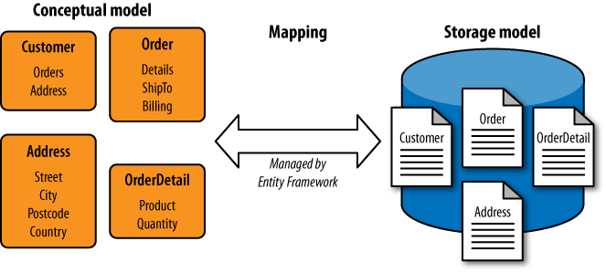
The design of a database doesn’t always correspond directly to data structures convenient for our application code. There are many reasons we might want our code to work with a model that looks slightly different from the data. The database may contain information not required by the part of the application we’re writing, so we may need only a subset. Information about a particular entity may have been split across multiple tables for performance reasons. Naming conventions in the database might not suit our code.
So the Entity Framework allows us to control the mapping. We can define a conceptual model that describes the entities as we’d like to work with them from C#, along with mappings that describe how that model maps onto the underlying storage. The EF also requires us to provide a store schema, which is a definition of the structure we expect it to find in the database. This may seem redundant—after all, the database knows its own schema, so why would the EF need a copy? There are a couple of reasons. First, it’s possible to define the model before you create the database—you can generate a database schema from the store schema. Second, you can configure aspects of how the Entity Framework uses the database, such as whether it uses queries or stored procedures to access particular tables. Settings that are associated with the database itself rather than what the EF does with data belong in the store schema rather than the mappings or conceptual schema.
The three parts shown in Figure 14-1—the conceptual model, the storage model, and the mappings between them—are collectively known as the Entity Data Model, or EDM.
Warning
There are many constraints on the conceptual model, because the model is useful only if you can construct a successful mapping. There are limits on what mappings are able to do, so your existing database structure will impose some restrictions on the model. Developers who are new to the Entity Framework often find that they have a lot less freedom in the design of the conceptual model than they first presumed. We’ll see what mappings are possible in due course, but for now, do not imagine that the EF is able to take any arbitrary conceptual model and bridge it to any old database structure—there is necessarily a close relationship between the database and the conceptual model.
If you use the EF in the simplest way possible, your conceptual model will be the same as your storage model, and the mapping will be very straightforward. If you use Visual Studio’s wizard for adding EF support to a project, you’ll end up with exactly this sort of direct mapping, with one entity type for each table or view you import. But you can then tweak things to suit your needs. We’ll walk through the wizard now—even though it produces a straightforward mapping where the conceptual model matches the storage model, it still has to generate a complete set of model and mapping definitions, so it’s instructive to look at what it produces.
You can add EF support to any .NET project (except for Silverlight projects). We’ll use a console application for the examples. In the Add New Item dialog, we’ll select Visual C# Items→Data, and then choose the ADO.NET Entity Data Model item template, calling the new file “AdventureWorksModel”.
When you add an Entity Data Model to your project, Visual Studio asks whether you want to start from scratch or base your model on an existing database. We’ll choose that simpler second option. If you’ve previously told Visual Studio about any databases you’re using—either via the Server Explorer toolbar or by using this or other data-related wizards—it will show them in a drop down, but you can provide Visual Studio with new connection details from within the wizard. For this walkthrough, we’re going to connect to the AdventureWorksLT2008 sample database.
Note
The wizard uses the name of your connection for one of the types
that it generates. You’ll see the identifier AdventureWorksLT2008Entities cropping up in
various examples later. If you happen to give your connection a
different name in Visual Studio, you’ll need to use that name in the
code.
Once you’ve chosen a database, Visual Studio will show a tree view
of all the tables, views, and stored procedures—you can use these as the
starting point for your model. For each item you select, it will add
corresponding items to the store schema, the conceptual schema, and the
mappings. When you complete the wizard, it will generate an .edmx file that defines the generated entity
model. Visual Studio opens a graphical view of this file—Figure 14-2 shows the conceptual
model that appears if you select the Customer, SalesOrderHeader, and SalesOrderDetail tables in the wizard and then
click Finish.
This view shows only the conceptual model. You can see slightly more
of the EDM in the Model Browser, shown in Figure 14-3. This will normally appear by
default when you open an EDM, but if you rearrange your windows and lose
track of it, you can right-click on the background of the model and choose
Model Browser from the context menu.
The browser lists both the conceptual schema (under the AdventureWorksLT2008Model
node here) and the store schema (under AdventureWorksLT2008Model.Store). The three
selected tables are visible in both, and if you were to expand them, you’d
see that the properties of each entity in the conceptual model correspond
directly to the columns of the tables in the store schema.
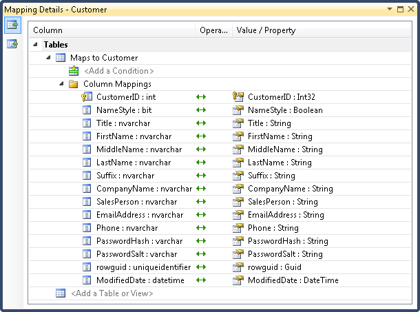
Even the Model Browser doesn’t show the complete picture, as the Entity Data Model has three parts: the conceptual schema, the store schema, and the mappings. To see the mappings, you can select either entities or properties of entities. When you do this in either the main .edmx editor view (Figure 14-2) or the Model Browser (Figure 14-3), the Mapping Details window, shown in Figure 14-4, will display the mappings for the selected item. The Mapping Details panel should appear automatically, but if you don’t see it, you can open it with the View→Other Windows→Entity Data Model Mapping Details menu item.
As Figure 14-4 shows, the
generated mapping is pretty simple. On the left you can see each column
from the table definition in the store schema, and on the right you can
see which entity property it is mapped to. Since the store schema and
conceptual model were generated directly from the database schema, there’s
nothing complicated going on—the same names appear on either side, and the
only difference is that the lefthand side shows data types from the
database world such as nvarchar and
bit, while the righthand side shows
.NET data types such as String and
Boolean.

Visual Studio puts the whole Entity Data Model definition in an .edmx file, which is just XML. The wizards and editor windows we’ve seen so far are just convenient views into that XML. If you look directly at the XML in the .edmx, you’ll see it contains sections corresponding to the three parts of the model—storage schema, conceptual schema, and mappings. But the whole point of this exercise was to make it easier to use data from code. So Visual Studio generates code based on the contents of any .edmx files in your project.
For each entity type you define, a corresponding .NET class will be generated. These classes provide normal properties for each property in the entity type’s definition. So when you create and edit entity types, you are in effect defining .NET types that you can use from your C# code.

Note
The generated types derive from EntityObject, a base class that enables the
object to participate in the Entity Framework. This includes features
such as change tracking so that the framework can know when it needs
to write updates to the database. The first version of the EF required
entities to derive from this base class or to implement certain EF
interfaces, but .NET 4 introduced so-called POCO (Plain Old CLR Object)
support, which makes it possible to use an existing class hierarchy
with the Entity Framework without having to modify those classes (as
long as you can create a successful mapping). There’s more work to do
that way—if you don’t derive from EntityObject you need to write extra
supporting code to provide the EF with enough information to know how
it should handle change tracking, identity, and relationships for your
objects. Here we’re sticking with the simpler approach of letting the
wizard generate classes that derive from the EF’s base type.
Visual Studio also generates one extra class representing
something called the object context. You use this to
obtain entity objects representing data already in the database and it’s
also where you go to add new data. And as we’ll see later, this object
provides other services for managing the data access operations. This
type derives from ObjectContext, and sometimes it’s just
referred to as the context. Example 14-3 uses this generated context
type to retrieve rows from the SalesOrderHeader table for a particular
date.
Example 14-3. Using generated entity types
using (var dbContext = new AdventureWorksLT2008Entities()) { DateTime orderDate = new DateTime(2004, 6, 1); var orders = from order indbContext.SalesOrderHeaderswhere order.OrderDate == orderDate select order; foreach (SalesOrderHeader orderin orders) { Console.WriteLine(order.TotalDue); } }
Notice that this example wraps the context in a using statement—the object context is a
disposable resource because it does a lot of work behind the scenes, and
it needs to tidy up once you no longer need the state it builds up. So
it’s important that you dispose it when you’re done with it.
The object context’s type here is AdventureWorksLT2008Entities. By default,
Visual Studio will just append the word Entities to
your database connection name. You can change this by selecting the
EntityContainer item in the Model
Browser—you can see this in the middle of Figure 14-3—and then use the Properties panel
to choose its name. But we’ll keep the default name in the
examples.
Notice that the LINQ query in Example 14-3 uses the context’s SalesOrderHeaders property as the query
source. That’s not quite the same as the table name—the wizard has added
an s. By default, the Entity Framework wizard will
attempt to pluralize and depluralize words as appropriate—in general, it
gives entity types singular names while properties that return
collections of entities are plural. (The names in our conceptual model
can differ slightly from our storage model thanks to the Entity Data
Model’s mapping.) If you don’t like this plural handling, there’s a
checkbox to turn it off when you import tables with the wizard.
Example 14-3 also uses the
SalesOrderHeader class generated for
the entity type of the same name. The order range variable in the LINQ query is of
this type, as is the order iteration
variable in the loop.
It’s this generated entity class that enables us to refer to
database columns using normal C# syntax. The LINQ query’s where clause uses that entity class’s OrderDate property to build a query that uses
the OrderDate column of the
corresponding database table. Likewise, the loop uses normal C# property
syntax to retrieve TotalDue, which
represents the column of the same name in the database.
If this seems rather uneventful, well, that’s the idea. Compare this to the much more fiddly code in Example 14-1—by mapping database columns to properties, the Entity Framework reduces the amount of friction involved in writing data access code.
Note
You can find the generated source code for the entities in the
Solution Explorer by expanding the .edmx file—you’ll find a file with a
similar name, but with .Designer.cs in place of .edmx (so AdventureWorks.Designer.cs in this case).
As with all generated code you should avoid modifying
it—Visual Studio tends to regenerate code from scratch each time any
setting changes. But if you’d like to add features to these generated
classes, that’s easily done—all the classes are generated with the
partial keyword, meaning that you can
put additional members in separate source files. You can add another
class definition with the same name as an entity type, marked with the
partial keyword, to any source
file. The C# compiler will effectively merge your partial class with
the generated partial class.
Let’s change things a bit, so the mapping has something to
do. Most of the column names in this example database happen to fit the
usual .NET conventions for property names, but there’s an exception: the
rowguid column in SalesOrderHeader is not capitalized in the
usual way. (This column exists to support SQL Server replication, so
it’s fairly unusual to want to use it from code, but in this example
it’s the only column with a funny-looking name.) If you change this name
to RowGuid in the designer (either by
double-clicking on the property or by using the Properties panel) Visual
Studio will update the mapping, and the Mapping Details panel will show
that the rowguid column in the table
is mapped to the RowGuid property of
the entity. (If you’d prefer a less subtle change, you could rename the
Customer entity’s ModifiedDate to, say, LastChanged. The mapping lets you use any
names you like.)
Changing the names of a few columns isn’t very exciting. (And with this particular example database it’s not even very useful, although if you’re dealing with more idiosyncratic naming schemes, renaming becomes more important.) So let’s look at one of the more interesting mapping features: the way in which the EF handles relationships between entities.
Databases usually have relationships between tables. In
the Adventure Works example, the Customer table has a foreign key relationship
with the SalesOrderHeader table. Both
tables have a CustomerID column. This
is the primary key of the Customer
table, and the database schema includes a constraint enforcing that the
CustomerID column in the SalesOrderHeader can contain only a value for
which a corresponding Customer row
exists. Or to put it more simply, each SalesOrderHeader row must be related to a
specific Customer row.
Note
This has nothing to do with the relations in a relational database, incidentally. The relational name comes from the set theory underpinning databases, and a relation is not the same thing as a relationship here. A relation effectively corresponds to a table.
Visual Studio’s EDM wizard looks for foreign key constraints in the database schema to discover the relationships between tables. In the EDM, it turns these into associations. (The distinction between a relationship and an association is somewhat subtle. An association is a named item in the Entity Data Model representing a particular relationship. The main reason this distinction exists is that relationships are a slightly more general concept—associations are capable of modeling only certain kinds of relationships.) Just as tables added with the wizard end up appearing in all three parts of the EDM—a table will appear in the store schema, a corresponding entity will be added to the conceptual schema, and there will be a mapping between the two—a similar process occurs for associations. If a foreign key constraint indicates that there’s a relationship between two database tables added through the wizard, Visual Studio will add an association to the EDM’s store schema and also to the conceptual schema, and it will set up a suitable mapping between these two associations. And on top of this, it will add navigation properties to the related entities in the conceptual model.
Note
In previous versions of the Entity Framework, foreign key
columns represented with navigation properties would not get scalar
properties providing direct access to the key values—there would have
been no CustomerID property on the SalesOrderHeader type, for example. This
proved awkward in practice, so starting with .NET 4 relationships are
represented both as the underlying foreign key value and also as a
navigation property.
Associations represent relationships between entities,
and the most natural way to present them in the world of objects is
through properties. For example, you’d expect an object representing a
sales order to provide a property that refers to the related customer.
That’s exactly what the EF does, and it also works in reverse: the
customer object provides a property that holds a collection of
references to all the customer’s orders. Example 14-4 shows a LINQ query that gets
the number of SalesOrderHeader rows
associated with each customer. It fetches one property from the
Customer entity class that maps to
a column in the database (CustomerID) and also uses a property called
SalesOrderHeader, which represents
the customer’s orders.
Example 14-4. Using a navigation property
using (var dbContext = new AdventureWorksLT2008Entities())
{
    var customerOrderCounts = from cust in dbContext.Customers
                              select new
                              {
                                  cust.CustomerID,
                                  OrderCount = cust.SalesOrderHeaders.Count
                              };
    foreach (var customerInfo in customerOrderCounts)
    {
        Console.WriteLine("Customer {0} has {1} orders",
            customerInfo.CustomerID, customerInfo.OrderCount);
    }
}
The database table that the Customer entity class represents does not
have a column called SalesOrderHeader. The Entity Framework
wizard added this property to represent the relationship between the
Customer and SalesOrderHeader tables. This is not an
ordinary property—in Figure 14-2 you can see that it
appears separately, under Navigation Properties.
From C# code, a navigation property looks like a collection.
Example 14-4 just retrieves the
Count property, but we could do
more advanced things. The query in Example 14-5 has a nested
query for each customer that looks for all shipped orders (those with
a Status of 5), and for each one it reads the total due
for that order and a count of all the SalesOrderDetails rows associated with that
order. So this uses two navigation properties—the one representing the
relationship between customers and orders, and the one representing
the relationship between orders and order details.
Example 14-5. Traversing multiple relationships with navigation properties
var info = from cust in dbContext.Customers
           select new
           {
               cust.CustomerID,
               Orders = from order in cust.SalesOrderHeaders
                        where order.Status == 5
                        select new
                        {
                            order.TotalDue,
                            ItemCount = order.SalesOrderDetails.Count
                        }
           };
There’s a reason we’ve used LINQ in these last two examples—it
happens to avoid an issue with navigation properties. How does the EF
decide how many entities to load for us, and when? In Example 14-4, the LINQ query just
retrieves two pieces of information for each customer—the CustomerID and the order count—and while
Example 14-5 is more
complex, it’s still circumscribed, so the EF can inspect the query to
work out exactly what it needs to retrieve. But when we’re not using
LINQ, how does the EF know what to do? For instance, consider the code
in Example 14-6.
Example 14-6. Following an association after the initial query
Customer myCustomer = dbContext.Customers.Single(
    cust => cust.CustomerID == 29531);
Console.WriteLine(myCustomer.SalesOrderHeaders.Count);
This fetches the entity for a specific customer, and then tries
to get the number of SalesOrderHeader entities to which this item
is related. Prior to .NET 4, this did not work—it would print out
0, even though the example database
has one related order for this customer. In .NET 3.5 SP1, the Entity
Framework would initialize navigation properties such as the Customer object’s SalesOrderHeaders property with an empty
collection, and would load the related objects only if we ask it to,
using the Load method shown in
Example 14-7.
Example 14-7. Explicitly loading entities for an association
Customer myCustomer = dbContext.Customers.Single(
    cust => cust.CustomerID == 29531);
myCustomer.SalesOrderHeaders.Load();
Console.WriteLine(myCustomer.SalesOrderHeaders.Count);
.NET 4 adds an alternative way to do this, called lazy loading. Rather than having to
call Load explicitly, the EF can
automatically load related objects at the point at which you access
them. The context has a property to control this:
dbContext.ContextOptions.LazyLoadingEnabled = false;
This is true by default;
setting it to false reverts to the
pre-.NET 4 behavior. With this option switched on, Example 14-6 is equivalent to
Example 14-7, because
the EF will call Load for us when
we first try to use the navigation property. (The collection ignores
calls to Load if the entities are
already loaded, so requesting multiple loads is not a problem.)
In either case, the EF has to make an extra trip to the
database. The call to Single will
fetch the customer from the database before returning, which means
that a second request is required when we later ask it (either
explicitly or implicitly) to fetch the related rows, because the EF
didn’t know we were going to use these items until we asked for them.
This might not be a problem, but in general, the more trips you make
to the database, the slower things go.
Warning
Be wary of enabling lazy loading, because it can sometimes result in a lot of unnecessary database requests. For example, one author was involved with a project that had some diagnostic code that “helpfully” wrote a snapshot of certain objects into a log, including the value of all their properties. Unfortunately, this code was recursive—if a property referred to another object, it would display that too, and if a property referred to a collection of objects, it would show all of them. This logging code had cycle detection, so it wouldn’t get stuck in an infinite loop, but otherwise it wouldn’t stop until it had showed every object reachable from the starting point. Unfortunately, lazy loading was enabled, so when this code was given an entity, it ended up fetching all entities that were related, no matter how distantly, to the first object at hand, so it hammered the database with thousands of requests each time a log entry was generated.
Modern databases are surprisingly fast—it’s possible for this sort of problem to go unnoticed on development machines with their own local database instance. But you probably don’t want it happening on a busy live server.
To get consistent results you’d want to make sure the initial
query and subsequent lazy loads happen as part of a transaction (as
shown later), but to ensure scalability in a busy system you want to
minimize the number of requests made in any single transaction. So you
can tell the EF that you want certain related entities to be fetched
at the same time as the main result. You do this with the Include method shown
in Example 14-8, which is
available on any of the entity sets provided by the context.
Example 14-8. Specifying relationships to preload
var customersWithOrderDetails = dbContext.Customers.
    Include("SalesOrderHeaders.SalesOrderDetails");
Customer myCustomer = customersWithOrderDetails.Single(
    cust => cust.CustomerID == 29531);
Console.WriteLine(myCustomer.SalesOrderHeaders.Count);
This call to Include asks to
load related entities available through the Customer entity’s SalesOrderHeaders property. (These will be
loaded regardless of the lazy loading setting.) It also says that for
each of those related entities, the EF should load any related
entities visible through the SalesOrderDetails property. In other words,
this tells the EF that we would like it to fetch all of the orders for
this customer and all of the details for those orders. It will
generate a single query that fetches all of the necessary information
in one request.
Note
If you’re wondering why it doesn’t just prefetch all related items all of the time, consider the performance implications. In some circumstances, aggressively prefetching all related items might amount to attempting to copy a significant fraction of your database into memory! But even in more circumscribed cases, fetching more data than you need can slow your system down or reduce scalability.
So far we have seen only so-called one-to-many relationships—one customer can be related to many orders, one order can be related to many order details. But there are other kinds of relationships.
The multiplicity of a relationship refers to the number of participants at either end of the association. In the Entity Framework, an association’s multiplicity determines the nature of the navigation properties that represent the relationship.
Note
In the Entity Framework, there are always two ends to an association, regardless of the multiplicity. For example, we have customers at one end of a relationship and orders at the other end. The multiplicity describes how many items may be at a particular end, not how many ends there are.
You will sometimes want to represent more complex relationships—for example, a so-called ternary relationship involves three kinds of parties. This is a different concept from multiplicity and is called degree. For example, consider a teaching arrangement in a college, where a student is taught a subject by a teacher; this relationship involves three entities (student, subject, and teacher). These higher-degree relationships are typically modeled in the database by having a table just for the relationship itself. Likewise, the EDM does not directly support relationships with a degree of more than two, so you would represent such a relationship with a distinct entity type in the conceptual model, adding associations between that entity and all the participants in the relationship.
For each end of a relationship, you can specify a multiplicity
of either 1, 0..1, or *. The first, 1, means what it says—there is always one
item at that end of the association. The last, *, means any number—there can be zero, one,
or several items at that end. A multiplicity of 0..1 means zero or one—this indicates that
the association is optional, but where present, there is just one
entity at this end.
In a one-to-many relationship, the two
ends have a multiplicity of 1 and
*, respectively. You can see this
in Figure 14-2—the lines
between entities represent associations, and the multiplicity appears
at each end of the line. So an item at the first end can be related to
any number of items at the second end; an item at the second end is
always related to exactly one item at the first. In C#, the entity at
the 1 end would have a navigation
property that offers a collection, in order to provide access to the
many end. The entity at the * end would provide a simpler noncollection
property to get back to the one entity it is related to.
A variation on this theme has 0..1 instead of 1 at the first end, and * at the second end as before. This is
similar to a one-to-many relationship, except items at the
many end don’t necessarily have to be related to
an item at the other end. For example, you might want to represent the
relationship between managers and their reports. But if you go far
enough up the corporate hierarchy, you will find someone who has no
manager—the navigation property would return null. So a simple
one-to-many relationship doesn’t work here—you would need 0..1 instead of 1 at the manager end of
the association.
Sometimes one-to-one relationships crop up—each item at one end is always related to exactly one item at the other end. This is an unusual kind of relationship because it implies that entities are inextricably and exclusively linked. Relationships that sound like they might be one-to-one are often not. Here’s an illustration from popular culture, describing a relationship between a master and an apprentice expressed as: “Always two, there are. No more, no less. A master, and an apprentice.”[35] A master always has an apprentice, an apprentice always has a master, so isn’t that a one-to-one relationship? In fact, this might need to be a one-to-many relationship because on the death of an apprentice, the master takes a new apprentice. (The apprentice has just one master, as the only career paths are promotion to master or untimely death. So we can at least be sure that this is not a many-to-many relationship.) The constraint expressed here is merely that the master has a one-at-a-time approach to relationships, much like serial monogamy. (For example, both Darth Maul and Darth Vader were apprentices of Darth Sidious.) So if the database needs to reflect the full history rather than just the current state, a one-to-one relationship won’t be sufficient. (Although if you only need the database to store the current state, one-to-one might be fine here.) In databases, one-to-one relationships often exist because information about a single entity has been split across multiple tables, perhaps for performance reasons. (The EF lets you map this back to a single entity in the conceptual model, so such relationships are likely to be more common in the store schema than the conceptual schema.)
Variations on one-to-one where one or the other end is optional
can be useful.[36] For example, you might have an entity representing a
customer and an entity representing an account. An organization (such
as a butcher shop) might choose to have a policy where customers are
not required to have accounts, but where accounts are held any single
customer can have only one account, and accounts must be held by
exactly one customer. (That’s not the only imaginable policy, of
course.) The relationship between a customer entity and an account
entity would have a multiplicity of 1 at the customer end and 0..1 at the account end.
Finally, there are many-to-many relationships. For
example, you might have an entity type to represent a standard part
such as an M3 bolt, and an entity to represent a part manufacturer.
Many manufacturers are capable of producing M3 bolts, and most
manufacturers produce more than one kind of product. To model the
relationship of who produces what in the EDM, you could use an
association with a multiplicity of * for both ends of the association. And in
code, both entities would have navigation properties offering
collections of objects.
However, there’s an issue with many-to-many relationships in the EF. In the database, such a relationship is represented as a separate table, where each row contains two foreign keys, one for each end of the relationship. If that’s all the table contains, the EF will happily let you map this table to an association in the conceptual model, and the navigation properties will work as described. However, if the table contains other information, you will end up needing to represent it as an entity in its own right. For example, given the product/manufacturer example earlier, it might turn out to be useful to know what product code a particular supplier uses for a particular standard product. There’s no place for this information to go if you just have navigation properties on the product and manufacturer that point to one another—you would need an extra entity type to hold this property that is specific to a particular product/manufacturer combination.
This can get slightly awkward when there are columns in the relationship table that your application doesn’t particularly care about, but which the EF insists are mapped because they are nonnullable and don’t have default values. Your conceptual model would not be able to represent this table as a simple many-to-many association, because that would leave nowhere to map the relationship property. (The underlying issue here is the same one that prevents you from omitting certain database columns from your entities.)
Finally, we’ll look at one more feature of the Entity Framework’s mapping capabilities: support for inheritance.
Inheritance presents a challenge for an ORM, because the typical object-oriented notions of inheritance don’t have any direct parallel in the relational model. Various solutions exist because there isn’t one really good way to do this. The Entity Framework supports mappings for a couple of the popular approaches for attempting to bridge this chasm.
While there are several approaches to mapping (which we’ll get to shortly), the conceptual model’s handling of inheritance works the same way in all cases, and is very similar to inheritance in C#. Any entity type can optionally specify one other entity type as its base type. Entities with a base type inherit all the properties from that base. An entity cannot specify more than one base type, but you are allowed to derive from an entity that derives from another entity (i.e., you can have an inheritance chain). And the corresponding generated entity classes that you use from C# will represent these inheritance relationships with normal class inheritance.
You will need to define mappings for your base entity type in the usual way. All the derived types will inherit these mappings. The question is: how do we map features unique to individual derived types?
The first mapping approach involves mapping all entity types
sharing a particular base entity type to a single table in the database.
The entity type the EF chooses to represent a particular row is chosen
based on a discriminator column—in the mapping you
simply provide a list that says, for example, if the discriminator
column contains 1, the entity type is Employee, and if it’s 2, the type is Manager, while if it’s 3, the type is Director, and so on. These derived types will
presumably have additional properties distinguishing them from one
another, and these would map to nullable columns in the table. They will
need to be nullable, because these columns will have values only when
you’re using the derived types that support them—non-nullable database
columns need to be mapped to properties in the base entity type if
you’re using this mapping style.
The second mapping approach uses a separate table for each derived type. Derived types still inherit the base mappings, so in this scenario, derived entity types will be involved with two or more tables: the table unique to the derived type, along with any tables used by the base type. This approach requires all the tables involved to use the same primary key.
None of these mapping features would be much use without some way to retrieve data from the database, so we’ll now look at how to execute queries in the Entity Framework.
[35] Yoda discussing Sith terms of employment, from Star Wars Episode I: The Phantom Menace.
[36] Opinion is divided on whether this variant can still be called one-to-one. Strictly speaking it’s incorrect, but in practice you’ll see one-to-zero-or-one relationships widely described informally as one-to-one.