Narrow-Gauge Locomotives 1871–1971
In order to understand the overall contribution made to the historical and technical development of narrow-gauge locomotives by events at the Royal Arsenal, certain observations should be made relating to the state of affairs in this field that prevailed immediately prior to the first locomotive’s acquisition for use on the Arsenal’s railway system. Although much is rightly made of the importance of the early George England-built locomotives for the Ffestiniog Railway, it should be remembered that they were in no way the earliest narrow-gauge steam locomotives and that even by the 1840s Messrs Vulcan Foundry & Co. had supplied four 2ft 6in-gauge steam locomotives to the War Department for the purpose of hauling artillery. Sadly, the maker’s drawings of these locomotives do not survive, and their construction preceded both the dawn of railway photography and the widespread circulation of professional journals relating to engineering matters in general, let alone narrow-gauge locomotive design. All that is known of them is that they were completed in 1845 to two designs: Works Nos 213–4 were of the 0-4-0 wheel arrangement with 10in x 16in cylinders and 2ft 9in diameter coupled wheels, while Works Nos 215–6 were 0-4-2s with 11in x 18in cylinders and 3ft coupled wheels. As far as it is known, these were the first locomotives constructed in the United Kingdom specifically for military purposes, but it is not known how long they remained in use. What can be said with certainty, however, is that owing to the lack of publicity surrounding them, any useful lessons that could have been learned during their construction and from their subsequent operation were lost to the engineering world at large, a fact evidenced by some of the design proposals put forward in connection with the introduction of steam locomotives on the Ffestiniog Railway.
The period between 1845 and 1863 saw the appearance of a number of narrow-gauge designs, many for gauges of between 2ft 6in and standard, and these included such diverse examples as the 4ft-gauge inclined cylinder 0-4-0s for the Padarn Railway, a 3ft-gauge Neilson ‘Box Tank’ 0-4-0ST with only one (rear-mounted) cylinder, and a 2ft 8in-gauge 0-4-0ST design from Messrs Fletcher, Jennings & Co. of Whitehaven that was eventually developed into the first locomotive for the Talyllyn Railway. One problem for the future development of non-articulated narrow-gauge steam locomotives that was immediately apparent from examination of the design of the England 0-4-0 tank locomotives of the Ffestiniog Railway was that these locomotives’ firebox proportions precluded the use of full-length one-piece mainframes. Indeed, on these locomotives the drawbar loading was passed directly through the firebox wrapper, a situation that was only altered in more recent years on Prince by strengthening the footplate valences in order to relieve unwanted stresses. The first of the 18in-gauge locomotives for use at Crewe Works, 0-4-0ST Tiny, essentially reverted to much of the constructional layout used in the single-cylinder Neilson ‘Box Tank’, save for the use of two inside cylinders (mounted in the conventional position) and a simplified cylindrical firebox crosssection. With Tiny, therefore, a point of development had been reached where full-length inside mainframes were adopted at the expense of using a non-depending firebox with all its structural and steam-raising limitations.
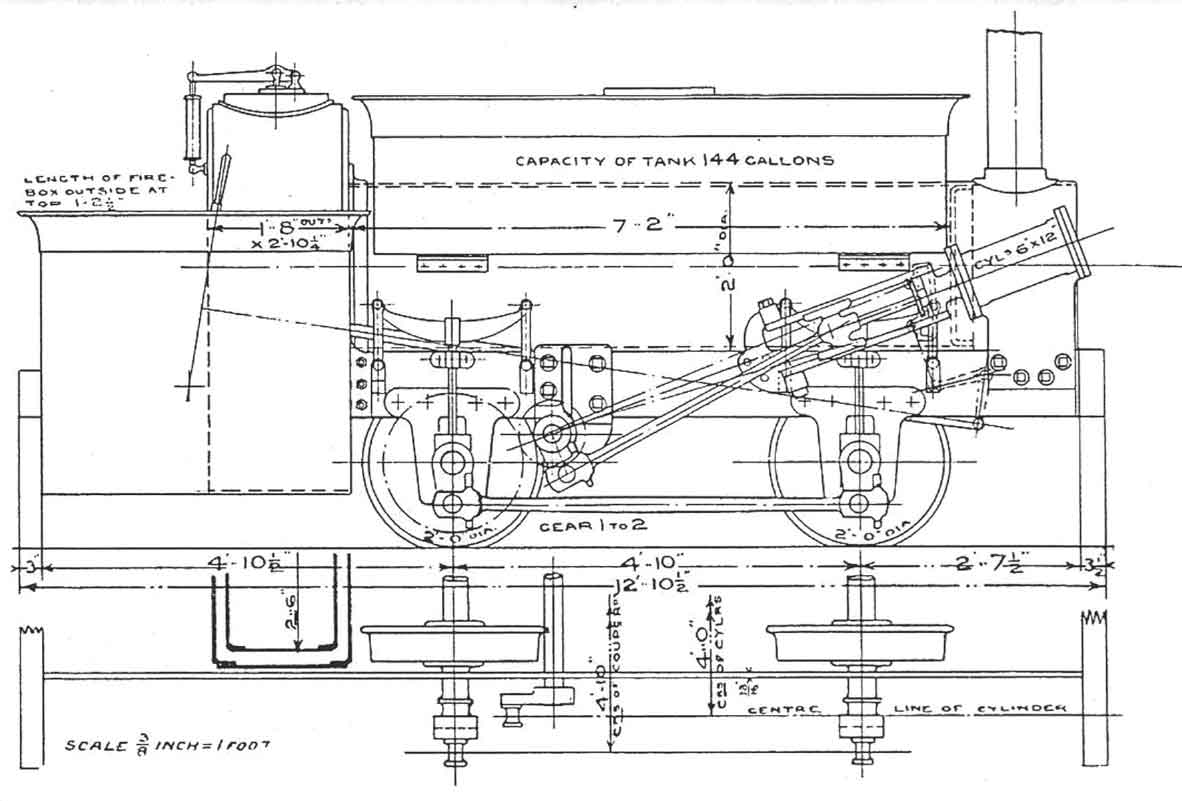
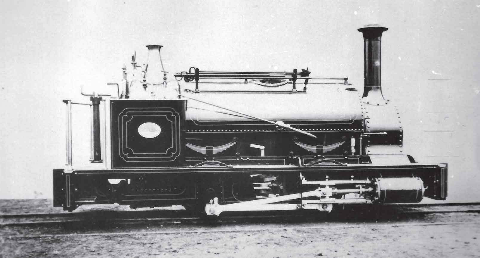
Tiny’s design was adopted in commercial form outside the railway workshop sphere on only two occasions: the 18.5in-gauge Works No. 2079 of 1870 Little Dorrit (shown in the accompanying drawing and photograph), and five years later in 1ft 10in-gauge form as the first locomotive on the Guinness Brewery Tramway in Dublin. However, a modified 2-2-0ST version, built for the Copiapo Mining Co. in Chile by Black, Hawthorn & Co. in 1887 to 1ft 8.5in gauge survives today (presumably width restrictions precluded the fitting of coupling rods), as do replicas of the Great Laxey Lead Mining Co. 1ft 7in 0-4-0Ts Ant and Bee, a much-modified ‘derivative’ design. The specification was adapted by Francis Webb at Crewe to produce a design of locomotive (initially powered by a Brotherhood three-cylinder motor, but later by two conventional cylinders fitted with footplate-controllable slip eccentric valve gear) with driving footplates and equal overhangs at both ends. This design even appeared at the Arsenal in 1878 (Fox Walker Works No. 386) as we saw in Chapter Two. Beyer Peacock & Co. Ltd went on to produce the most successful of the ‘railway workshop’ 18in designs: a 0-4-0WT with conventional cylinders and valve gear, inside frames, cylindrical firebox and unequal overhangs that was adopted (eventually in saddle tank form) by the Lancashire & Yorkshire Railway at Horwich. Today, two locomotives of this design survive: the Beyer Peacock works locomotive Dot (No. 2817 of 1887) in virtually ‘as built’ condition, and the ex-L&YR Wren (No. 2823 of 1887) which is preserved in modified form as a saddle tank.
Although the inside-framed locomotive with a nondepending firebox was eventually adapted by W.G. Bagnall & Co. of Stafford into the ubiquitous ‘Bullhead’ boiler 0-4-0ST locomotives familiar today, this locomotive dynasty offered only limited opportunities for development into larger designs. The earliest reliably documented movements in a totally different direction for sub-2ft 6in-gauge locomotive design were made by Isaac Watt Boulton of Ashton-under-Lyne in 1861–4. Boulton produced two 2ft-gauge 0-4-0STs with geared transmission and full-length outside mainframes allowing for a proper locomotive pattern firebox of reasonably generous proportions. The use of gearing was not widely adopted and Boulton did not go on to turn his initial efforts into a coherent strategy for marketing direct drive variants of these locomotives, but they were considered of sufficient merit to warrant mention in Engineering’s discussion of Tiny in 1866. In the end, it was left to two neighbouring Leeds companies to establish a line of locomotive development that was to have a major impact on the course of narrow-gauge railway history worldwide. In 1870, Hunslet Engine Co. turned out a 0-4-0ST locomotive Dinorwic for use on the village tramway line associated with the Dinorwic slate quarries in North Wales. The engine, Works No. 51, possessed full-length outside frames, outside cylinders, a locomotive-type boiler and direct drive and its features were noted in The Engineer soon after construction. The locomotive, as was to be expected, was well-made and equipped with many of the features associated with its wider-gauge brethren. From the point of view of the wider adoption of its constructional principles, it was handicapped by its overall size (including 9in x 14in cylinders and a 4ft 3in wheelbase) and by the fact that the horizontally-mounted cylinders and steamchests were prone to damage from obstructions, especially the steamchest-mounted cylinder drain cocks. As a consequence of these observations, Dinorwic’s design was duplicated only once, as George (Works No. 177 of 1877) for the same customer. For this reason, it can be stated that although Hunslet had struck the crucial technical blow, there still remained the commercial hurdle of producing a locomotive that was sufficiently compact to satisfy the requirements of many potential industrial customers. Nonetheless, Dinorwic and George were relatively long-lived, lasting until 1936 and into the Second World War respectively, although both were out of use for long periods at the end of their careers.

This drawing shows the locomotive supplied by Isaac Watt Boulton in 1861 for use on a 2ft-gauge line at Cross, Gidlow and Swanling Colliery, Wigan. This engine was allegedly a rebuild of a standard-gauge machine of 1856. The use of full-length outside mainframes directly attached to both bufferbeams is readily apparent. (The Locomotive)
The accompanying drawing shows Lilliputian, another I.W. Boulton product, built in 1864 as a development of the previous 2ft-gauge locomotive. The gauge, geared transmission and full-length outside mainframes were common to both locomotives. (The Locomotive)
The final piece of the jigsaw – the adaptation of the basic arrangement of Dinorwic to a design that would inspire universal adoption of its principles – fell to Manning Wardle & Co. Ltd and the early experiences with 0-4-0ST Works No. 353 of 1871, later named Lord Raglan, have already been mentioned. The locomotive was a ‘special’ constructed to a specification laid down by the Arsenal and attracted much attention from the engineering press of the time. It had inclined cylinders of 6in diameter with 8in stroke, wheels of 1ft 8in diameter set at a wheelbase of 3ft 3in, most suitable for running on the Woolwich minimum radius of 25 feet, and its cylinders, unlike those of Dinorwic, were inclined at a tangent of 3/26. The design was the world’s first series-produced sub-2ft 6in-gauge-class locomotive to combine full-length outside frames, outside cylinders, direct drive and a proper locomotive boiler. The fitting of an ornate canopy and water feed pump (to back up the injector) were characteristic of many of the company’s products. It is not certain when the dual-gauge bufferbeams and drawhooks initially fitted to Lord Raglan were removed and the mainframes modified, but it may be that this was done in two stages, with the original bufferbeams and upper frame extensions going by January 1873 and mainframe modification occurring at a later date.
In 1873 the next two Manning Wardles arrived, Victoria, Works No. 477, and Albert Edward, Works No. 482. The former of these two locomotives established the true Woolwich variant of the Manning Wardle 6 x 8 narrow-gauge 0-4-0ST that incorporated the modifications of a footplate with a long dropped portion, chamfered mainframes, full-width single composite iron and timber buffers and combined bevel-geared handbrake and reverser pedestals attached to the firebox wrapper. In all a further ten locomotives built by Manning Wardle to similar specification were supplied to the Arsenal up until 1889. The maker’s details relating to all class members as supplied are reproduced in Appendix VII, while the name changes resulting from the 1891 unification of the Arsenal’s railway system are shown in Appendix IX. Arquebus (Works No. 1130 of 1889) was the last of the thirteen, and Manning’s Engine Book records that Arquebus was a ‘special’. Although generally similar to No. 612 of 1876, variations included a special canopy with weather screens back and front, Beck’s patent whistle fitted on top of the canopy, a brass chimney cap, no handrail on the saddle tank and a spark arrester in the smokebox. As can be seen from Appendix VII, from Works No. 555 onwards, the makers recorded the specific department of the Arsenal to which each engine was supplied. During the 1870s and early 1880s, the Manning Wardle locomotives were the mainstay of operations all over the 18in-gauge system, and a photograph published in The Navy and Army Illustrated in 1899 and reproduced here even shows Arquebus on a specially-posed passenger working. By this stage, however, as was recorded a year earlier in Narrow Gauge Railways – Two Feet and Under, the arrival of larger and more powerful locomotives had resulted in the class largely being confined to operation within the tight limits of the shop areas, although their usefulness was far from over. Although the date of their phasing out by the makers on the Woolwich-pattern 18in-gauge Manning Wardle locomotives cannot be ascertained from surviving records, it is known that the earlier class members were fitted with a feedwater preheater (supplied with steam taken from the firebox wrapper steam space). This clearly indicates that the injector was originally intended as a back-up feature for use when the locomotive was stationary, with reliance being placed upon the feedpump when the locomotive was in motion. With the increasing reliability of injectors from the mid-1870s and the superseding of the early Giffard pattern, it was felt by the makers that customers would make more use of the injector while the locomotive was in motion, hence the preheater pipes were soon dispensed with. As will be seen later, the last standard-gauge Manning Wardle supplied to the Arsenal with a Giffard injector was built in 1878 as Works No. 676, although photographic evidence and the lack of reference to the matter in the maker’s records until locomotive No. 986 suggests that the Giffard injector was used for the 18in-gauge locomotives up to and including No. 939.
Enter the Leeds influence: following on from the successful production of specialized small standard-gauge tank locomotives for use by contractors and collieries by the Leeds manufacturer E.B. Wilson & Co. during the 1850s and the company’s demise in 1858, similar locomotives were built initially by Manning Wardle, joined shortly afterwards by Hunslet Engine Co. and Hudswell Clarke. The common thread running through most of these designs was the classic ‘Leeds pattern’ domeless boiler with raised firebox wrapper which appeared in rough sketch form in David Joy’s diaries and on Wilson products from around 1850 onwards. Another common feature in use by the early 1860s was the provision of one feedpump and one injector. The standard-gauge locomotives were, of course, fitted with inside mainframes. Following on from Manning Wardle’s unsuccessful tender for the contract to build the Ffestiniog Railway’s first locomotives and this company resorting to the use of non-continuous mainframes for the Ffestiniog & Blaenau Railway’s 2ft-gauge 0-4-2STs in 1868 (in order to obtain a decent size firebox), rival concern Hunslet Engine Co. adopted another approach in the production of its first sub-2ft 6in-gauge locomotive. This works photograph shows the right-hand side of Hunslet Engine Co. Works No. 51 of 1870 Dinorwic, the 1ft 10.75in-gauge 0-4-0ST supplied for use on the Dinorwic slate quarries’ ‘Village Tramway’. The Leeds pattern boiler was very much in evidence, albeit allied to a semi-circular profile water tank, which was used rather less often on early Manning Wardle and Hunslet locomotives than the flat-sided pattern. The combination of an axle-driven feedpump and a single injector, customary on the maker’s standard-gauge 0-4-0STs of the period, was also present, as were the outside cylinders although these were horizontal rather than inclined. In order to accommodate the relatively wide firebox wrapper, it was decided to revert to the full-length outside frames of the Boulton locomotives, but this time of more substantial construction and fitted to a locomotive utilizing direct drive rather than gearing. Despite a respectable working life of over forty-five years (much of which was spent within the quarries themselves after the engine had been displaced from the Village Tramway), Dinorwic’s design was duplicated only once. Although, as mentioned in the text, the slim-gauge locomotive had finally ‘grown up’, Dinorwic’s design effectively fell between two stools when assessed against customer requirements of the early 1870s, lacking the low axle loading of the specialist long wheelbase ‘Fell’ types, or the compactness (particularly of wheelbase) required for many quarry and factory applications where tight curves abounded. (Maker’s photograph)
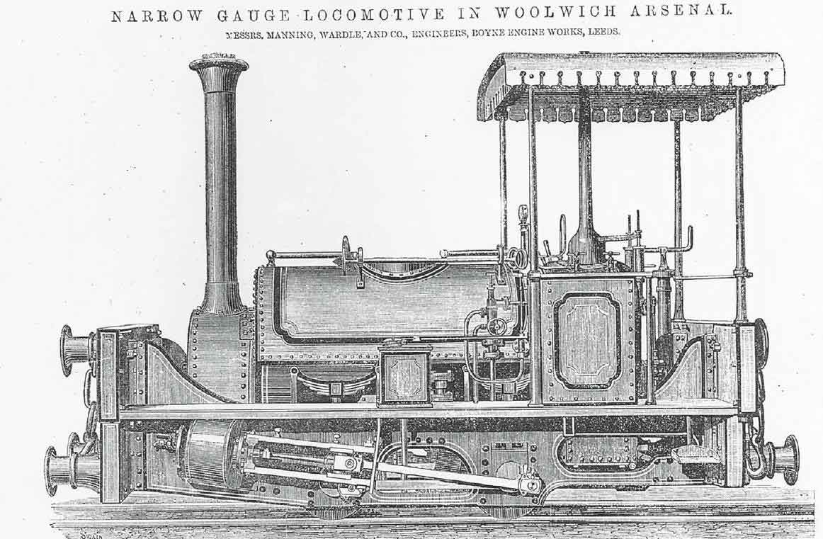
Lord Raglan, the first railway locomotive supplied to the Royal Arsenal, is illustrated in this engraving. As mentioned in the text, the engine was the maker’s Works No. 353 of 1871 and it remained in use on the Royal Arsenal Railways system until withdrawn from service and scrapped during the First World War. The maker’s records indicate that the engine’s mainframes were modified at the Arsenal to be standard with the pattern used by its subsequent classmates but it is difficult to see how this could have been accomplished without renewing the side mainframes. The trial run of this locomotive, at Boyne Engine Works in the presence of the Arsenal’s assistant inspector of machinery, Lt. Heneage, was recorded in the ‘Leeds Mercury’ for February 25th 1871. (The Engineer)
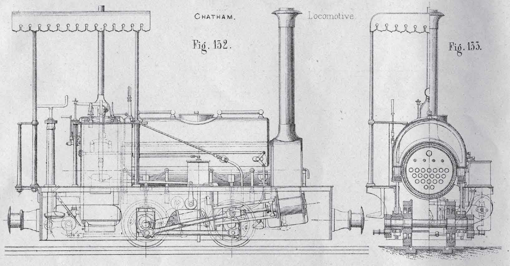
The article featuring Lord Raglan in Engineering appeared in 1873 (some time after the engine was featured in The Engineer), and although it used the same source engraving for the side view, the main body of the text concentrated on the fact that the three Manning Wardle products using similar working components that had been completed in the meantime had all been supplied to Chatham. Works Nos 386 of 1871 Trafalgar and 424 of 1872 Busy Bee were constructed for use in the dockyard, while 448 of 1873 Burgoyne was supplied (shortly before the appearance of the article) to the School of Military Engineering. No General Arrangement was ever known to have been produced for Lord Raglan (or, for that matter, Trafalgar), hence Engineering turned to the GA for Busy Bee for inspiration when incorporating a drawing of the type into the feature. This was in turn copied by Vignes, even to the extent of the omission of the rear edge of the angle iron securing the left-hand mainframe to the leading bufferbeam (a mistake originally made in Engineering)! Owing to the ‘Chatham bias’ of the Engineering feature, Vignes appears to have mistakenly assumed that the rectangular ‘short-framed’ variant of the specification (pioneered with Busy Bee and adopted for five of its dockyard sisters plus Burgoyne) was the sole mature form, hence ignoring the ‘Woolwich’ specification that was to appear shortly after the publication of the Engineering feature. (Vignes Etude)

The rear view shows the upper backhead detail and the ornamental canopy more closely associated with the maker’s products for the export market. The other feature most immediately apparent is the unsightly ‘double’ bufferbeam used to enable the engine to handle standard-gauge wagons. (The Engineer)
The impact of the acceptance by the railway engineering world in general of the Manning Wardle 6 x 8 0-4-0STs cannot be overstated. The class was featured in both The Engineer and Engineering (in 1871 and 1873 respectively), it was also featured in the influential Vignes Etude of 1878 and in 1873 a Chatham-pattern class member was purchased for evaluation by the Royal Engineers at Chatham’s School of Military Engineering, partly on the grounds of the type’s anticipated widespread adoption. In addition to its basic specification being adapted (in long wheelbase form) by the makers for use on locomotives of a type promoted by John Barraclough Fell, both at home and for export, its most immediate impact was on the evolution, from 1879 onwards, of the mainstream ‘Quarry Hunslets’ and their close relatives. Soon the direct drive, full-length outside frame, outside cylinder, locomotive pattern boiler combination was being adopted for locomotives of 2ft 6in gauge and under by many builders, both inside and outside the City of Leeds, and would remain the order of the day until the end of steam locomotive construction for the 18in-gauge system at the Royal Arsenal. Apart from the Quarry Hunslets, celebrated British-built examples of the basic genre included Beddegelert of the North Wales Narrow Gauge Railway; Russell of the Portmadoc, Beddegelert & South Snowdon; the Lynton & Barnstaple and Vale of Rheidol 2-6-2T classes; the Leek & Manifold 2-6-4Ts; all except the first of the Campbeltown & Machrihanish locomotives; and many examples for non-passenger lines such as Jack and Mary for the Cliffe Hill Granite Co. Narrow-gauge locomotives of this basic type were also constructed by overseas builders in places as diverse as France, Germany, Australia and, in bar-framed form, the USA. In its home country, the last locomotive of the basic type constructed for non-tourist use was Hunslet Works No. 3902 of 1971, an updated version of the Kerr, Stuart Brazil-class 0-4-2ST for export to Indonesia. This historic locomotive has since been returned to the United Kingdom for preservation and is now resident at Statfold Barn near Tamworth, Staffs.
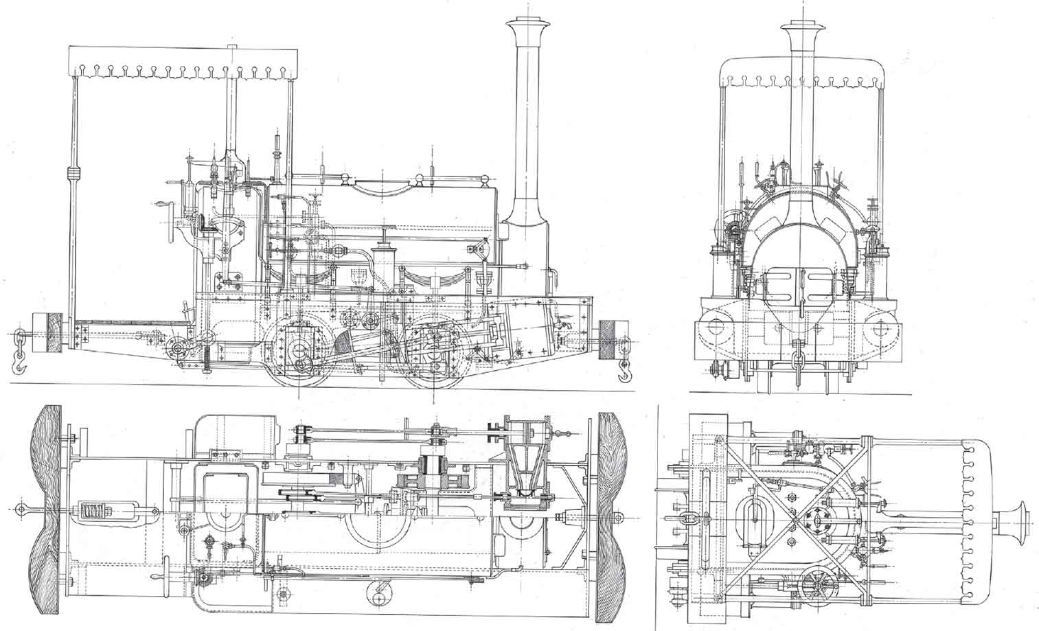
The early mature form of the ‘Woolwich’ specification of Manning Wardle 6in x 8in 0-4-0ST appeared as Works No. 477 Victoria in November 1873 and, as with Busy Bee for Chatham Dockyard, a General Arrangement was prepared. At this stage of development, the fully-fringed canopy is still evident, as is the open footplate with wooden flooring, the exposed bevel-geared brake control/reverser assembly and pipework for the pressure gauge, tank preheater, blower and feedpump (both starting and main water pipes) found on parts of the Arsenal’s railway system are very much in evidence. A Giffard injector would have been fitted on the left hand side and this is shown in dotted outlines. Victoria was renamed Boxer, presumably in 1901, was rebuilt within the Arsenal in 1911 and remained in RAR service until 1916. (The late R. Smithers)
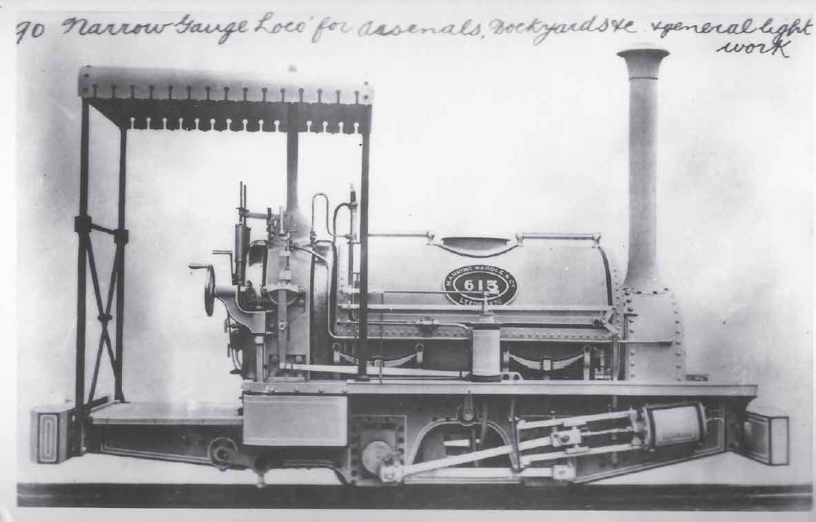
The early mature 18in-gauge Manning Wardle specification is exemplified by this works’ photograph of No. 613 of 1876. As with Lord Raglan, the nameplate is not shown, but the locomotive was named Shrapnel. (Maker’s photograph)
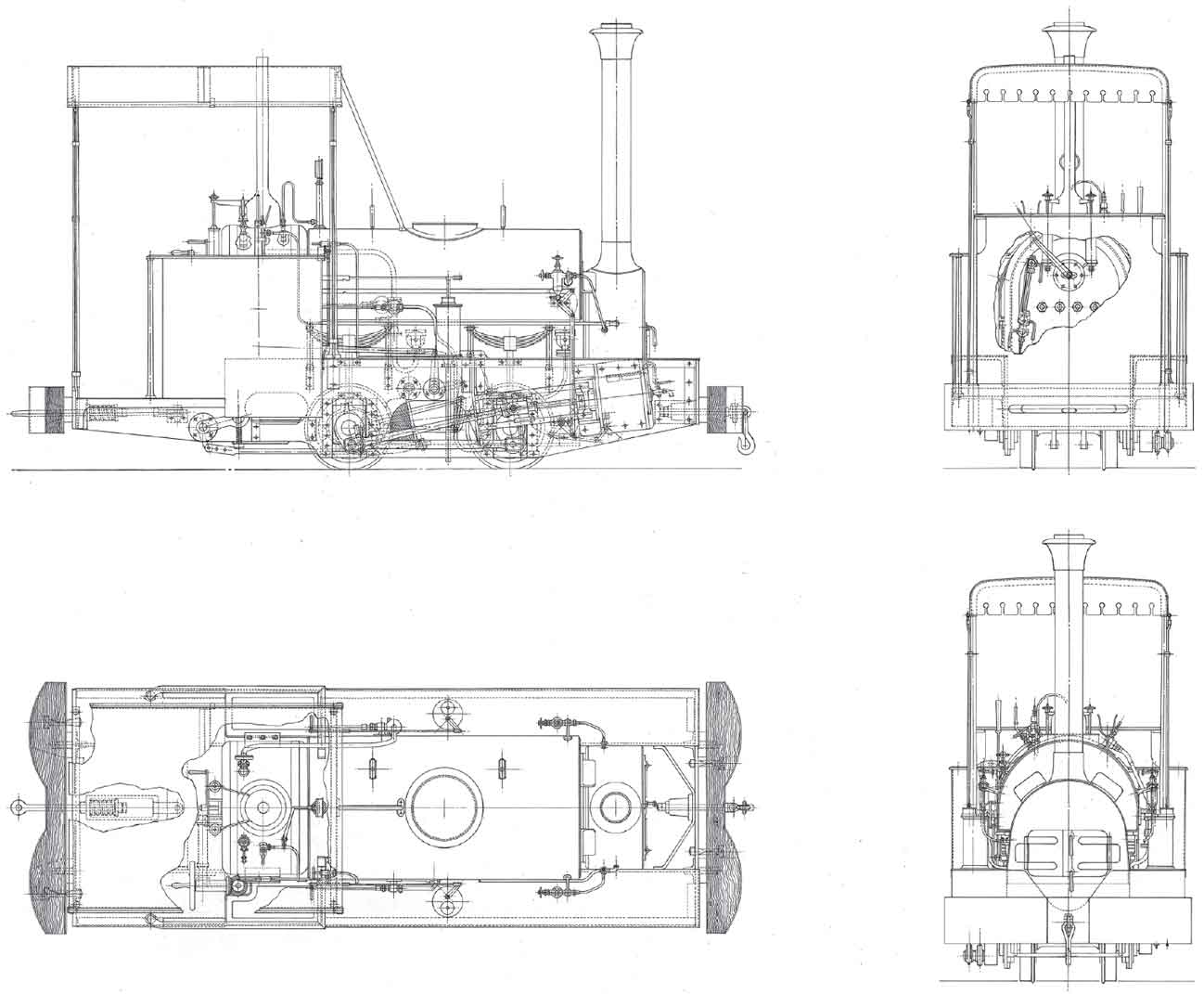
The later mature form of the Royal Arsenal 18in-gauge Manning Wardles is illustrated by this drawing of 1887-built Torpedo. The simplified cab structure, cab footplate of uniform width with the leading portion of the locomotive and Manning Wardle-pattern injector are much in evidence. (The late R. Smithers)
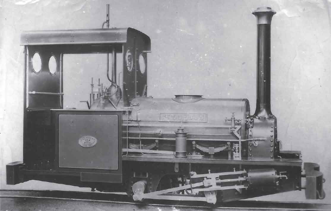
The final ‘as built’ form of the Woolwich narrow-gauge Manning Wardles is shown in this view of Arquebus (Manning Wardle Works No. 1130 of 1889). By this stage of development, all canopy fringes had been dispensed with (facilitating the fitting of a rain strip from new), and the fitting of waist sheets and spectacle plates had produced something approaching an enclosed cab. The footplate layout changed little from the second locomotive of the series (No. 477 of 1877), save for widening at the rear end (so as to be flush with the coke boxes), dispensing with the wooden flooring, incorporating later pattern Dewrance’s water gauges and mounting a Beck’s patent whistle on the cab roof. Other detail differences would have included the substitution of a Manning Wardle injector for the earlier Giffard pattern (as with Torpedo) and dispensing with the tank handrails. Roscoe cylinder lubricators are also very much in evidence, mounted on the leading parts of the tank sides. (Maker’s photograph)
The experimental work of Lieutenant Colonel F.E. Beaumont concerning the use of compressed air as an alternative source of motive power to steam has already been considered in greater detail and there is nothing further that can be added here regarding the prototype 18in-gauge compressed air locomotive of 1877, nor Fox Walker 386 of 1878, save for the fact that neither appears to have enjoyed long operating careers on the Arsenal’s railway system. There is an outside possibility that the Fox Walker locomotive may have seen use on a railway system constructed by the Royal Engineers from 1886 onwards to serve the Brennan Torpedo Installation at Fort Camden in County Cork (now in the Republic of Ireland), but surviving evidence to prove or disprove this assertion is not forthcoming at the time of writing.
The first non-Manning Wardle 18in-gauge steam locomotive supplied for mainstream use on the Arsenal’s railway system was allocated to the Royal Carriage Department. This was Vulcan Foundry Ltd Works No. 838 of 1878, RCD No. 3 (renamed Iron Duke following the 1891 unification). It seems likely that the main reason for allocating the contract for construction of the locomotive to the Newton-le-Willows maker was a political one, namely the wish not to give one builder a monopoly on the supply of locomotives for military and military support services. It cannot now be ascertained whether Vulcan Foundry’s experience in supplying the gun haulage locomotives over thirty years before played any part in their choice as a supplier to the Arsenal. Be that as it may, Iron Duke bore a strong resemblance to its Leeds forebears in its general appearance, although its wheelbase was longer by 6 inches, its wheel diameter was increased by an inch and the cylinder dimensions were 7in x 9in. As with the Manning Wardles, Iron Duke was fitted with an axle-driven feedpump and a single injector, an arrangement that was to remain standard for all new 18in-gauge steam locomotives designed specifically for use at the Arsenal until 1915. This latter set of dimensions is interesting in one important respect, namely that 7in x 9in was the next stock size of cylinder used by Manning Wardle after 6in x 8 in. The earliest recorded use of this cylinder size by the Leeds maker was on two inside-framed 2ft 6in-gauge 0-4-0STs in 1883 (Works Nos 878–9) that were constructed in a similar general style to the Woolwich and Chatham-class locomotives (two later Manning Wardle products probably used the 7 x 9 cylinder castings bored out to slightly smaller diameters, these being 2ft-gauge 0-4-0ST Works No. 1371 of 1897 Colonel Wilson and 3ft 10in-gauge 0-4-2ST Works No. 1660 of 1905 Lamplough Wickman, the latter possessing a rounded water tank of similar shape to those used on the 18in-gauge locomotives). The question therefore arises as to whether Manning Wardle tendered a 7in x 9in proposal for the locomotive that became RCD No. 3, only to be defeated by the considerations detailed above (possibly with the cylinder patterns being used in the manufacture of Nos 878–9). Given the zeal of the Leeds manufacturer in pursuing orders for locomotives for use at Woolwich and Chatham (see also the company’s role in the story of the Hornsby locomotives discussed later), evidence for the plausibility of such a design proposal is strong, although its existence is unlikely ever to be proved from surviving evidence. Given the enlarged dimensions and particularly the longer wheelbase of Iron Duke when compared with the Manning Wardle locomotives, there is strong evidence to suggest that the Vulcan Foundry product was intended for use on the then embryonic 18in network linking the various shops rather than in the shop areas themselves. It may even be that the Iron Duke hauled the first 18in-gauge passenger vehicles, although this cannot now be known for certain.
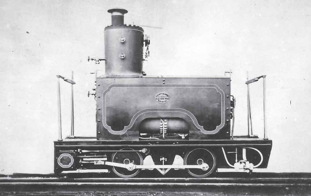
For reasons that have never been fully explained this 0-4-0WT was supplied by Fox, Walker & Co. to the War Department in 1878 as the Makers’ class WATE for use within the Arsenal. Constructed to the same design as Billy (rebuilt) and Dickie of Crewe Works fame, this locomotive (which could be driven from either end) had cylinders of only 5.5in x 6in, wheels 15in diameter and (probably) a working pressure of only 90psi. It would have been of little practical use for the Arsenal’s traffic requirements although, as suggested in the main text, its building date may have been of significance when one takes into account Lieutenant Colonel Beaumont’s experimental work of the period. The locomotive had certainly been disposed of by the Arsenal before 1898 and in all probability several years prior to this date. (Maker’s photograph)
Although the purchase of Iron Duke had demonstrated that the Arsenal authorities were prepared to seek enlarged locomotives from non-Leeds-based sources, a Leeds-based supplier was resorted to for the next group of designs to be supplied for use at the Arsenal. Before discussing these locomotives in detail, it will be helpful to consider the implications of developments relating to the Manning Wardle 6 x 8 0-4-0STs not constructed for use at Woolwich. In all, there were fifteen such locomotives: six of 18in gauge for use at Chatham Dockyard between 1871 and 1899; the similar example of the same gauge for the School of Military Engineering in 1873 already referred to, all of these having rectangular mainframes; three further 18in-gauge locomotives for Argentina between 1890 and 1924 having chamfered mainframes, with an earlier locomotive of the same gauge for Russia in 1875 believed also to possess the same; a 20in-gauge specimen of the same vintage for a Scottish colliery with only slightly chamfered mainframes; a 2ft-gauge 1874-built example again for colliery usage with pronounced chamfered mainframes; and two further 2ft-gauge examples of 1874 and 1877 about which little is known, save for the fact that the earlier example later turned up as a ‘contractor’s locomotive’ on the Darjeeling Himalayan Railway. The importance of this analysis is that a dichotomy opened up at an early stage in the evolution of the Manning Wardle ‘slim gauge’ 0-4-0ST locomotives that was to manifest itself not only at the Royal Arsenal, but also in the sphere of the well-known and largely still extant Quarry Hunslet group of classes built for use in North Wales. The choice of whether to adopt the simplicity and robustness of simple rectangular mainframes or use a configuration chamfered at its leading and/or trailing lower edges was normally determined by considerations of ease of access to areas between the frames, the length of overhang (particularly at the rear end) and the abundance of gradients on the locomotive’s working route. Be that as it may, the next two narrow-gauge locomotives to be delivered to the Arsenal adopted the simple rectangular mainframe configuration, rather in the manner of Manning Wardle Works No. 424 Busy Bee delivered to Chatham Dockyard over a decade earlier.
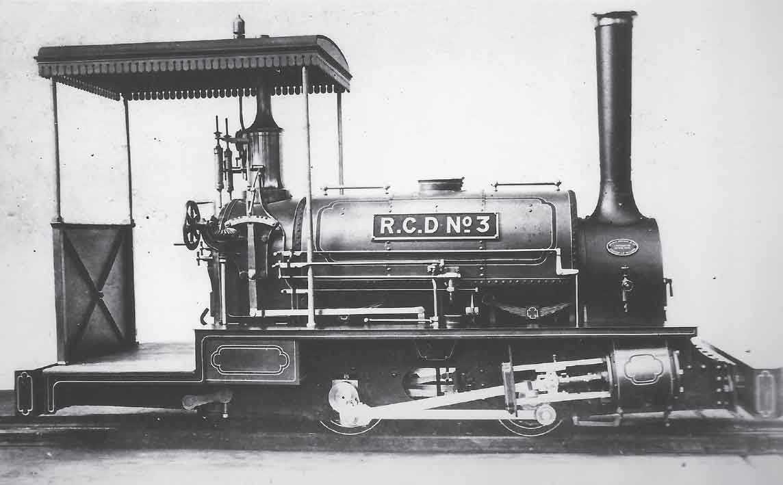
As evidenced by the previous caption, the Manning Wardle monopoly on the supply of 18in-gauge steam locomotives to the Arsenal was broken in 1878 and, in the field of locomotives intended for ‘mainstream’ traffic within the Arsenal, the first movement in this direction was made by the Vulcan Foundry. RCD No. 3 (later Iron Duke) was Maker’s No. 838 and in many respects followed the Manning Wardle lead in its design. Important differences included the longer wheelbase, the suspension of the expansion link from its functional mid-point (rather than the simpler but less mechanically exact bottom-hung arrangement used on the Manning Wardles), and the front end of the mainframes. The maker’s favoured pattern of brass-capped ‘stovepipe’ chimney was also in evidence. Iron Duke remained in service until authorized for disposal in March 1915, being scrapped shortly afterwards. (Maker’s photograph)

This drawing of Iron Duke as built illustrates the constructional details of the design. The longer coupled wheelbase, when compared with the previous narrow-gauge Arsenal locomotives, would have been a major handicap when negotiating curved track in confined shop areas. Was RCD No. 3 designed as a narrow-gauge ‘mainline’ locomotive, only to be superseded when it was shown possible to construct locomotives with even larger cylinders that retained the 3ft 3in wheelbase used by Lord Raglan? (Author)
The first Hudswell Clarke 0-4-0STs to see service on the Arsenal’s 18in-gauge system, Carronade and Culverin, were delivered in 1884 respectively as Works Nos 268 and 269. From the mechanical point of view, their design followed the lead set by their Manning Wardle and Vulcan forerunners, while their general appearance was very representative of their maker’s practice. Indeed it set the pattern for several of the company’s other products, including the well-known 2ft-gauge 0-4-2STs Gwen and Joan for the Oxfordshire Ironstone Company. The familiar Hudswell flat-sided saddle tank was present, along with a wrap-over cab roof and a graceful tall chimney. The familiar Leeds-pattern domeless boiler with raised firebox wrapper (accompanied by a curvaceous brass safety valve trumpet) was very much in evidence, as was the water feed arrangement consisting of the (at this stage mandatory) single injector supported by an axle-driven feedpump. Carronade and Culverin reverted to using the 3ft 3in wheelbase found on the Manning Wardle locomotives but were altogether more powerful, being fitted with 2ft 1in diameter wheels and 7in x 12in cylinders. The maker’s drawings list survives and reveals the fact that while many of the components for these locomotives were of new design, others were adapted from earlier products; in particular the valve motion was derived from that used on Works No. 167 (a ‘Quasi-Fell’ 2ft-gauge 0-6-0ST constructed for Westbury Iron Co. in 1875).
As with the Manning Wardle locomotives, customer requirements dictated design changes and during the next five years, Hudswells supplied seven further locomotives recognizably similar in appearance and overall dimensions but incorporating various improvements and detail changes as the years passed. On the Achilles sub-grouping of four locomotives, Works Nos 273, 274, 280 and 281, the mainframes were redesigned so as to be longer at the rear to accommodate a longer cab and footplate (with associated new design of coke boxes), while four sandboxes of new design (the leading pair mounted above footplate level under the leading edge of the tank and the trailing pair concealed within the cab area) replaced the previous two mounted between the mainframes. The slide valves, link motion, weighshaft and wheels were also of new design. The next development was represented by Works Nos 288 and 345 (respectively Basilisk and Militades), which retained the same thirty-six-tube boiler design (2ft 3in barrel diameter) that had been used on No. 268, but once again the chassis was redesigned, with new drawings being issued for the cylinders, main steam pipe, mainframes, wheelsets, valve motion, weighshaft and suspension. In addition, the alteration of the chassis design had the knock-on effect of necessitating redesign of the cab and coke boxes. The 1887-built RL No. 6 (Works No. 295) was the last nineteenth-century variant of the group to emerge, and the design was further modified to accommodate more severe height restrictions and undulations in track level in the Royal Laboratory area. The lower leading and trailing edges of the mainframes were therefore chamfered, necessitating new frame drawings (along with new drawings for the cab, coke boxes and reverser), the chimney was shortened and the footplate lowered at the trailing end. Significantly, the boiler (and probably the tank) was of new design, although sadly the relevant drawings do not survive to show how the new boiler differed from the previous pattern. The engine’s remaining components were largely the same design as those of Basilisk, although the steam chest cock and associated linkage were also of a revised design. This type was designated by the makers as the Gemini class, although its solitary representative was named Grenade after unification in 1891.
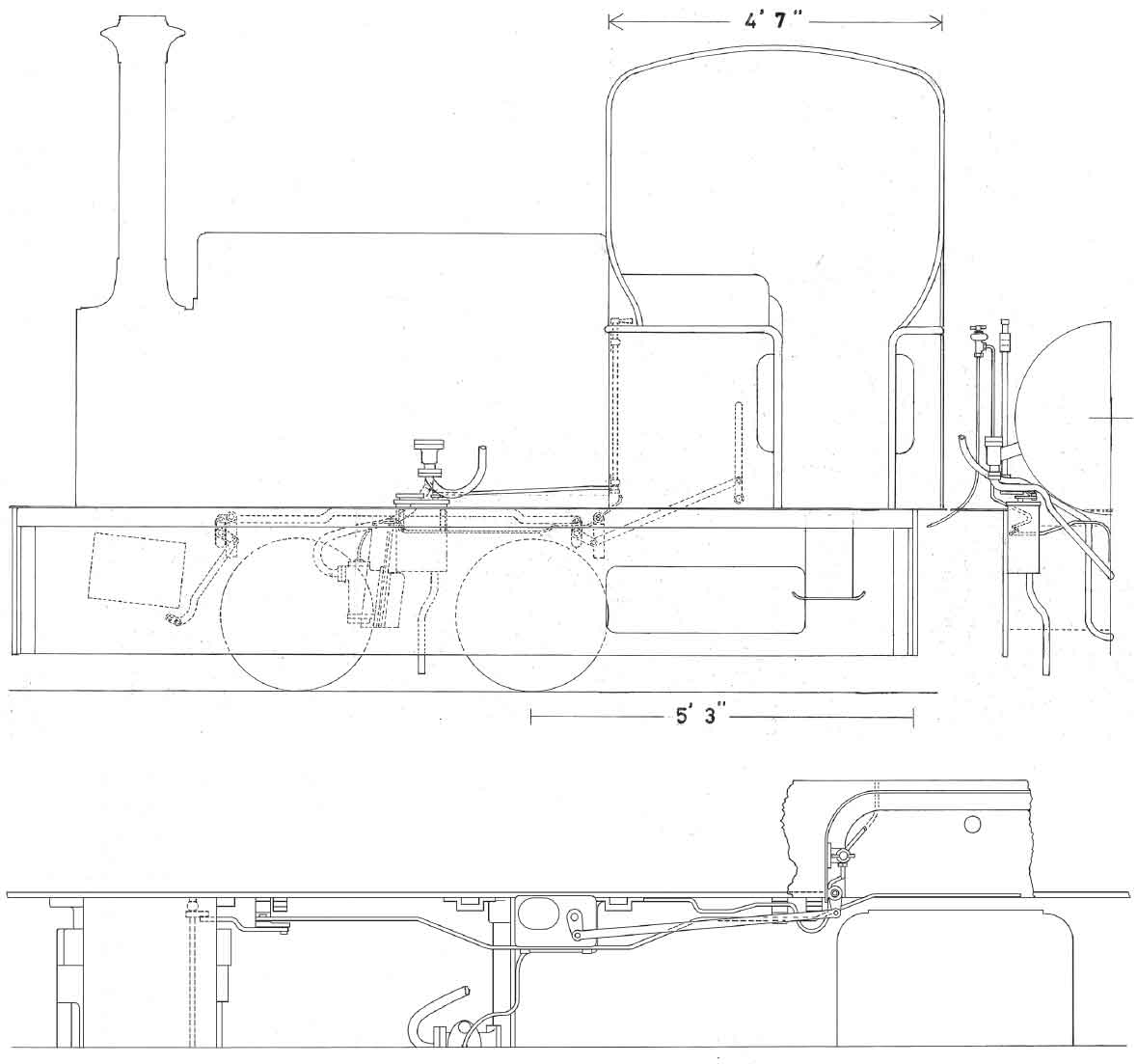
This drawing highlights the detail differences between the first two Woolwich 18in-gauge Hudswells and the second sub-group. The shorter rear overhang, provision of only two sandboxes and the necessary path of the draincock linkage are readily apparent. (Author)
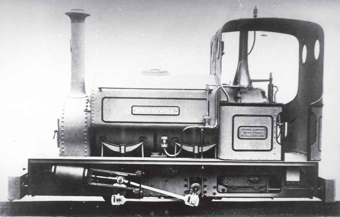
This view shows the first of the Hudswell Clarke 0-4-0ST locomotives for use on the Arsenal’s 18in-gauge system. Works No. 268 of 1884 Carronade was styled very much in the manner of its larger sisters, although the drawgear was, as would have been expected, made to the standard Arsenal specification. As with the preceding Manning Wardle and Vulcan locomotives, the Hudswell narrow-gauge specimens of the nineteenth century either bore names with a military or munitions connection or departmental numbers. The basic design owed much in its inspiration to Hunslet and Manning Wardle narrow-gauge locomotives of the preceding fourteen years (note the domeless boiler with raised firebox, saddle tank, one axle-driven feedpump and one injector, and rectangular mainframes of a pattern seen on Manning Wardle’s Busy Bee for Chatham Dockyard). Despite the fact that only two locomotives of this precise specification were turned out, the entire Hudswell Clarke 7in x 12in group was often given the class name Culverin after the second locomotive, No. 269. Some authorities within the Arsenal preferred the class name Militades after a member of the more prolific second sub-group. In all, four variants of the basic specification were eventually constructed for use within the Arsenal, including the ill-fated final batch of five in 1915. (Maker’s photograph)
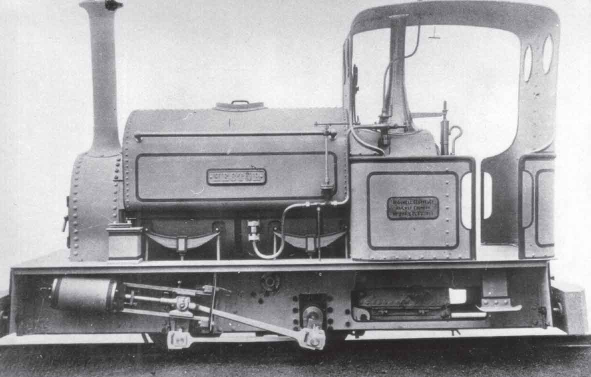
The second sub-group of the Hudswell Clarke 7in x 12in specification is illustrated by this photograph of Hector (Works No. 274 of 1885). Hector had a sister engine Achilles (273 of 1885) and they differed from Nos 268–9 mainly due to a longer cab and rear overhang, and the fitting of four sandboxes instead of just two, in this case mounted wholly above footplate level. Once again rectangular mainframes were used, which must have hampered the locomotives’ usage in areas where steep gradients abounded. During the following year, as referred to in the main text, there was a redesign of the basic type (commencing with No. 288 Basilisk) resulting in alterations to the design of much of the area below footplate level. (Maker’s photograph)


Unfortunately, surviving drawings for the main variants of the nineteenth-century RAR 18in-gauge Hudswell 0-4-0ST specification are far from comprehensive, but it has been possible to reconstruct these drawings of Hector from photographs, engravings, known dimensions and drawings of the later 1915 series. (Author)
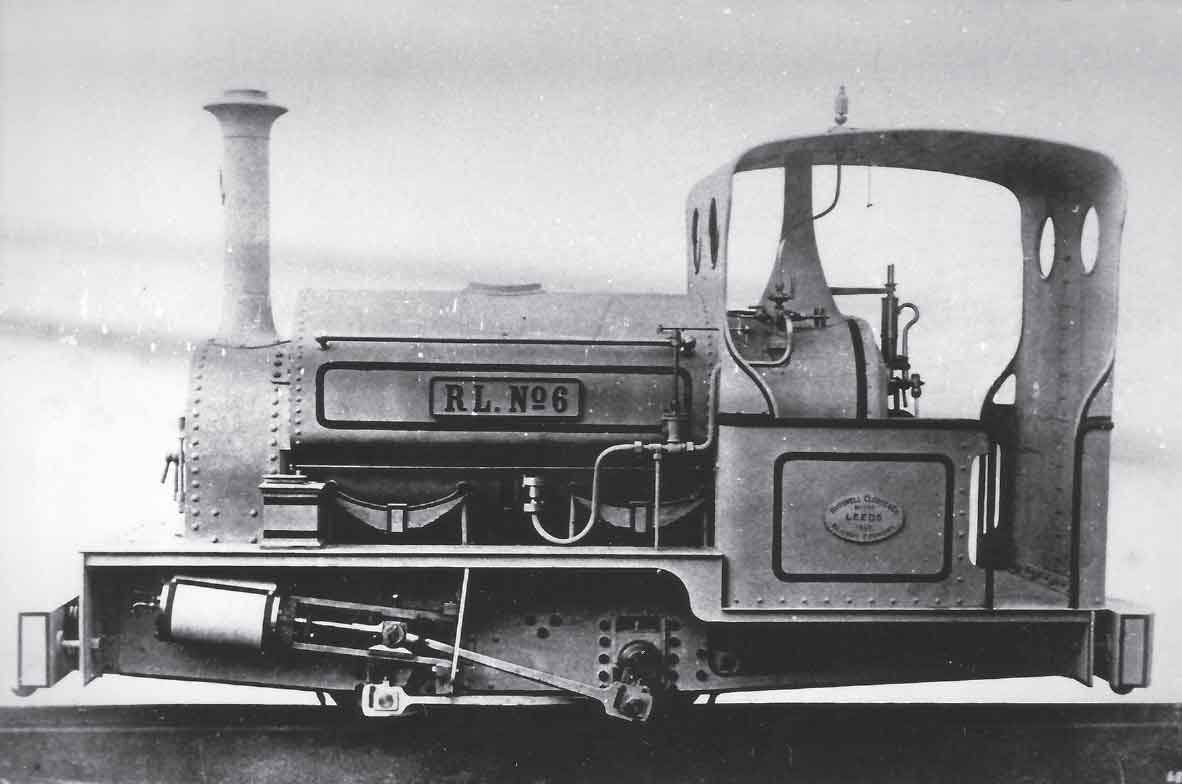
The ‘oddball’ of the 18in-gauge Hudswell Clarke group is illustrated in this view of No. 295 of 1887 RL No. 6, the last new steam locomotive built for the Royal Laboratory prior to the unification of the Arsenal’s railway system in 1891. The most noticeable apparent differences between this locomotive and those depicted in the previous illustration are the cut-down chimney and safety valve trumpet, dropped rear footplate and cab remodelled to fit its lowered position, although in reality a considerable amount of redesign work was undertaken when compared with Basilisk. The Hudswell locomotives proved their worth at the Arsenal sufficiently for a further five to be constructed to an updated specification in 1915. In the grander scheme of narrow-gauge locomotive evolution, an 0-4-2ST version was built to a gauge of 18.25in in 1892 (Works No. 392) for export to St Petersburg. This was developed during the following year into the maker’s Manaos-class 2ft-gauge 0-4-2ST (initially Works No. 414 for Brazil), while a year after that, the cylinder diameter was increased from 7in to 8in, the ‘mature’ class dimension, on another similar locomotive built for the same Brazilian customer (No. 426 of 1894). This latter locomotive paved the way for Gwen and Joan, referred to in the main text. Today an example of the basic specification (No. 1559 of 1925) survives in the Puffing Billy Railway Museum at Menzies Creek, Victoria, Australia. The Hudswell locomotives for the Royal Arsenal spawned other descendants, most notably in the form of a 2ft-gauge 0-4-0ST design with 8in x 12in cylinders (Nos 517 of 1899 and 570 of 1900) for Vickers, Sons & Maxim Ltd of Sheffield, which were sold for scrap in 1932, and a six-coupled design of the same gauge built for North Eaton Sugar Mill, Queensland, Australia, from 1896 onwards, of which a specimen survives in its adopted country. (Maker’s photograph)
In service, the nineteenth-century Hudswell Clarke subclasses appear to have proved their worth well, as evidenced by comments in Leslie S. Robertson’s work and the fact that five further locomotives were constructed to an updated version of the Basilisk specification in 1915. The contrasting story of these later locomotives will be considered in Chapter Nine. As mentioned previously, the basic Basilisk specification was destined to have a lasting legacy outside the confines of the RAR system: Hudswell Clarke Works No. 392 was constructed to the 0-4-2ST wheel arrangement using the same boiler design and most mechanical component drawings, but with redesigned mainframes, suspension and buffer/drawgear arrangements. The locomotive is believed to have been ultimately destined for Estonia, but its design appears to have been the basis (albeit with a pillar cab) of the 2ft-gauge Manaos-class 0-4-2ST Works No. 414 for Brazil. Subsequent enlargement of the cylinder diameter of this latter class from 7in to 8in not only resulted in the construction of the previously-mentioned Gwen and Joan but also of Works No. 1559 of 1925 for Pleystowe Sugar Mill, Queensland, Australia, a locomotive now preserved at Menzies Creek on the Puffing Billy Railway in Victoria State.
Following an abortive proposal for an 0-4-0 inverted saddle tank locomotive Renown in 1894 for Royal Engineers’ direct usage, Messrs W.G. Bagnall of Stafford produced a modified version of the proposal during the following year as Works No. 1442 for the Royal Arsenal. The locomotive was named Ajax and, as with the Culverin type and its derivatives, 7in x 12in cylinders and 2ft 1in diameter wheels were utilized. The inverted saddle tank configuration had been very much a feature of the Stafford maker’s practice from its foundation in 1876 right up to the turn of the nineteenth century but the design’s disadvantages, such as limited water capacity and restriction of maintenance access to the main steam and exhaust piping, ensured that it fell out of favour with potential customers at a relatively early stage of proceedings. Although the final locomotive constructed for direct or front-line Royal Engineers’ usage, Rameses (Bagnall Works No. 1452 of 1896) was built to the inverted saddle tank configuration (albeit with larger 8in x 12in cylinders and a 3ft 6in wheelbase), the reference in Leslie Robertson’s 1898 work to the Ajax class proved to be optimistic as Ajax was destined to be a ‘lone star’ in the RAR fleet.

In 1894 Messrs Bagnall & Co. came up with this design proposal for a new 0-4-0 inverted saddle tank design with 7in x 12in cylinders for military-related usage. It is not clear whether the design was intended for use on the RAR from the outset or whether it was originally intended for use by the Royal Engineers overseas (the enclosed cab suggests the former whereas the Suakin-pattern drawgear suggests the latter, although Bagnalls may have been unaware of the RAR-pattern drawgear design at this earlier design stage). The apparent lack of provision of sanding gear is immediately apparent, as is the Baguley valve gear, although neither of these features would have been likely to appeal to serious military users. Despite the previous efforts of Major Hogg and Captain Kunhardt in favour of 2ft 6in, 18in gauge was still the narrow-gauge order of the day at this stage for front-line duties and remained so until 1896 when the Royal Engineers decided to discontinue ordering 18in-gauge locomotives for direct military use. The locomotive was a simple short wheelbase outside-cylinder 0-4-0 tank (albeit with horizontal cylinders) indicating that by this stage, and contrary to their endeavours with 2ft 6in-gauge locomotives at the time, the Royal Engineers had come round to the view that trailing trucks were not worth their attendant problems on 18in-gauge locomotives. The last 18in-gauge steam locomotive constructed for Royal Engineers’ front-line use, Rameses (Bagnall Works No. 1452 of 1896), was built to a larger 0-4-0 inverted saddle tank specification incorporating 8in x 12in cylinders, 2ft 1in diameter wheels and a 3ft 6in wheelbase. It was equipped with RAR-pattern drawgear despite being sent to Sudan when new and was destined to end its days there, never seeing service at Woolwich. (Maker’s catalogue)
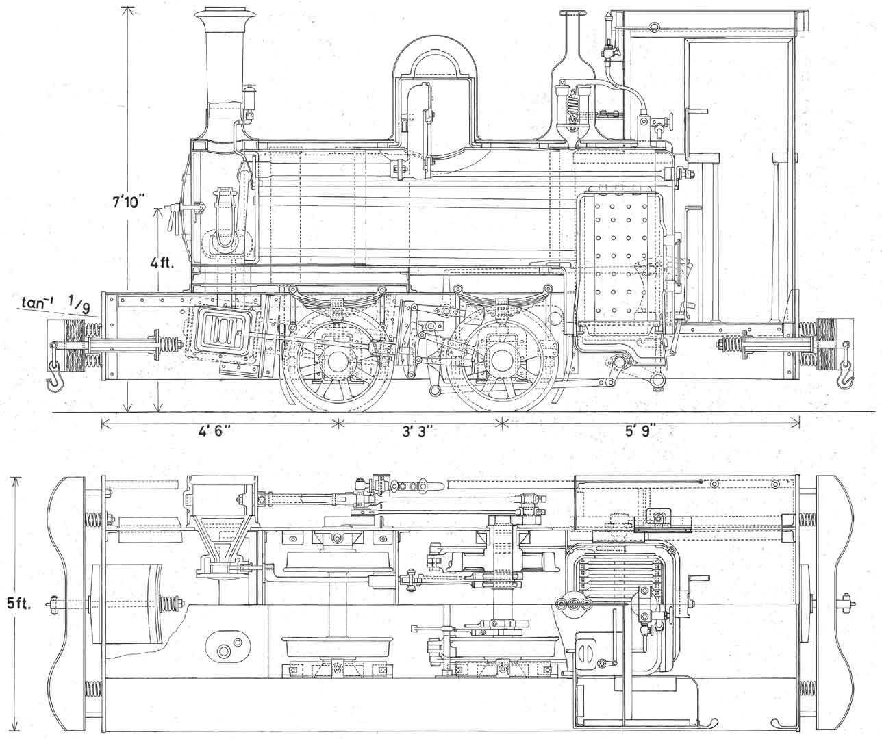

Above and below: These drawings are intended to show the design features of Ajax as built. They comprise a section and plan view; left-hand elevation; front and rear views; and right-hand details. Certain details pertaining to the working of the leading sanding gear are not shown on the maker’s original documentation and have had to be inferred, although the leading cross tie rod arranged to pass through apertures in the mainframes below footplate level would have been necessary. (Author)


Although the design of the Royal Arsenal Railways’ Ajax was clearly influenced by the Renown proposal, the substitution of inclined cylinders with Stephenson/Howe motion for the proposed arrangement of horizontal cylinders and Baguley valve gear will be noted. Other points to note are the expected substitution of RAR-pattern drawgear for the Suakin pattern proposed for Renown and the configuration of the sandboxes. Rameses (see previous caption) was built with many components standard with a metre gauge inside-framed class (Maker’s Nos 1447–51), but itself followed Ajax in many details, not least in the use of outside frames and link motion, although its ‘cab’ simply consisted of four pillars and a roof, more appropriate for conditions in Sudan. (Maker’s photograph)
Notwithstanding the failure of Beaumont’s earlier experiments with compressed air as a source of motive power on the Arsenal’s railway system, a pressing need was still felt for a safer alternative to the steam locomotive where the presence of dangerous munitions was seen to be a threat to life and limb. The latter part of the nineteenth century had seen the emergence on the commercial scene of a new entrant, namely the internal combustion engine, with its reliance on the burning of hydrocarbon fuel within the cylinder area rather than on a separate supply of externally-generated steam. The elimination of a separate firebox thus offered the possibility of a much reduced fire risk in the vicinity of Danger Buildings, the potential of which was not lost on the Arsenal’s authorities.
The man who was to make the first crucial step in making internal combustion motive power a practicality on the Arsenal’s railway system was born in Halifax, West Yorkshire, on 28 January 1864. Herbert Akroyd Stuart was the son of Glaswegian engineer Charles Stuart who had moved to undertake experimental work at the Bletchley Iron and Tin Plate Works in Buckinghamshire. Educated at St Bartholomew’s Grammar School, Newbury, Herbert is known to have undertaken work as a junior assistant at the City & Guilds of London Technical College, Finsbury, before returning to join his father at Bletchley. After undertaking the work that would pave the way for the development of the locomotives discussed in this volume, Akroyd Stuart (who had incorporated his mother’s maiden name into his own) emigrated to Perth, Western Australia, at the turn of the century where he helped to found Saunders & Stuart Ltd, a company involved in the harnessing of gas power for gold-mining. He died on 19 February 1927, with his remains being repatriated and laid to rest in the cemetery of All Souls Church, Halifax.
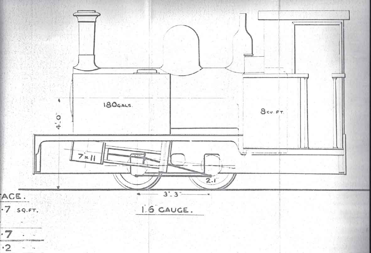
A rare survival is this RAR official diagram for Ajax. It amounts to a simple side elevation view and sadly is not dated. It was accompanied by the following dimensions: heating surface, tubes 113.7 sq ft; firebox 18 sq ft; and grate area 3.2 sq ft. It would appear that similar diagrams were made for the other RAR locomotives but sadly they do not appear to have survived. (Courtesy Mike Swift)
Returning to his period of experimental work, Herbert was slightly injured in an accident on a visit to Llanelli, South Wales, in 1885. This involved the spillage of paraffin from a lamp onto molten tin that resulted in vaporization of the oil, subsequently producing a small explosion when the vapour made contact with the lamp. Seeing this as a possible source of motive power, Herbert returned to Bletchley and encouraged his father to undertake initial experimental work on internal combustion engines, which he eventually took over. Starting with a conventional petrol engine of the period, Akroyd Stuart conducted experiments in which the engine was started with petrol and then switched over to safer paraffin when it had warmed up sufficiently. To aid this process, a progressively increasing proportion of the water jacket was withdrawn from the combustion chamber until the paraffin would ignite of its own accord as a consequence of the heat generated by the engine itself. The next stage was to dispense with the primitive spark plug apparatus of the period and move to pre-heating the combustion chamber until the engine could be started by pumping a small quantity of fuel into the chamber. When working, therefore, the engine’s fuel was injected into the combustion chamber (at this stage of development still truly integral with the cylinder) close to the end of the compression stroke on the Otto cycle (as opposed to being pre-mixed with the air as in a conventional petrol engine). The compression-ignition heavy oil engine was thus born as a commercial proposition, and in conjunction with Charles Richard Binney, Akroyd Stuart filed Patent No. 7146 of May 1890. At this juncture, it should be noted that Akroyd Stuart’s work was well in advance of that being carried out by Dr Rudolf Diesel in Germany.
Although a relatively small number of engines were built to this early patent, they suffered from the teething problems of most prototypes. The workmanship in their construction was not thought to be of a particularly high quality and the proportion of heat generated in the combustion chamber (as opposed to that generated by compression) varied greatly according to the load on the engine and its associated fuel consumption. This caused inconsistencies in the pattern of ignition with varying loads and in some cases a tendency towards ‘backfiring’ (pre-ignition). The answer to the latter problem lay in the design of the combustion chamber and the next step in the evolutionary path was to refashion the chamber to the extent that it became a separate vaporizer, connected to the cylinder only by a narrow neck. The fuel oil would therefore now be injected into the vaporizer chamber on the induction stroke, with air being drawn into the cylinder proper on the same stroke. On the compression stroke, the air in the cylinder would be forced into the vaporizer (which for starting purposes had been heated by a lamp as before) for mixing and ignition to take place at the desired point at the end of that stroke. This arrangement resulted in a more consistent pattern of ignition with varying engine loads and effective elimination of the backfiring problem and, in consequence, Patent No. 15994 of October 1890 was filed, again in conjunction with Charles Binney.
The problem of reliable quantity and quality commercial production was solved the following year when the manufacturing rights of the engine were assigned on a royalty basis to agricultural engineers Richard Hornsby & Sons Ltd of Grantham, who, on the advice of their chief engineer, agreed to market and develop the engines. For engines of over 4hp rating, it was found necessary to water-jacket the vaporizer and its neck to reduce the liability of fracture of the latter component in service and to allow for the higher compression ratios associated with the burning of heavier oils. This was provided for under Patent No. 17073 of 1891. During the ensuing years, numerous sundry improvements ensued and, following production of the first Hornsby-built example in 1892, a total of over 32,000 of various types were eventually produced. In addition to the normal stationary applications, road tractors were produced from 1896, along with the first commercially successful application of compression ignition internal combustion power to a railway locomotive, at least in the United Kingdom.
The first of the Hornsby locomotives to be completed for the Royal Arsenal was delivered on 23 July 1896 to the superintendent of building works there and was given the Maker’s No. 1705 and the name Lachesis by the RAR authorities. Although General Arrangement Drawing 14430 showed a locomotive rated at 12.5hp (most of the component drawings for the locomotive were new and numbered in the 14000 series, although the cylinder block and water jacket assembly were constructed to Drawing Number 12591, while sundry other components bore 12000 series drawing numbers), the locomotive that actually emerged possessed an engine with cylinder dimensions of 11in bore x 15in stroke rated at only 9.5hp. Despite this, the maker’s catalogue continued to describe the locomotive as being rated at the higher power output. In order to adapt the basic Hornsby stationary engine for this particular use, the oil tank was no longer situated beneath the engine and its place was taken by the cooling water tank. From this tank the water circulated, via an eccentric driven pump, through water jackets surrounding the cylinder, vaporizer and fuel oil admission chamber and into an upward-inclined pipe that ran forwards above the connecting rod and crankshaft to the cooling tower. This design of cooling arrangement was taken from Patent No. 6122 of 1894 (originally intended for portable agricultural engines), and involved admitting the water via a junction pipe to a series of parallel perforated header pipes inside the top of the tower. From here, the water cascaded down inside the tower into a collecting vessel at the bottom. Immediately above the level of this vessel, perforations in the wall of the tower allowed cool air to be drawn into the tower by the action of the engine’s exhaust, which was admitted through a pipe, via a hole in the wall, to the internal base area of the ‘chimney’ at the top of the tower. A return pipe ran rearwards to the water tank (which contained a filter so that the circulation process could be completed). The fuel oil tank was placed between the locomotive frames behind the rear axle and oil pump (which was actuated from the camshaft), and in order to ventilate this tank, a tall shaft was located within the leading right-hand area of the footplate.
One interesting departure from the manufacturer’s standard stationary engine practice was that the two longitudinal portions of the engine bed of the first four Hornsby locomotives consisted of simple steel girders from which were anchored the locomotive’s brake hangers. One feature found on many Hornsby stationary engines of the period was a fan that was used to assist the burning of the lamp oil. This was actuated by means of a hand crank and intermediate gear, and belt-and-pulley transmission to ‘gear up’ the speed of the fan blades. This feature was incorporated into Lachesis with the fan being located at the rear left-hand side of the locomotive below footplate level and the hand crank above it within the cab at hand level. The gear to which the crank was attached incorporated a semi-enclosed internal rack whose open side engaged with a small pinion, the shaft of which carried the large pulley. This arrangement has caused confusion to many students of the early Hornsby locomotives over the years who have often mistaken the hand crank gear for a warning gong. For stationary engines of 20hp and above, Hornsbys considered it necessary to incorporate what they termed a ‘self-starter’ consisting of a compressed air reservoir that could be primed, via a valve, by a hand pump. Once charged to the required pressure, this vessel’s contents would be used (again via the necessary valve arrangements) to start the engine once the crankshaft had been rotated by hand to the required position. Although the engine used on Lachesis was rated at less than half the threshold deemed necessary by the makers for a self-starter, the locomotive, along with all subsequent early Hornsby oil locomotives, was fitted with this apparatus with the reservoir being mounted between the frames at the rear left-hand side and the hand pump on the same side above footplate level. Although the maker’s photograph does not indicate the presence of any warning device, other photographs taken after the end of the locomotive’s working life show that a whistle was later fitted (along with many other alterations) which was supplied with air when necessary from the reservoir. Lachesis was illustrated in The Engineer of 4 December 1896.
Although experienced in agricultural engineering technology, Hornsbys at this stage had no experience in the production of running gear for railway locomotives and it was no surprise that they turned to an outside contractor for the supply of the ‘rolling chassis’. The identity of this contractor is revealed by close examination of Drawing 14453, which is endorsed with the legend: ‘All these details were bought from Messrs Manning Wardle & Co. See sheets B2437 of Dec 31st 1895 and B2421 of Dec 16th 1895.’ The drawing, which is in two parts, relates to the wheelsets, coupling and jackshaft rods and suspension components. Close examination of this drawing reveals 1ft 8in-diameter coupled wheels that were standard with the narrow-gauge Manning Wardle steam locomotives previously supplied to the Arsenal. It also shows the characteristic screw-adjusted inclined plane split bearings for the crankpins, used by Manning Wardle for some of its products from the 1890s onwards, eliminating the need for cotter pins. The drawing endorsement was barely needed! Owing to the incomplete nature of the surviving documentation, an important question is thus posed: i.e. how far did Manning Wardle’s contribution to the construction of Lachesis extend, given that the Leeds concern did not, unlike with its compressed air locomotives, allocate its contribution a maker’s number, nor is there any reference in surviving maker’s records to any work undertaken for Hornsbys? In order to answer this crucial question, one has to examine the surviving material relating to narrow-gauge Manning Wardle steam locomotives of the late nineteenth century. If one ignores the fact that the horncheeks and axleboxes of Lachesis were inclined slightly backwards (in order to minimize bending stresses on the jackshaft rods caused by vertical displacement of the axles during suspension movements), the shape of the side mainframes on the locomotive closely resembles that found on 2ft 6in-gauge Manning Wardle 0-4-0T No. 1615 of 1903, the last of three similar such locomotives supplied over a period of seven years by the Leeds company for use in India. Another important point to note here is that the year of supply of the first of these locomotives, No. 1322 of 1896, was the same as that for Lachesis. Just for good measure, the pattern of motion bearings shown in the 1903 works photograph of No. 1615 is also the same as for Lachesis (a surviving General Arrangement for No. 1322 confirms that this pattern was in use on that locomotive), as is the stated coupled wheel diameter of 1ft 8in. Taking all these observations into account, there is little doubt that the rolling chassis assembly for Lachesis was supplied from Manning Wardle’s Boyne Engine Works. Further examination of the records relating to both narrow and standard-gauge Manning Wardles also confirms that the same was true of the canopy components. Although the Leeds company had lost its ability to sell new locomotives directly to the Arsenal authorities in 1889, its influence on RAR locomotive practice did not end in that year.
The power transmission arrangement of Lachesis deserves detailed consideration, and it is known from Hornsby drawings relating to the 2ft 6in and 18in-gauge locomotives completed in 1903–04 that some components at least would have been outsourced. A spur gear on the left-hand side of the crankshaft engaged with another that was loosely mounted on the reverse/speed selection shaft. This latter gear was laterally attached, via a journal, to the left-hand bevel gear of the reverse gearbox which also ran loose on the shaft. The bevel gear engaged with another, mounted above on a vertical shaft on the vertical centreline of the gearbox, which in turn engaged with the right-hand bevel gear (again running loose on the main shaft and with an integral journal running in a gearbox bearing). Between the right- and left-hand bevel gears, the main shaft was surrounded by a rigidly mounted friction cylinder which in turn was surrounded by a grooved selection plate provided with limited lateral but no rotational freedom relative to the cylinder. This plate was configured to be able to engage (when moved sideways) with one of the dogs attached to the inward ends of clutch springs surrounding the friction cylinder. These springs were attached at their outward ends to the inner faces of each of the right and left bevel gears. By this means, selection of forward or reverse gear could be accomplished by swinging the footplate-mounted reverse lever leftward or rightward as desired until secured in its limit of travel by a spring catch. This rotated a longitudinal shaft (mounted slightly to the left of the chassis centreline) upon which was fitted an upwardly projecting bellcrank whose upper end was configured to engage with the selection plate groove. Moving the selection plate laterally to engage with one of the spring dogs would engage either the left-hand bevel gear (which would rotate in the same direction as the input spur gear) or the right-hand one (which would rotate in the opposite direction). The oppositehanded ‘threads’ of the clutch springs were configured so that each, when selected, would tighten around the friction cylinder, producing rotation of the main shaft in the desired direction.
Once the engine was in motion, speed selection was accomplished in a manner allowing for two speeds in either direction as follows: the speed selection pedestal was located on the right-hand side of the cab footplate and upon it in the vertical plane were mounted two levers, each rigged so that they could enjoy a limited inward rotational travel but restrained by a notched bar and dog interlocking mechanism so that their respective movements could not take place together. Each lever was affixed at its lower end to a longitudinal bar upon whose leading end was fixed an upward-projecting bellcrank. Each of these bellcranks was arranged so as to engage at its upper end with its respective spur gear, each of which was mounted (so as to enjoy limited lateral freedom) on the right-hand portion of the main gearbox shaft. These gears, as with their selection shafts, flanked the side mainframe. Rotation of the interlocking bar in the desired direction would thus free the chosen speed lever so that it could be moved inwards by its permitted travel and secured by a spring catch. This would push the chosen spur gear laterally on the gearbox shaft into mesh with its counterpart on the jackshaft. Reversing this process would disengage the previously chosen speed and allow for the interlocking bar to be moved into the horizontal (‘neutral’ position preventing movement of either lever) or ‘alternative’ position facilitating selection of the other speed. The Hornsby catalogue claimed a performance for a locomotive of this type of haulage of 70-ton loads on the level at a speed of 3 miles an hour or 40 tons at 5 miles an hour.

The Royal Arsenal authorities did not give up on the quest for safer alternatives to steam motive power in the vicinity of Danger Buildings following the unsatisfactory results with compressed air units in 1877–81. In 1896 Richard Hornsby & Sons Ltd of Grantham produced the first of five medium-to-heavy oil ‘hot bulb’ four-stroke compression ignition locomotives for use in Danger Buildings on the RAR. Four of these were of the customary ‘single piston’ variety and the earliest example, Works No. 1705 of 1896 Lachesis, is shown in this front right-hand three-quarter maker’s photograph. The unit essentially consisted of an ‘ordinary’ maker’s-pattern oil engine with ‘agricultural’-style water cooling system and geared transmission mounted on a modified steam locomotive pattern chassis. In order to adapt the Akroyd engine to this particular form of use, the fuel tank had to be relocated from beneath the engine assembly (where its place was taken by the water tank) to beneath the canopy footplate on the right-hand side of the locomotive. The reverse gearbox (immediately behind the cooling tower) will be noted, as will the speed choice gears (in the foreground and controlled from the pedestal on the right-hand footplate) and final jackshaft drive to the rear axle. Close inspection of the mainframes reveals their similarities (apart from the sloping horns to minimize suspension loadings on the jackshaft rod) to Manning Wardle 2ft 6in-gauge 0-4-0Ts Nos 1322, 1526 and 1615 for India; the same is true of the motion components and bearings. The canopy is recognizably similar to the design found on Manning Wardle 18in-gauge 0-4-0STs Nos 1201, 1818 and 2039 for Argentina (although the supporting brackets on the upper ends of the leading stanchions have been rotated inwards by 90 degrees to engage with the leading canopy valence rather than the side valences), while the 1ft 8in wheel diameter found on all the Manning Wardle locomotives mentioned in this caption was also found on Lachesis. All these features would have been strongly indicative of a Manning Wardle origin for most of the ‘rolling chassis’ of Lachesis, even if Hornsby Drawing No. 14453 had not survived to prove the point beyond doubt. The 1895 date found on Drawing No. 14453 for the wheelsets, suspension and axleboxes of Lachesis suggests that Manning Wardle supplied its rolling chassis and jackshaft rods to Hornsby in the early months of 1896. (Maker’s photograph)
The location of the transmission gearing on Lachesis caused something of a headache from the chassis design point of view in the provision of adequate lateral staying at the leading end as it precluded the mounting of a conventional frame stretcher in the position level with what would have been the motion brackets on a steam locomotive. This difficulty was partly solved by anchoring the rear of the cooling tower to an asymmetrical stretcher between the upper extensions of the mainframes (which secured the reverse gearbox), and anchoring the bottom of the cooling tower at its leading end to the front bufferbeam. Although this arrangement appears to have proved adequate during the early years of the locomotive’s existence, it was, as we shall see, superseded on the subsequent early Hornsby locomotives.
During the first decade and a half of independent locomotive operation, with the exception of units built for experimental purposes, the Royal Arsenal authorities had been able to choose the locomotives that were purchased for use in ordinary traffic on the internal railways. However, the position was to change dramatically after this time as a consequence of historical events elsewhere. In order to understand why this was the case, it will be constructive to review these events and their impact on the railway practice of the Royal Engineers in greater detail. From 1870 until 1896 (for locomotive haulage) and 1900 (for hand or animal working) the Royal Engineers adopted 18in gauge as its ‘trench tramway’ gauge and lines built to this dimension were designated to be used in connection with the support of military sieges regarding such duties as supply and armaments conveyance, water transport and the construction of wider-gauge railways. The earliest experiments in this respect were carried out at Aldershot in 1872–4 with John Barraclough Fell’s ‘trestle railway’ utilizing a long-wheelbase Manning Wardle 0-6-0 Ariel (Works No. 412 of 1872) fitted with safety guide wheels. Failing to gain satisfaction with this rather impractical system (ostensibly on the grounds of its non-adoption elsewhere), the Royal Engineers turned to another possible solution in their attempts to solve the problem of transporting men and materials over difficult terrain. The idea that they experimented with was the ‘Handyside Steep Gradient Apparatus’ patented between 1873 and 1876 by Henry Handyside. This was tested in the latter year by a standard-gauge Fox, Walker 0-6-0ST on the Hopton Incline of the Cromford & High Peak Railway. In essence it allowed locomotives to operate in their normal mode on the level but on gradients of between 1 in 20 and 1 in 10, the locomotive could ascend light and, by means of special gripping struts, be held at some point on the incline. A built-in steam winch would then be used to haul the wagons to the point of rest where they would be held, possibly by means of gripping struts, while the locomotive ascended further, paying out the towing cable as it went until the ascent was completed in a caterpillar fashion. The Royal Engineers were sufficiently impressed with the basic principle to purchase six Handyside 2-4-2T locomotives, Works Nos 399–404, from Fox Walker & Co. of Bristol in 1878, two of which were tested on the eastern part of the Arsenal’s railway system and a third at the School of Military Engineering in Chatham.

This rear right-hand three-quarter view of Lachesis shows the handbrake column (covered by a conical valence), the handwheel and first (internally-toothed) pinion for the fan supplying air to the hot bulb lamp, the cover and exhaust pipe for the hot bulb lamp, the ‘speed gear’ pedestal, and much of the detail pertaining to the cylinder, camshaft and connecting rod. The cooling water was pumped from the cylinder water jacket though the ‘thin’ pipe (as opposed to the ‘thick’ main exhaust pipe) to entry via a manifold to perforated header pipes located within the top of the cooling tower. The water would then drop through the inside of the tower, being cooled by the upward draught induced by the main exhaust, whereupon it would be collected at the base and recirculated through a filter located beneath the cylinder assembly. (Maker’s photograph)
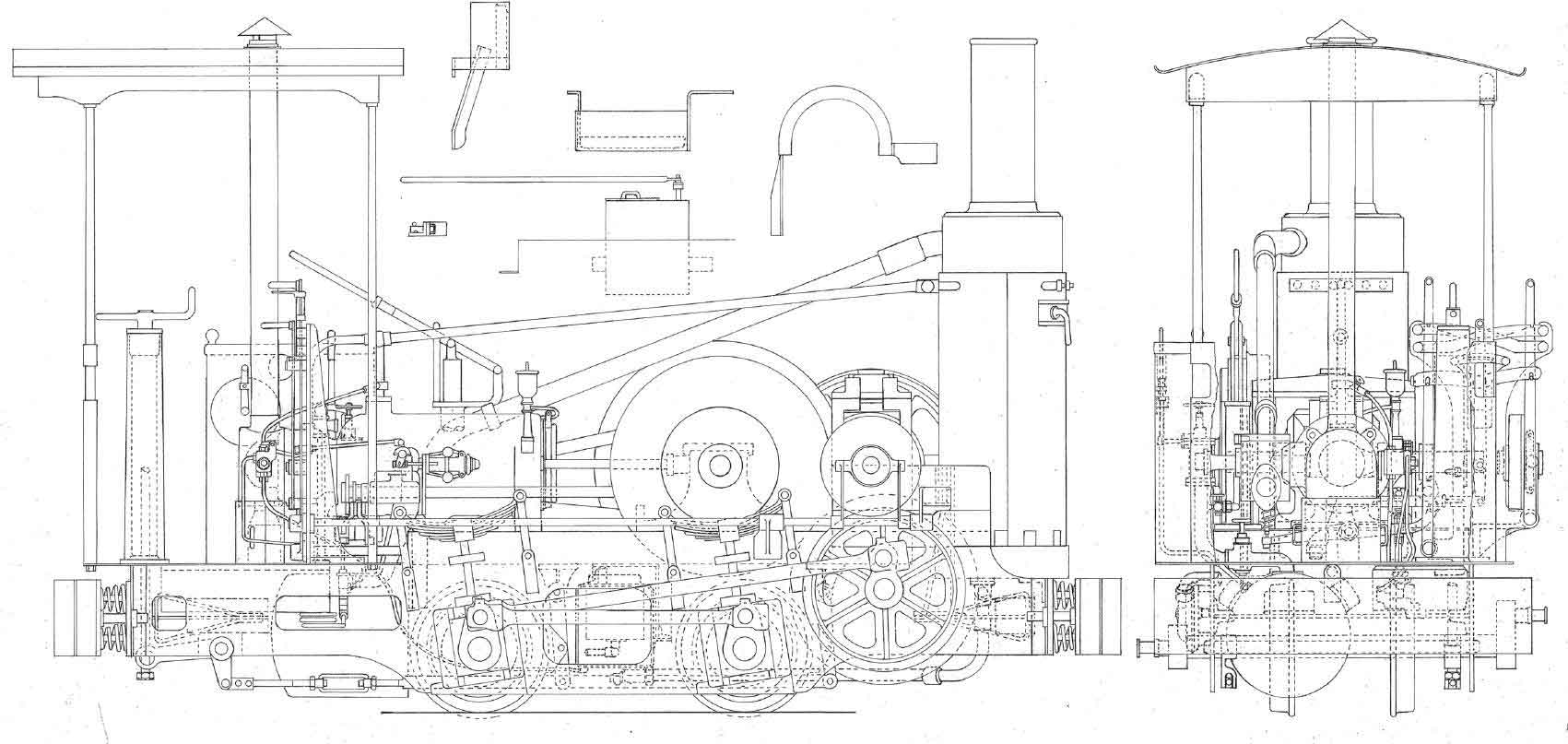
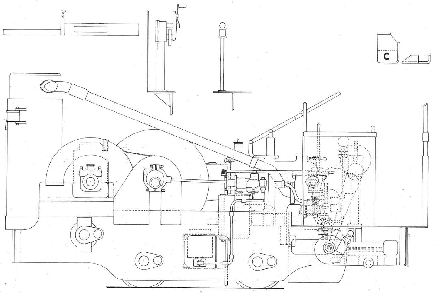
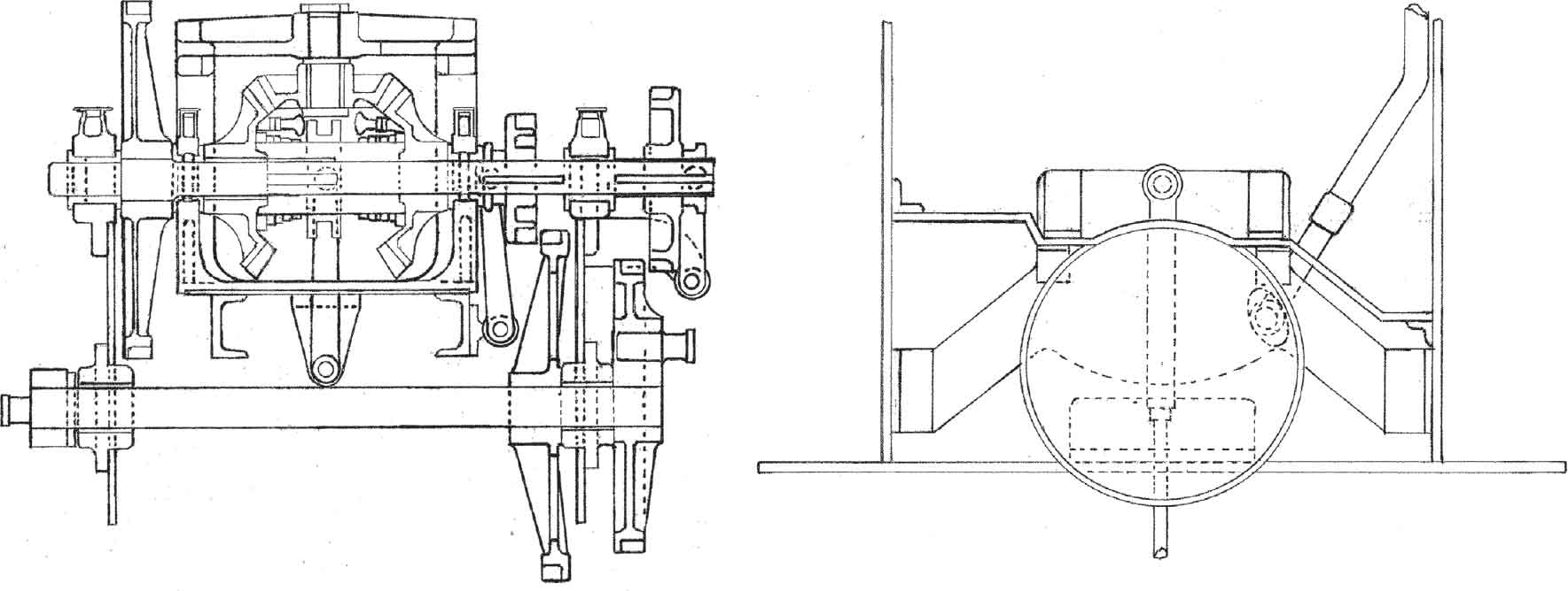
These are reconstructed drawings of Lachesis from the known details, surviving R. Hornsby General Arrangement No. 14330 and the few surviving Component Drawings 14178, 14321, 14453, 14587 and 14613. The first drawing comprises a right-hand elevation showing such details as the speed selection gear, oil injection apparatus, governor, camshaft, water return pipe and (in ‘exploded’ form) the right-hand sandbox and guard for the extreme right-hand speed gear. A feature of special note is the design employed for the drawbars, in which the flexibility was obtained by the use of integral triangular forgings. One note of caution in reading the drawing is that the fuel oil delivery pipe from the pump (the pump being actuated by the air admission rocker) overlies part of the water return pipe from the cooling jacket for the oil admission chamber for the vaporizer. Appended to the right-hand elevation is a rear elevation showing (left) the hand fan for the vaporizer lamp and air starting reservoir with pressure gauge, valves, pump and associated piping with (directly above) the oil engine ‘valve box’ and exhaust pipe. Moving towards the centre, the vaporizer can be seen with (shown by dotted lines) the preheating lamp and air pipe from the hand fan (shown cut away). Beneath the cylinder can be seen the air admission rocker, while mounted on the right-hand side of the vaporizer can be seen the water-jacketed oil injection chamber. The pipework associated with this comprised a loop from the water circulation system for the jacket and an oil connection from the pump with an overflow connection returning to the fuel tank, whose level of usage would be determined by the action of the governor. On the right-hand side of the footplate can be seen the handbrake column, almost certainly of Manning Wardle manufacture but ‘disguised’ by a conical valence, and (in a more forward position) the speed selection pedestal, with its associated anti-simultaneous selection interlocking gear visible.
The left-hand ‘scrap’ view shows such details as the exhaust pipe leading to the cooling tower, the water circulation pump and piping, the compressed air starting reservoir and associated valves and pump, and the guards for the left-hand flywheel and intermediate transmission gearing, while the safety shield for the oil engine connecting rod (omitted from the right-hand view) is shown in place. The components shown in ‘exploded’ view are the guards for the transmission gearing, the pedestal for the vaporizer lamp fan gears and upper pulley, the oil tank vent and the plan and rear-end views of the cab step (the portion marked ‘C’ being of chequer-plate configuration).
The third view shows the transmission system employed by the Hornsby locomotives at Woolwich. The forward/reverse selection shaft (actuated by a lever on the footplate) ran longitudinally along an axis bisecting the body of the reverse gearbox (but offset to the left from the centreline of the locomotive). From this, a bellcrank engaged with a sliding collar on the driveshaft which was fitted with recesses so as to be able to engage one or other of the dogs on the contra-wound forward or reverse springs, one of which was attached to the left-hand bevel gear and the other to the right-hand one. The bevel gears were permanently in mesh, with the left-hand one being integral with the intermediate transmission gear, and both left- and right-hand bevel gears were free, when in neutral, to rotate relative to the driveshaft. Selection of forward or reverse gear would cause the collar to grip one of the spring-dogs, thereby causing the spring to grip a drum mounted on the driveshaft and engage the drive in the desired direction. The two longitudinal shaft and bellcrank assemblies for the speed gears can be seen on the right-hand side, with the interlocking mechanism being visible, as previously referred to, in the rear elevation of the locomotive.
The final view shows the leading drawbar stretcher. Its configuration was determined by the position of the transmission gearing. It had to be incorporated into a subframe with the cooling tower body and its associated frame spacer in order to (theoretically) create a suitably rigid front-end assembly for the locomotive. In reality, the arrangement did not prove to be satisfactory in service. (Author)
It was clear from the test results that although at least some elements within the Royal Engineers did not dismiss the ‘Handyside principle’ out of hand (although they envisaged the winch apparatus being accommodated in a separate truck, presumably with a ‘ball and socket’ flexible steam coupling to the locomotive), there were a number of problems with the locomotives from a mechanical point of view. Their design had been somewhat hurried, owing to the threat of Britain being involved in a conflict in the Balkans in 1878, they lacked a suitable coiling apparatus for the winch, and initially at least their reliability was poor. With the immediate threat of a Balkan conflict gone, in 1881 the RE Committee decided that further 18in-gauge locomotives for siege train purposes were not necessary, but other events during the following two years forced a de facto re-think of the situation. During 1882, some six locomotives of 18in gauge built by John Fowler & Co. of the Steam Plough Works, Leeds, had been supplied for military purposes, probably construction work, in Cyprus and India. These were built under Greig & Beadon Patent No. 402 of 1880 and employed an indirect jackshaft drive in order to keep the cylinders, connecting rods and big end bearings further away from possible damage caused by dirt and lineside obstructions. Nearer home, two locomotives were required for an 18in-gauge construction railway linking Forts Luton, Horsted, Bridgewoods and Borstal on the outskirts of Chatham. The opportunity once again arose for the design of an 18in-gauge locomotive suitable for possible call-up for direct military purposes and it was seized upon by Major Thomas English RE, who had probably been involved with improvements to the design of the Greig & Beadon locomotives and had definitely been involved with the supply of two of them to Cyprus. What eventually emerged for the Chatham system was an 0-4-2 back tank with integral equalized ‘spring beam’ suspension (as used on the later Greig & Beadon locomotives) for the coupled axles, 7.5in x 12in outside cylinders and valve chests, a ‘middle dome’ boiler barrel and Belpaire firebox, inside Gooch ‘stationary link’ motion actuating the valves through rocker shafts, three-piece side mainframes (linked into a single assembly by their stretchers) to accommodate the firebox and trailing truck, and a design of trailing truck credited to Major English under a void patent application (No. 3869 of 1883) that involved side control by means of a sprung ‘crankshaft’ assembly. This truck design was later to be employed on four of the RAR Hornsby locomotives as built, with the prototype eventually following suit. The ruling gradient on the locomotive-worked main line of the Chatham Fortifications system being only 1 in 43, thoughts of using a Handyside winch were quietly abandoned and the minimum recommended curve radius for the new design was 35ft instead of 15ft for the Handysides.
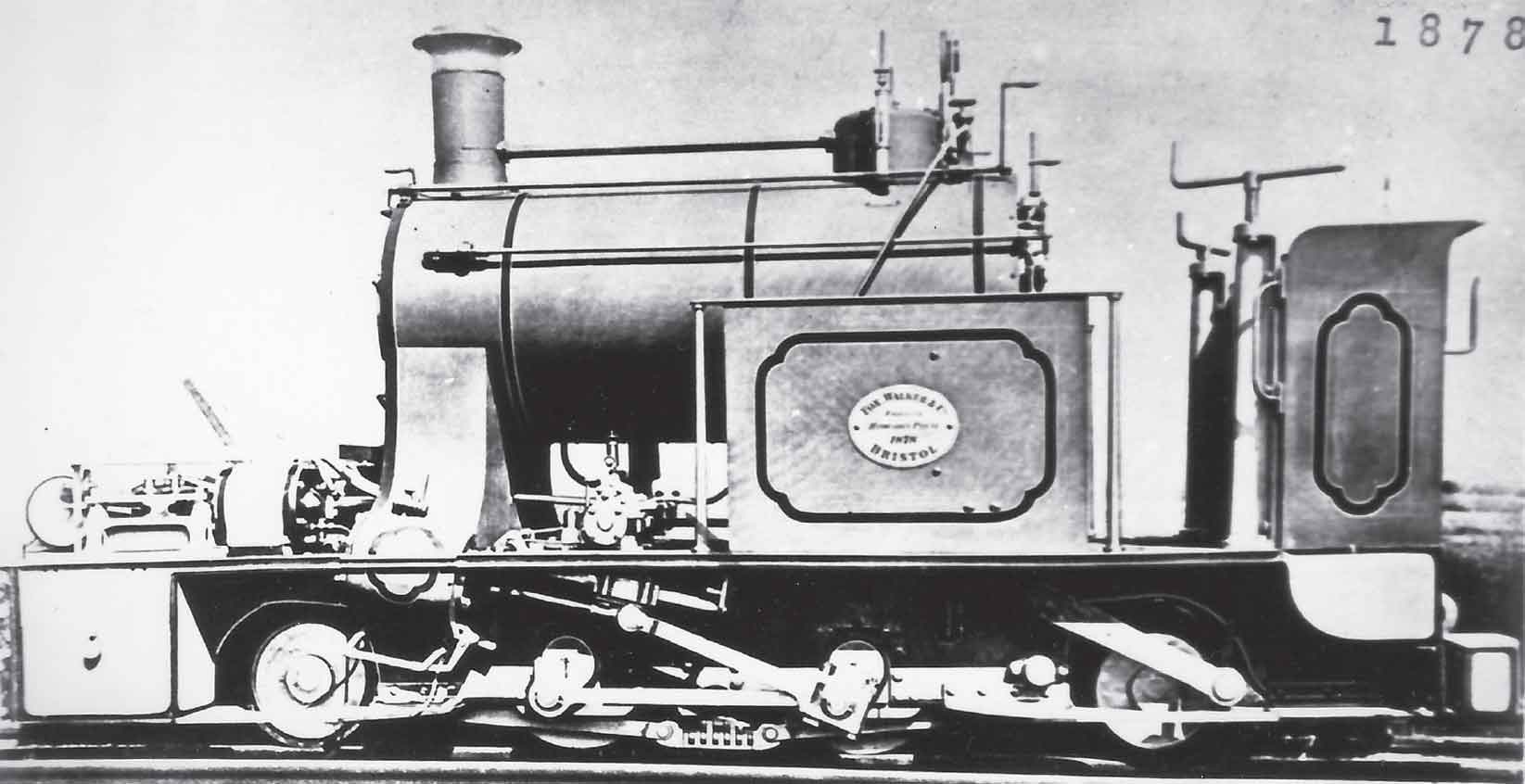
As we have seen, one of the most obvious consequences of the unification of the Royal Arsenal Railways system and its takeover by the Royal Engineers for instructional purposes was an influx of Royal Engineers’ locomotives rendered surplus to other requirements by such factors as the failure of the 1885 Suakin campaign, the 1896 decision of the Inspector-General of Fortifications to dispense with locomotive haulage on front-line 18in-gauge track, and the completion of substantive building work on the Chatham Eastern Defences. The aftermath of this latter event was to make the Eastern Defences (or Borstal line) redundant. One of the most peculiar designs to pass through Royal Engineers’ hands was represented by the six Fox Walker Handyside 2-4-2Ts of 1878 (Works Nos 399–404) originally ordered in response to the threat of unrest in the Balkans, but found to be unfit for their intended front-line purpose after trials on Erith Marshes and at Chatham. This illustration shows the class as originally delivered to the Royal Engineers and emphasizes the gripping shoes for holding the locomotive on steep gradients and the front-mounted winch for the haulage of rolling stock on steep gradients. (Maker’s photograph)
At the time of ordering the new locomotives, Major English would probably have liked to use John Fowler & Co. as supplier (as he had strong links with the firm), but he was overruled by his colleagues who perceived Vulcan Foundry as a better bet. The locomotives therefore emerged as Vulcan Works Nos 939 of 1883 Vulcan and 1075 of 1884 Mercury and were put to work hauling convict carriages on the Fortifications line.
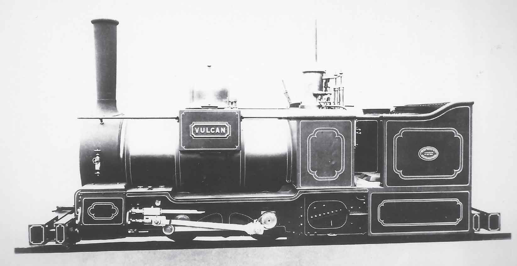
Despite assertions in the Royal Engineers’ Committee Minutes in 1881 that new narrow-gauge locomotives for siege purposes were not necessary (the Balkan threat having long receded), it was decided by the RE shortly afterwards to order two new locomotives for use on the Medway Fortifications. The locomotives were constructed by the Vulcan Foundry as Works Nos 939 of 1883 Vulcan and 1075 of 1884 Mercury. Despite their use of a non-standard pattern of buffers (intended to be compatible with the convict carriages used on the Fortifications line), the locomotives, which were designed by Major Thomas English RE, were clearly intended to form part of a strategic reserve for front-line service and in 1885 they were requisitioned for use on the 18in-gauge railway associated with the abortive Suakin campaign. Following the failure of this campaign in May 1885, they were repatriated and used in ‘double-single’ experiments carried out by Thomas Russell Crampton at the Arsenal before disappearing shortly afterwards. A sad end for these fine locomotives, even if the balance of Royal Engineers’ opinion was that they did not cover themselves with glory in the sandy and arid conditions of Sudan. (Maker’s photograph)
Shortly after the delivery of the two Vulcan locomotives to Chatham, events would take a turn that was to have a profound effect on the history of the Royal Arsenal’s railway system. Following the besieging of General Gordon in the Sudan capital Khartoum and his death on 26 January 1885, it was decided to mount a campaign in Sudan to confront the forces of the Mahdi. This was to consist of two expeditions: (1) a relief force following the course of the Nile from Egypt, and (2) a landing at Suakin followed by a cross-country march westwards of approximately 250 miles to Berber and thence to Khartoum. This latter undertaking was supervised by Lieutenant General Sir Gerald Graham VC GCB GCMG. It was intended to construct a standard-gauge railway in support of this latter exercise linking Suakin with Berber, for which the contractors Lucas & Aird Ltd were hired to ship sixteen new Manning Wardle standard-gauge locomotives and the necessary rolling stock and permanent way. By July the previous year, some six months prior to Gordon’s death, work had already begun on the military infrastructure at Suakin, namely fortifications, condensers for fresh water and a headquarters. In connection with these works, some 18in-gauge track had already been laid. Early in 1885 it was decided to send Vulcan and Mercury to Suakin and replace them on the Medway Fortifications system with two similar Vulcan Foundry locomotives, Mars and Venus (respectively Works Nos 1160 and 1161 of 1885). The failure of Lieutenant General Graham’s 1885 Suakin-Berber Railway campaign is well-documented and could be put down as much to shortcomings on the part of the British military authorities as to local hostile activities. The facilities at Suakin were barely able to cope with the needs of the 13,000-strong force sent to protect work on the railway. By March 1885 the first landings of personnel were taking place (unopposed), including members of the 10th Railway Company RE who had undergone nine months of training on the LC&DR. Although 750 navvies were apparently sent out by Lucas & Aird to undertake construction work, only 19 miles of the railway were ever laid in the succeeding two months, reaching Otao. In fact, as was discovered two decades later when a railway finally did link Suakin and Berber, what the British authorities had believed would be a relatively simple task involving flat terrain actually involved severe gradients, desert landscape and considerable local hostility. In late April, after the expeditionary force had run into a significant level of enemy action, the War Department finally gave the order to abandon the venture and ship whatever equipment was in transit or had reached its destination back to England for interim storage at the Royal Arsenal.
Returning to March 1885, with the expedition still in full swing, a further ten 18in-gauge locomotives were ordered so as to bring the intended complement of 18in-gauge front-line locomotives up to a dozen. The order was divided between two suppliers, namely Bagnall and Fowler. The 0-4-2 tank configuration was once again the order of the day, and although the two designs differed greatly in detail, it is clear that Major English was involved with both of them.
Taking the Bagnall quintet first, the design that emerged was fitted with wing and back tanks and, as with Vulcan and Mercury, cylinders of 7.5in x 12in were fitted, along with coupled and trailing wheels all of 1ft 8in diameter. As with Vulcan locomotives, the valve chests were externally mounted with valves actuated by rocker shafts from Gooch ‘stationary link’ motion, but this time with a simplified reversing linkage. Another feature very much to the liking of Major English was the integral spring-and-equalizing lever suspension arrangement for the coupled axles. This feature was inherited from Vulcan and Mercury, as was the side-emptying ashpan.
A recently-discovered side elevation drawing made at the School of Military Engineering of one of the Bagnall locomotives, Osiris, has revealed further details about these specimens: unlike the Vulcans, they did not possess the English-pattern trailing truck, merely the normal ‘Bissell’ pattern. Their wheelbase was somewhat longer than the Vulcan locomotives, being 3ft 6in coupled and 8ft in total. Despite the similarity of the grate proportions of the design to the contemporaneous Mars and Venus, there is no strong evidence to suggest that the Bagnalls were fitted with Belpaire fireboxes. Owing to the fact that Britain had been involved in a military campaign in Egypt shortly before the 1885 Sudan expedition, these locomotives were named after ancient Egyptian deities and bore the Works Nos 710–4 of 1885.
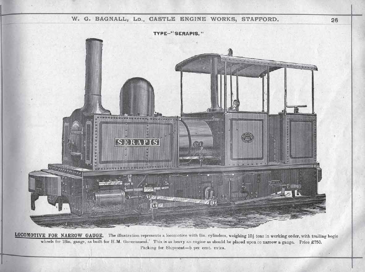
Although the use of an 18in-gauge railway at Suakin was later to spark heated debate on the suitability of the gauge, particularly for locomotive-hauled lines, in the Royal Engineers’ Journal, in 1885 at least, the RE authorities felt sufficiently confident to place orders for ten new locomotives intended for shipment to join the Suakin campaign. In the event, the locomotives were delivered in June–August 1885, too late for the campaign, and eventually passed to the RAR following a period of storage and, in some cases at least, use by the Royal Engineers at Chatham. Five of the locomotives were constructed by W.G. Bagnall & Co. of Stafford as Works Nos 710–4. The design of these 0-4-2 wing-and-back tank locomotives is illustrated by the accompanying engraving from which it is apparent that the buffer arrangements of the locomotives intended for Suakin would have needed to have been altered on the RAR as they were non-standard as built. Makers’ records show that OSIRIS was returned to Stafford for a major overhaul in 1894 indicating that it was the class member that received the most use by the Royal Engineers at Chatham. Unlike their Vulcan Foundry precursors, the shape of the rear mainframes on these Bagnalls was inconsistent with their being fitted with the ‘English’-pattern trailing truck and it would appear that they were fitted with the ordinary Bissell variety. Be that as it may, it was recorded in Leslie S. Robertson’s 1898 work that the trailing truck design proved to be less than satisfactory and that the locomotives were apt to derail in service. The fact that Britain’s military presence in Sudan from the 1880s onwards was ostensibly in alliance with Egypt was reflected in the choice of names of ancient Egyptian deities for these locomotives. (Maker’s catalogue)
The Fowler quintet was allocated Works Nos 5058–62 of 1885, were described by the makers as being ‘direct drive’ and supplied to the War Department. Direct drive refers to the obvious peculiarity of the design to any informed observer, namely the fact that the big end bearings did not act upon the rear crankpins but upon pins mounted in upward projections at the rear ends of the coupling rods. The purpose of this arrangement was that the big ends would have been kept safer from obstructions at rail level, a principle inherited from the Greig & Beadon system previously described. In order to preserve the lateral alignment of the connecting rods, the trailing portions of the coupling rods had to be realigned outwards from the customary position, thereby creating a ‘kink’ in the rods to allow space for the outside Stephenson/Howe link motion eccentrics. As to the locomotives’ other features, they were fitted with conventional side tanks equipped with recesses to accommodate the sandboxes, stovepipe chimneys (as with their Bagnall contemporaries), long round-topped fireboxes (as opposed to the wide Belpaire variety), English-pattern trailing trucks, integral equalized suspension for the coupled axles, and single slide bars (the latter as with the other 18in-gauge 0-4-2 designs for the Royal Engineers). The wheelbase was 3ft (coupled) and 7ft 6in in total.
As they were completed between June and August 1885, none of the ten 0-4-2Ts purpose-built for the Suakin-Berber Railway expedition are ever believed to have reached Suakin as the decision to abandon the undertaking had already been made. They are believed to have been delivered to the Royal Arsenal for initial storage prior to transfer to the Royal Engineers at Chatham, where they would probably have been kept at the Royal Engineers’ Park adjacent to Prince Frederick’s Bastion (as suggested by annotations to the recently-discovered drawing of Osiris). From there, during the next decade or so, they would have made occasional outings for training purposes onto the 18in-gauge tracks associated with the School of Military Engineering.

The remaining five 18in-gauge locomotives constructed for the Suakin campaign were, as political considerations dictated, supplied by another concern, in this case John Fowler & Co. The class is shown to advantage in this illustration of Cormorant (Works No. 5058 of 1885). Sadly, the maker’s plans for this class (which was built shortly before the incorporation of Fowlers as a limited company) do not survive, but it can be inferred from the pattern of rivets on the mainframes and from examination of the drawings of later Fowler locomotives that this class would have been fitted with the English-pattern trailing truck. The maker’s records stated that these locomotives were ‘direct drive’, at first apparently a statement of the obvious, but in reality a statement that requires some historical explanation. From 1880 onwards, Fowlers had constructed a design of locomotive to the 2-4-0 and 0-4-2 wheel arrangements, utilizing the Greig & Beadon patent for indirect jackshaft drive. The object of this arrangement, as with the 1879 Geoghegan patent for use on Guinness Brewery tramway locomotives from 1882 onwards, was to allow the cylinders and valve motion to be mounted higher up on the locomotive so as to avoid potential obstructions at ground level. In reality, the Greig & Beadon arrangement added to complication, construction and maintenance costs and proved clumsy to incorporate into a locomotive with cylinders of more than 5.5in diameter. From about 1883, therefore, Fowlers tried out a compromise arrangement that reverted to direct drive but utilized a ‘big end’ bearing set above and forward of the rear coupled crankpin. As can be seen from the accompanying photograph, it was this arrangement that was incorporated into the five locomotives intended for Suakin. The choice of names for the five Fowlers appears to have been influenced by naval practice of the period, as exemplified by the still-extant HMS Gannet now to be found at Chatham Historic Dockyard. In the event Gannet was not chosen as a name for one of the locomotives (although the ship was later to see service off Suakin), although it would make a fine choice should a replica of this, or more likely the next class, ever be constructed. (Maker’s photograph)
There were conflicting views expressed on the performances of Vulcan and Mercury at Suakin in the Royal Engineers Journal during 1885. In the July issue, Captain H.G. Kunhardt expressed the view that the engines were only capable of hauling 25 tons at a speed of 8 miles an hour and not worth considering for work other than in arsenals or dockyards. In the following issue, Captain W.W. Robinson put up a spirited defence of the 18in-gauge lines and pointed out the capabilities of the two little Vulcans on the Medway Fortifications system, claiming that each could manage a load of 60 tons, exclusive of tare load of rolling stock, at a speed of 15 miles an hour, or haul a net load of 13 tons of ballast over a line with a ruling gradient of 1 in 35. He also pointed out the performance of 18in-gauge locomotives at Woolwich when unloading the surplus Suakin equipment there, i.e. a train of 95 trucks loaded with 237 tons of rails being dragged a distance of 2.5 miles to Plumstead Marshes by a single locomotive. He did concede, however, that 2ft 6in gauge might be more appropriate for some applications where considerations of scale justified its use. Captain Kunhardt replied in the December issue, pointing out that at Suakin the engines ‘could be heard a mile off with their bones rattling’. He stated that while the engines could each manage four water tanks carried on two trucks (net weight 10 tons) at a reasonable speed, they struggled with an extra wagon carrying two further tanks (net total 15 tons). He went on to emphasize the difficulty that the locomotives had in coping with the harsh conditions in the field when compared with the landscape at Woolwich and Chatham, particularly the adverse effect of sand and grit in the bearings on such small locomotives as their motion was so close to ground level. His preference was for the Indian metre gauge originally envisaged for the Suakin-Berber Railway (as evidenced by a surviving document in The National Archives).
Captain Kunhardt’s comments appear to have received some support from the RE authorities, as demonstrated by two immediate consequences of experience at Suakin. The first of these was that support for the use of 2ft 6in-gauge lines gained some influential backers in addition to the already-convinced Lieutenant Colonel John Hogg RE, and the Chattenden & Upnor line was converted from standard gauge to dual-standard/2ft 6in gauge. Secondly, Vulcan and Mercury were not considered in sufficiently good condition to return to duties on the Fortifications system and they appear to have been sold for use in 1886 in experiments carried out at the Arsenal by Thomas Russell Crampton in support of his work on a ‘double single’ locomotive. In these experiments, one of the locomotives was left unaltered, while the other was described in the Proceedings of the Institution of Mechanical Engineers by Crampton as
a narrow gauge locomotive with four adhesion wheels running on regular work, having two equal cylinders on each side, of 6 inches diameter and 7 inches stroke, which worked in cranks opposite to each other, or 180 degrees apart; the two cranks were close to each other driving on the outside of the same wheel, one being an overhung, or return crank.
The unaltered engine was described as having 7in x 14in cylinders [author’s note: perhaps 12in was mistaken for 1ft 2in] and a boiler pressure of 145lb per square inch. It was further stated that ‘on testing each [locomotive] by itself without a train to ascertain the friction, the altered engine was found to start with 30 percent less power than the unaltered.’ Crampton patented a standard-gauge 2-2-2-2T based on the results of these experiments, although this incorporated a peculiar pattern of cylindrical firebox (see Chapter 2). Despite the proposal being published in Iron and presented to the British Association, as has been noted it appears to have been abortive with Vulcan and Mercury fading into obscurity shortly afterwards.
Although the pro-2ft 6in-gauge lobby had increased its support within the Royal Engineers, the 18in gauge was not dead yet and it was decided to replace Vulcan and Mercury with two further Fowler 0-4-2Ts, presumably leaving Mars and Venus gainfully employed on the Chatham Borstal system. These were delivered in December 1885 and differed from their five precursors in having a raised boiler pitch, conventional coupling rods and crankpins, lower-set cylinders with parallel axis valve drive and Joy’s valve gear. If one ignores the fact that they were built to the Royal Engineers’ restricted width limits, they were very much a pattern-setting design for many subsequent narrow-gauge tank locomotives made at the Steam Plough Works. They bore the Works Nos 5063–4 and were probably delivered directly to the Royal Engineers at Chatham. As with Works 5058-62 a slightly raised fire box wrapper was employed. Their arrival on the scene maintained the reserve strength of front-line 18in-gauge steam locomotives at a dozen (as suggested in a letter by a Mr P.M. Kalla-Bishop in August 1959’s edition of Railway Magazine), and they were the last purpose-designed locomotives of the gauge to be completed for this particular use. The previously-mentioned Renown proposal never saw the light of day while, as we have seen, the design of 1896-built Rameses was adapted from a metre gauge inside-framed class supplied for construction and maintenance work on Gibraltar Dockyard.
A letter dated 31 January 1896 from the Deputy Inspector of Fortifications to the president of the Royal Engineers Committee stated that the break of gauge on a siege railway between the local gauge and the 18in gauge should take place at the artillery depot or field arsenal, with any 18in-gauge lines forward of this point being of a portable nature, reliant on hand or animal motive power. This date would explain why Rameses was built as it would have been ordered some weeks before, but it would also be an indication of when the dozen-strong strategic reserve would have been transferred into Royal Arsenal Railways stock. The total narrow-gauge locomotive stock figure of thirty-seven mentioned in Leslie S. Robertson’s Narrow Gauge Railways – Two feet and Under paper of 1898 is clear proof of all the locomotives’ transfer by that date, as is his mention of the Bagnall 0-4-2T design but, rather strangely, there is no mention of the Fowlers by name. His emphasis on the shortcomings of the trailing trucks of the Bagnall 0-4-2Ts is further evidence that these were not of the ‘Major English’ pattern as the latter type of trailing truck was to make a further impact on RAR locomotive practice as will be seen later. The RAR system was thus destined to enter the Second Boer War with a complement of narrow-gauge locomotives over three dozen strong, of which almost one-third had been thrust upon it!

As mentioned in the text, two Fowler 0-4-2Ts were completed as afterthoughts for the Royal Engineers in December 1885 as Works Nos 5063–4. Unlike their five forerunners, these locomotives were equipped with the conventional arrangement of drive for an outside-cylinder locomotive and they were also fitted with Joy’s valve gear. This had been utilized in 1884 on the first of the Falcon-built Midge-class 0-4-2Ts (forerunners of the Kerr, Stuart Skylark class and subsequent developments) and its use set the pattern for many succeeding Fowler narrow-gauge locomotives (and also possibly for the famous Lynton & Barnstaple 2-6-2Ts constructed by the firm’s neighbours and rivals Manning Wardle from 1897 until 1925). An important point to note in the context of Fowler locomotive evolution generally is that the requirements of the Royal Engineers’ ‘Suakin’ loading gauge (limited to a width of approximately 5ft 5in) would have precluded the adaptation of the designs of Fowler Nos 5058–5064 to 2ft gauge without modification of the mainframe stretchers. Subsequent Fowler outside-framed steam locomotives of less than 2ft gauge were built with mainframes spaced sufficiently far apart for 2ft-gauge wheelsets and brake rigging to be substituted without the need for such modification to be undertaken. In more recent times, this has proved to be a major boon for those wishing to restore 50cm-gauge Fowler 0-4-2Ts repatriated from Mozambique, and one such locomotive has already been restored to working order on the 2ft-gauge Bredgar & Wormshill Railway in Kent. Another consequence of the combination of one-piece side mainframes and the tight loading gauge on Nos. 5063–4 was that a relatively long firebox had to be used, in conjunction with a sloping grate, in order to clear the leading stretcher for the English-pattern side control arrangement and the lower stretcher for the truck pivot. Major English’s close association with John Fowler & Co. is evidenced by the fact that the short 3ft coupled wheelbase found on his Vulcan Foundry locomotive design reappears on the Fowler specimens in preference to the 4ft dimension used on the Bagnalls. This would almost certainly have been one reason why the RAR appeared to have preferred the Fowlers to their Stafford contemporaries on the sharp curves of much of the RAR system. The naming policy adopted for the first five Fowlers was perpetuated for this final pair: they became Owl and Pelican, although surviving records do not indicate which of the pair was which. (Maker’s photograph)
As a prototype, Hornsby No. 1705 Lachesis obviously impressed the RAR authorities sufficiently for further locomotives operating on the same principle to be ordered from the same manufacturer. It seems obvious, however, that the engine’s comparative lack of power in relation to a steam locomotive of similar size proved a drawback from its early days of operation (as would have been its relative difficulty of starting), and as early as 1900 Hornsbys proposed a design for a more powerful 18in-gauge 0-4-0 utilizing a ‘rolling chassis’ of similar configuration to Lachesis but now incorporating the characteristic ‘home-grown’ cab in place of the Manning Wardle canopy. This proposal was covered by Hornsby Drawing No. 16625 and appears to have been influenced by the fact that Hornsbys patented a two-cylinder engine in 1900 (Patent No. 5770). The arrangement depicted in Drawing No. 16625 was not a simple two-cylinder one at all, but a ‘Siamese cylinder’ in which two pistons working at 180 degrees to one another ran in longitudinal bores offset by a sufficient amount to allow the use of a conventional two-throw crankshaft. The right-hand piston drove its connecting rod (which emerged from the leading end of the cylinder block) in the normal fashion, whereas the left-hand one drove onto a crosshead at the rear end of the cylinder block, transmitting its motion forward to its connecting rod by means of slides and another crosshead. The two offset cylinder bores were connected by a ‘skew’ passage and shared a single vaporizer and oil pump. One design improvement that would have been incorporated into this locomotive is immediately apparent, i.e. the change in vertical section of the cooling tower body from circular to the use of central leading and trailing flat surfaces. This allowed for the use of eight perforated cooling header pipes instead of the six used on Lachesis. The design projected in Drawing No. 16625 never became a reality but, as we shall see, it was to influence subsequent events. The next surviving (and ultimately defining) proposal was contained in Drawing No. 16632. This reverted to the basic type of oil engine used on Lachesis, but lengthened the chassis at the leading end to produce a 2-4-0. The main reason for this modification appears to have been the provision of more substantial staying of the chassis at the leading end. It would also have offered the possibility of smoother riding and improved weight distribution, but at the expense of a more unwieldy locomotive. This latter observation is particularly pertinent in light of the fact that the original 3ft 6in coupled wheelbase of Lachesis was augmented by the 5ft forward extension to produce a new total figure of 8ft 6in. The cooling tower modification proposed in Drawing No. 16625 was incorporated into this and the other proposals for the design of the next three Hornsby locomotives for the RAR. The previous use of locomotives of the 0-4-2 wheel arrangement at the Arsenal was noted by Hornsbys and a suitable alternative proposal appeared under Drawing No. 16633, but it proved to be abortive, in all probability because it would have suffered from similar front-end lateral staying difficulties to Lachesis.
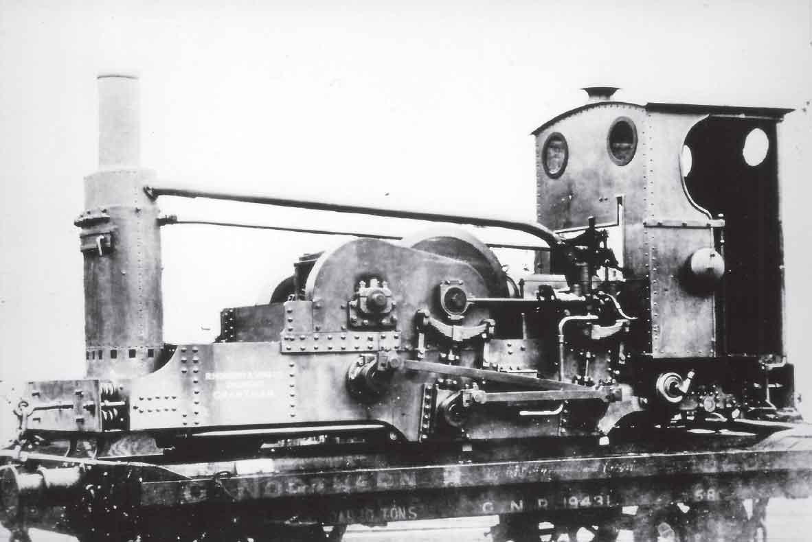
This left-hand three-quarter view of Clotho (Hornsby No. 4535 of 1900) shows to advantage the modifications to the basic design of the ‘ordinary’ Hornsby Akroyd locomotives made in the light of experience with Lachesis. At least three further design proposals were made before the basic design of Clotho was arrived at with Drawing No. 16633 and even this latter drawing was subject to refinement (Drawing No. 16651). It is clear that the front end configuration of Lachesis, in which the design of the frame stretchers was rather compromised by the location of the transmission gearing, was found to be wanting, as was the locomotive’s weight distribution (affected by the position of the transmission gearing and the cooling tower). These difficulties could only be addressed by adopting a 2-4-0 wheel arrangement, thereby lengthening the locomotive’s wheelbase by 5ft. Other details apparent in this view are (from front to back) the cooling tower with its redesigned shape, the safety guards for the transmission gearing (of different design to those fitted to Lachesis), the jackshaft drive, the leading axlebox and suspension, the left-hand flywheel and water circulation pump eccentric and body, the rear axlebox and suspension with (above) the hand-worked air pump to replenish the air reservoir (used for starting the engine), the cab area with externally-mounted crank handle and primary gear for the lamp fan, and (below footplate) the fan blade housing. The lever for working the hand pump is missing from this view, but its working recess can be seen in the spectacle plate. (Maker’s photograph)
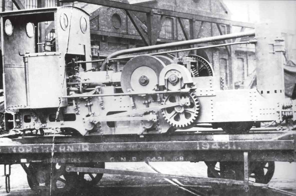
The right-hand side of Clotho is shown in this view. Although the extended mainframes (probably by this stage made in-house at Grantham but still betraying their Manning Wardle design influence at the rear end) are very much in evidence and certain sundry design alterations have been made, such as to the governor for the fuel oil pump, much of the locomotive’s design is still the same as that for Lachesis. The asymmetrical nature of the cab is very apparent, as are the guards for the transmission gearing which were not fitted for the works photograph of Lachesis. Part of the pony truck can be seen below the leading section of the mainframe, namely the wheelset, flanked fore-and-aft by the bearings for the English-pattern ‘vertical crankshaft’ side control arrangement, with part of the truck’s A-frame being visible immediately behind the trailing bearing. Despite the proud manufacturer’s ‘credit’ stencils on the mainframes in the pony truck’s vicinity, much of Clotho’s running gear consisted of items designed by two Leeds makers and some of which was constructed by one of them. (Maker’s photograph)

Above and below: These right-hand side and rear elevation drawings of Clotho have been prepared from photographic evidence and Richard Hornsby Drawings 16632 and 16651. They show the working details of the locomotive, including the bearings for the jackshaft and coupling rods (omitted from the drawing of Lachesis for reasons of clarity) and the pony truck. The guard for the extreme right-hand speed gear and the cylinder lubricator are shown in exploded view and the final drive belt for the vaporizer lamp fan is omitted from the rear view, again for reasons of clarity. (Author)
The left-hand side and rear elevation views of Clotho show important external details, such as the redesigned guards for the transmission gearing (as compared with Lachesis), cooling water circulation system, fan for the vaporizer lamp (with handle mounted externally rather than internally as on Lachesis) and air pump for the starting mechanism. The cab backplate is shown in the lower middle view. The first of the additional detail views (e) shows the front end staying arrangement, by which means the ends of the girders that formed the engine bed were secured to the frame stretcher that carried the main pony truck pivot. The design of the pony truck, based on the trailing truck used on the John Fowler 0-4-2Ts (it is even possible to show that the latter would have had the same 3ft radius of swing), can be seen to advantage in these views. The final detail view shows the leading and trailing drawbar stretchers, the latter being of similar design to that found on Lachesis. (Author)

In the end, therefore, the design of the next three Hornsby locomotives was based on Drawing No. 16632 and an updated variant with small sundry detail differences, No. 16651. The three 9½hp 2-4-0 locomotives were Maker’s Nos 4535 Clotho, 5242 Atropos and 5883 Hecate. Their respective delivery dates were 11 May 1900, 15 May 1901 and 11 March 1902. The general mechanical design of these three locomotives in respect of the engine, transmission, coupled wheelsets, axleboxes and motion components was similar to Lachesis, but a number of small detail improvements were made, all covered by drawings numbered in the 16000 series. The cab (upon which was mounted a fan handle now moved to outside footplate limits) was now made in-house and the same was almost certainly true of the mainframes. While the suspension, coupled wheelsets and motion of Nos 4535, 5242 and 5883 probably remained Manning Wardle products, Drawing No. 14453 was further endorsed ‘Red Dimensions as per letter dated 5th Sep 00 from J. Fowler & Co.’ with respect to the limited amount of machining carried out on the wheel centres. This would appear to have resulted from the drawings for a coupled wheelset being ‘borrowed’ by Fowlers in order for this well-known Leeds concern to manufacture the wheels for the pony trucks. These trucks, for which the component drawing survives, were certainly Fowler products as evidenced by their design (identical to the abortive patent of Major Thomas English used on many John Fowler narrow-gauge locomotives including the RAR specimens) and the fact that a Fowler drawing survives for the slightly modified example used on the 15hp 2-4-0 Alecto completed in 1904. Although all the early Hornsby locomotives suffered from the difficulties that were to be expected of such experimental creations, and as well as being underpowered they were also considered to be noisy in operation and difficult to start, their careers were of sufficient duration for them to be regarded as the first commercially successful internal combustion locomotives in service on British soil. With their introduction, therefore, the Royal Arsenal Railways had achieved another important historical distinction.
The final piece of the jigsaw concerning the transfer of Royal Engineers’ front-line locomotives to the RAR concerns the Medway Fortifications system. Although it continued to be shown on maps well into the twentieth century, this line is believed to have fallen out of use at the very end of the nineteenth century. At the time of its closure, its locomotive stock would have consisted of the two Vulcan back tanks, Mars and Venus, along with as many of the Handyside locomotives that remained in service at the time. The survival of an undated photograph of a Handyside (minus its winding gear, gripping struts and leading pony truck) at work in the Arsenal is a clear indication that the Fortifications line locomotive stock found its way to the Arsenal for temporary employment during the Second Boer War of 1899–1902. Other photographs of Mars taken during the locomotive’s employment at Longmoor after 1905 support this assertion as they show that the engine’s buffers had been extended upwards so as to match RAR stock (although this may have happened at Chatham as some Royal Engineers’ rolling stock, along with the Handysides, had buffers of RAR pattern). With the arrival of new steam locomotives in 1901–02, it is thought that the career of any surviving Handysides would have been a short one, while the Vulcan back tanks are known to have ended their working lives at Longmoor after transfer there in 1905.
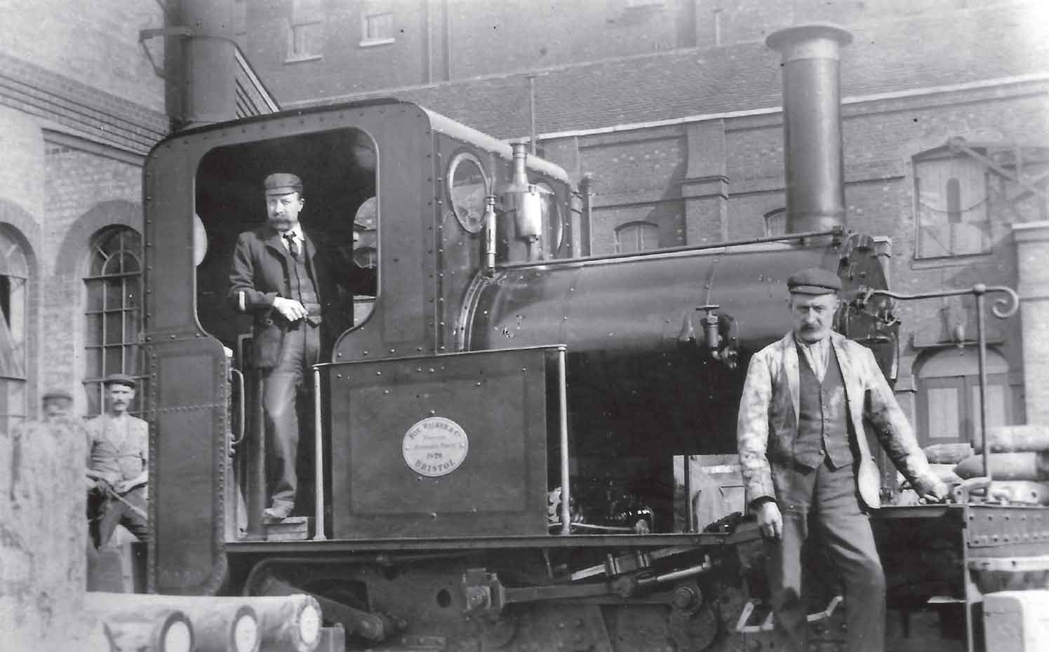
At least one of the Handysides was shorn of its gripping equipment, winch and leading pony truck and transferred to the RAR following its being declared redundant from work on the Chatham Eastern Defences (Borstal) Railway, where the class was used following its rejection from frontline service. This photograph shows the locomotive surrounded by munitions at a date almost certainly after 1898 when figures for narrow-gauge locomotive numbers given in Leslie S. Robertson’s book do not suggest the engine’s presence in RAR stock. The engine would appear to have been modified and transferred to the Arsenal around the outbreak of the Second Boer War of 1899–1902 as a stopgap measure prior to the purchase of new locomotives. Sadly it is not possible to decipher the worksplate in order to ascertain the locomotive’s identity, nor is it currently possible to ascertain just how many of the Handysides were so treated, nor their final date of demise (although this must have been prior to 1907). For further consequences of the cessation of use of 18in-gauge steam locomotives on the Borstal system, see the later caption referring to the locomotives Mars and Venus. (R.W. Kidner)
The next class of 18in-gauge steam locomotive to make its appearance on the Royal Arsenal Railways emanated from Kerr, Stuart & Co. Ltd of the California Works, Stoke-on-Trent. Having had the Royal Engineers’ strategic reserve of 0-4-2 tank locomotives forced upon them by events outside their control with, in all probability, the two additional locomotives of this type from the Medway system, the operational staff would no doubt have been relieved to receive purpose-built locomotives into stock once more. The new class reverted to the tried-and-trusted formula of a simple 0-4-0ST wheel arrangement with the customary chassis and boiler configuration. The general styling of the class, with its domeless boiler with raised firebox wrapper, inside link motion actuating outside valves via rocker shafts, simple part-circular section tank and elongated D-section smokebox, fitted in with the trends exhibited by several of the maker’s other products, while the commodious cab was very reminiscent of the company’s Skylark class. Where wheels, cylinders and wheelbase were concerned, the dimensions of the Pluto class were on a par with those of the narrow-gauge Hudswell locomotives, although they were half a ton heavier and over 4 inches wider. During the Second Boer War, six members of the class (Works Nos 761–3 of 1901 and 807–9 of 1902) were supplied. The maker’s drawings list reveals that some slight modifications were made to the design between the construction of the two batches, i.e. to the wheelsets, regulator, whistle, spectacle rims and safety valves. When compared with the earlier four-wheeled narrow-gauge classes, these six Kerr, Stuart products were somewhat ‘broad in the beam’, coming out at 5ft 4in wide overall, restricting their use in certain shop environments. The reason for this feature is betrayed by close inspection of the maker’s plans, which show that the mountings for the ‘composite’ buffers were rigid, and the Royal Arsenal Rules and Regulations for 1902 which refer to ‘narrow gauge engines used for passenger trains’. While it seems certain that the Bagnall and Fowler 0-4-2Ts were also used for passenger work, owing to their longer overall wheelbases and width dimension in excess of 5ft 4in, the Pluto class appeared to have been the preferred choice of their period for passenger work. Surviving photographic evidence of the time appears to bear this out.
Richard Hornsby & Sons did not give up on the idea of producing a more powerful version of its oil-engined locomotive and, in 1903, a 2ft 6in-gauge rod-coupled 0-6-6-0 20hp locomotive was constructed for the Royal Engineers on the Chattenden & Upnor Railway. This locomotive was rather more complex than Lachesis and Clotho in concept, its engine reverting to the ‘double piston’ principle envisaged in Drawing No. 16625, but this time being of the true opposed piston variety with a single-cylinder bore. As in Drawing No. 16625 there was one single vaporizer, this time feeding the single cylinder halfway along its length and the arrangement of connecting rods was similar to that envisaged in the earlier drawing, with the rearmost one being directly driven by the leading piston and the leading connecting rod being driven (via the ‘double crosshead and slide’ arrangement) by the rearmost piston. In contrast to the arrangement used by the earlier Hornsby locomotives, the 2ft 6in-gauge specimen was fitted with a fan-cooled cylindrical radiator in place of the cooling tower, while the final drive was by means of universally jointed shafts and bevel gearing. The locomotive, which was given the Works No. 6234, was not regarded as a success by the Royal Engineers as the engine was prone to overheating and the transmission absorbed rather too much of the locomotive’s power. Nonetheless, a 15hp 2-4-0 locomotive employing the same opposed piston principles, but reverting to the basic chassis and cooling principles of Clotho was constructed for the RAR in 1904 as Works No. 7226 Alecto. The cylinder was 9.75in bore with 10in stroke for each piston and the engine was rated at 350 revolutions per minute. The locomotive was geared for normal working at 8 miles per hour (fast) and 5 miles per hour (slow). It was immediately set to work in the Danger Buildings area with its precursors.
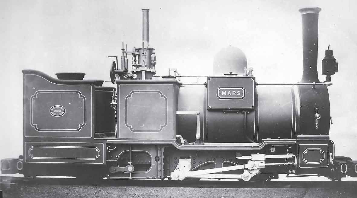
The Second Boer War of 1899–1902 caused an upsurge in activity at the Arsenal at a time when the Royal Engineers’ two favoured locomotives formerly in use on the Medway Fortifications line had become surplus to requirements after that system had fallen into disuse. Vulcan Foundry 0-4-2 well-and-back tank locomotives Mars and Venus (respectively Works Nos 1160 and 1161) had been supplied to the Fortifications system in 1885 as replacements for Vulcan and Mercury when the latter were shipped to Suakin. These locomotives were constructed to a similar design to the earlier pair, although they differed in that they had horizontal rather than sloping foundation rings. It can be deduced from photographic evidence that Mars and Venus were transferred to Woolwich after their spell at Chatham as the buffers of Mars at least were modified so as to be compatible with the RAR pattern. As is well known, these locomotives were both transferred to Longmoor, Hampshire, in 1905. (Maker’s photograph)

Phaeton (Kerr, Stuart 763 of 1901) is shown here in ‘works grey’ prior to delivery to the Arsenal. The aesthetic properties of this attractive 0-4-0ST design were very much in line with the company’s standard products, such as the Sirdar, Skylark and (later) the Tattoo classes. (Maker’s photograph)
Following the entry of Alecto into service, there were no new 18in-gauge locomotive acquisitions for nearly a decade, but the locomotive repair shop was kept well-occupied during this period with keeping the existing fleet in service and making various modifications to maintain fitness for service. Wooden ‘infilling’ of the cabs became evident on some members at least of the ‘Royal Engineers’ 0-4-2T’ grouping (although not Flamingo at the time of its departure with Mars and Venus to Longmoor in 1905). Such evidence as exists indicates that this modification occurred c.1906 and that the two Fowlers in the photograph showing the locomotive shed had virtually new cab planking at this stage. The Bagnall 0-4-2Ts, partly for reasons already recorded, appear not to have been as well-regarded as the Fowlers and the first withdrawal of a class member from service, Isis, had certainly occurred prior to April 1911 as we have seen. Their longer wheelbase would have been another source of difficulty and this would have restricted their usefulness on the RAR. The Manning Wardle 0-4-0STs underwent a considerable amount of ‘butchery’ to keep them in service, with Coehorn as illustrated having received a boiler and smokebox assembly of different design to the original prior to 1911, as evidenced by its 120psi working boiler pressure rating mentioned in the Mechanical Engineering Department Report for the First World War period (this would have been correct as of 4 August 1914). Lord Raglan and Trumpeter were similarly classified, indicating that their final boilers also probably dated from the Edwardian period, but conclusive evidence has not come to light at the time of writing to show whether Coehorn’s altered design of boiler was adopted on any other class member or whether it was to remain unique. With its high pitch, it certainly did not do anything for the locomotive’s appearance or, in all probability, its riding characteristics!
A surviving photograph of John Fowler 0-4-2T Owl dating from the first decade of the twentieth century shows that its original Joy’s valve gear had been replaced by new gear of Walschaerts pattern. Sadly no corresponding photograph of the sister locomotive Pelican has yet come to light, but the appearance of Walschaerts’ valve gear in RAR 18in-gauge locomotive practice was to have a lasting effect as will be seen later.
In 1911, as evidenced by a subsequent sale advertisement, four of the Manning Wardle 0-4-0STs were reconstructed to constitute a new standard specification. New boilers were fitted, incorporating Ramsbottom safety valves (in place of the previously-used Salter pattern), a redesigned smokebox in which a single door opened downwards and, in all probability, the ‘Neath’ pattern spark arrester. The cab design was improved so that the locomotives were effectively renewed above running board level. The four locomotives initially selected for the reconstruction process were Boxer (the former Victoria that had been renamed, presumably in 1901), Shrapnel, Vauban and Arquebus. Shortly afterwards, during the first quarter of 1912, Serapis fell to the breakers, leaving only three of the Bagnall 0-4-2Ts in service at that stage. Despite initial teething problems with the rear-axle springing, the six Kerr, Stuart locomotives had proved successful in service, but their overall width dimension restricted their scope for use in the older shops in particular. Three more locomotives – Pompey, Brutus and Regulus – were purchased new from the same maker in August 1912. While outwardly similar to the 1901–02 products and employing the same drawings for the cylinders, much of the valve gear and other sundry components, new drawings were made for many parts of these locomotives, including the boiler, wheels and mainframes. This process was necessitated by the reduction in overall width of the engine, which could only be accomplished by reducing the frame spacing (with its attendant knock-on effects for the design of the boiler, frames, axleboxes, axles and other components). Although apparently regarded by the Mechanical Engineering Department as a simple continuation of the first six Kerr, Stuarts, Pompey and her sisters at the very least constituted a new subclass, if not a new class of locomotive.
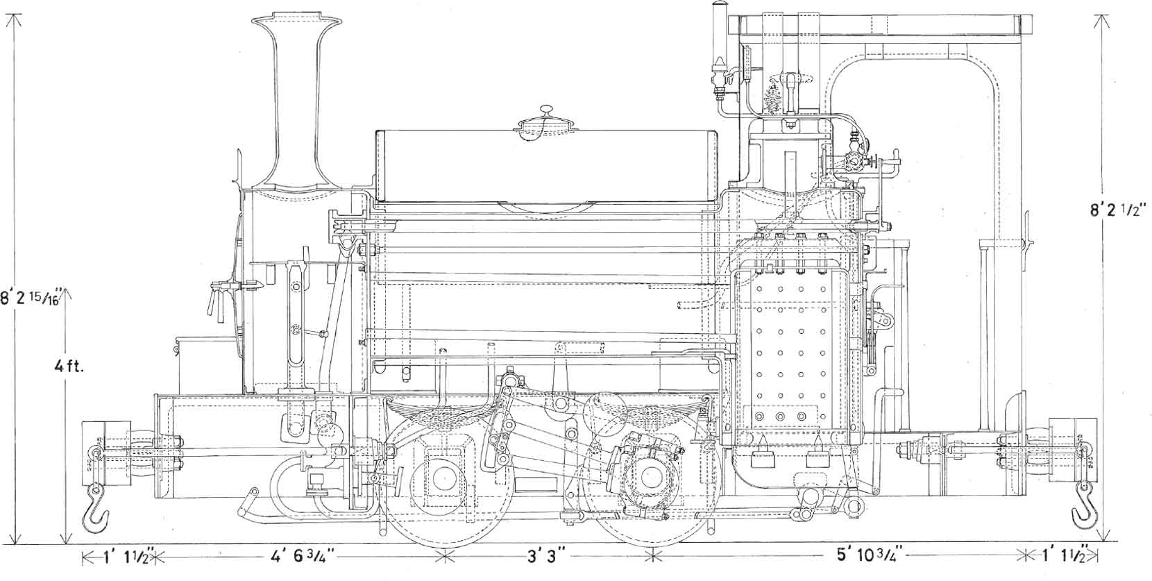
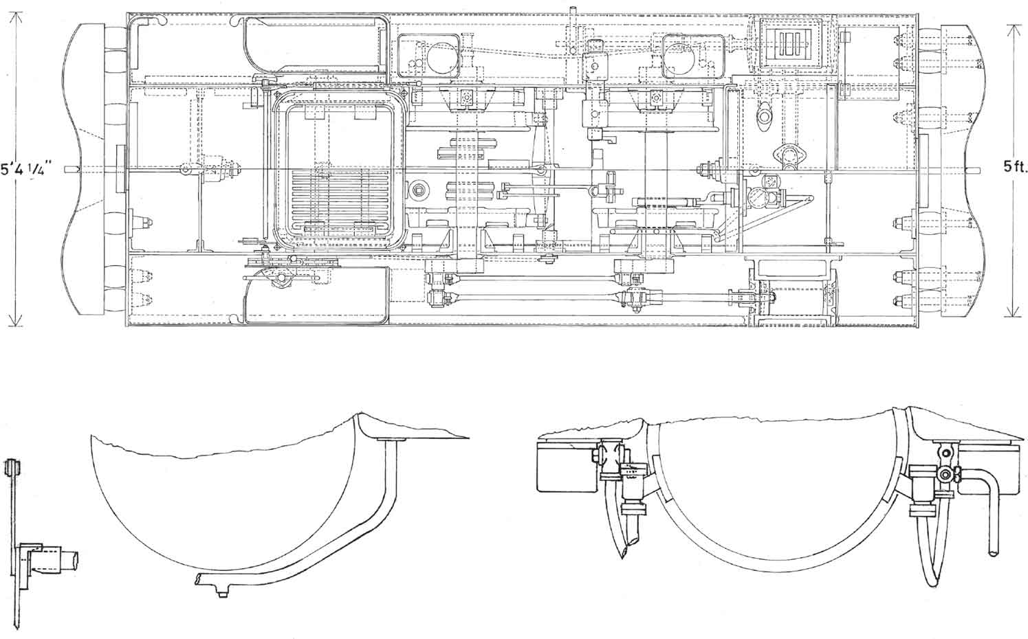

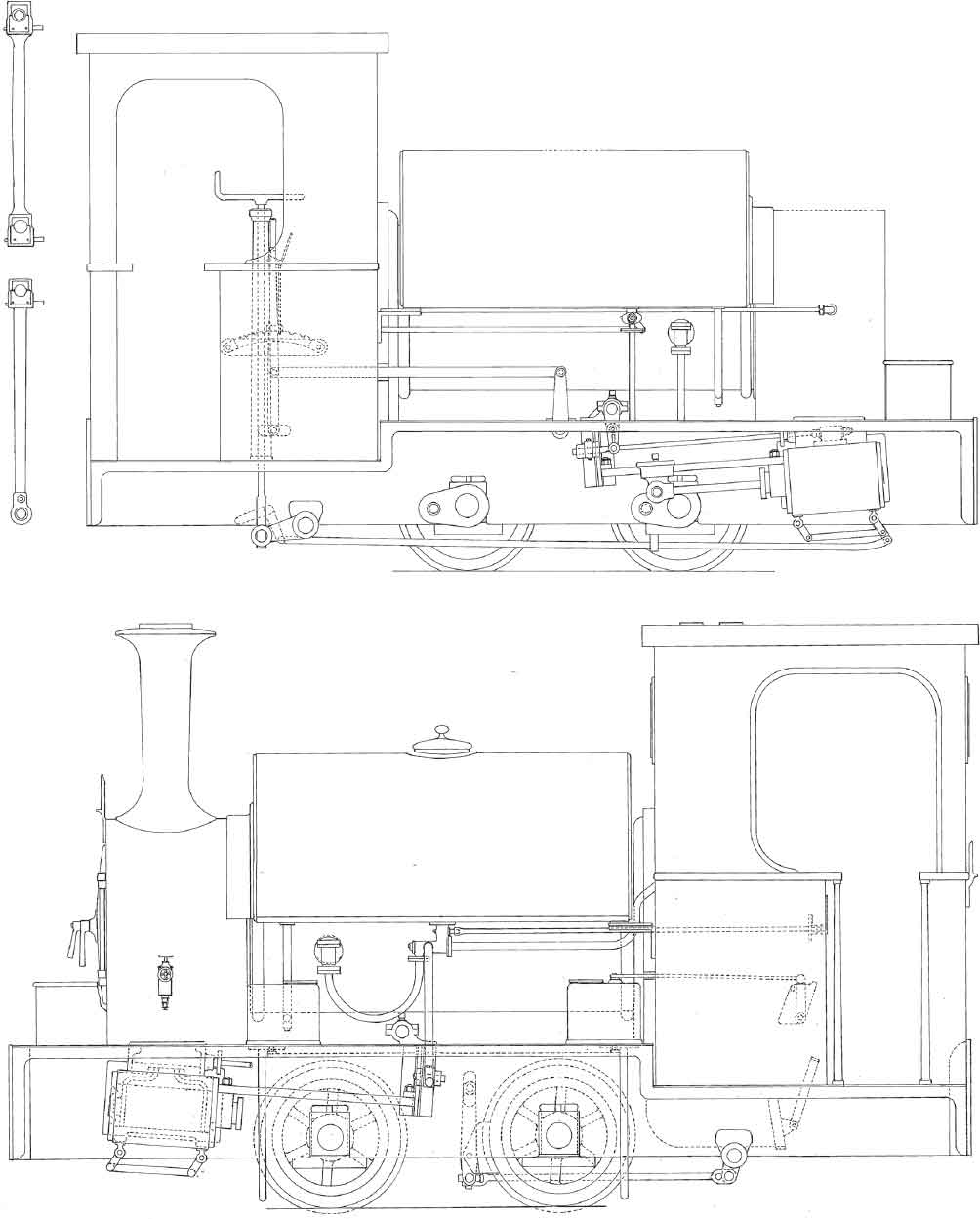
Drawings of the Pluto class are reproduced here. The sectional view shows that the specification, although produced for the RAR’s requirements, had much in common with other Kerr, Stuart designs, notably the Sirdar and Skylark classes, while the semi-circular section saddle tank in place of side tanks looked forward to the Tattoo and early forms of the Darwin and Brazil classes. The boiler, with its raised wrapper and back dome, was a typical maker’s arrangement, as was the straight-sided smokebox. It was of greater diameter and had a significantly greater heating surface than the Tattoo class (which had the same size cylinders), further supporting the view that the Pluto class was designed for the greater sustained demands associated with passenger work. Other features to note are the ‘inside to outside’ valve motion transmitted by rocker shafts via an external bellcrank incorporating vertical play for the valve spindle bearing (so as to convert arc motion to linear motion, an arrangement that harked back very much to the Sirdar and Skylark classes), the ‘T’-section spokes, the feedpump driven by an eccentric on the leading axle rather than the trailing one (as on the Manning Wardle and Hudswell Clarke 18in-gauge classes), the smokebox-mounted regulator and the rigidly-mounted buffers. The plan view shows how all the mechanical details were accommodated within the chassis area, emphasizing in particular the relative positions of the eccentrics and steamchests. The other views show the reverser bellcrank and ‘clack’ valve details, and further detailed elevations of the front, rear and both sides of the locomotive. (Author)
There were no acquisitions or disposals in the narrow-gauge locomotive sphere during the year ending 31 March 1914, but it is known that four more of the Manning Wardle 0-4-0STs – Albert Edward, Gordon, Fusee and Torpedo – were dealt with in similar fashion to the 1911 rebuilds at some stage during 1914, although it is not known whether this was before or after the accounting year end. Rocket and Norman Ramsey were adjudged to be unfit for further service and their scrapping was authorized in June 1914. Despite the company’s lack of success in obtaining an order for a new steam locomotive for the Arsenal after unification of the railway system and a spares order after 1913, it appears that Manning Wardle did not give up trying at the latter stage, for the scrapping of Rocket and Norman Ramsey is mentioned in the Manning Wardle records. October 1914 also saw the appearance of two more locomotives designed for operation within the Danger Buildings areas. With the nation now at war, more reliable motive power in this department had become a major priority and internal combustion technology was resorted to once again for the first of the locomotives to arrive. This was Megaera, a 40hp four-cylinder petrol-mechanical locomotive originally constructed to 20in gauge c.1911 by McEwan-Pratt & Co. of Wickford in Essex and altered by Baguley Cars Ltd of Burton-upon-Trent, Staffordshire (who had taken over the Wickford concern) in line with RAR requirements. The second arrival was Petrolea, the tenth and last Kerr, Stuart 0-4-0ST to see service on the 18in-gauge part of the RAR system. This locomotive was built to the same basic design as Pompey but differed from the latter in being oil-fired. Its introduction into the system had been agreed to by the CSOF and the superintendent of the RL with great misgivings and a considerable amount of persuasion on the part of Chief Mechanical Engineer Henry Roberts. While most of the drawings prepared for the production of Pompey were re-used, new drawings had to be made for the Kermode burner and its attendant piping, a drip tray (to prevent oil spillage), and modifications to the steam piping arrangements, cab design and rear drawgear necessitated by the adoption of the new fuel. Despite the initial misgivings, Petrolea proved to be satisfactory in service, resulting in the wider adoption of oil-fired steam locomotives for Danger Buildings work and staving off the day when internal combustion motive power would supplant steam on the RAR once and for all.
The loss of Iron Duke following its authorization for disposal in March 1915 was not greatly felt as it was regarded as worn out and was, in any case, non-standard. Following scrapping of most of the locomotive, its boiler was noted as being ‘reserved for other services’. The onset of conflict had nonetheless created the need for more 18in-gauge locomotives and, on 20 January 1915, an order was placed for five new machines from Hudswell Clarke. These were delivered in June and were, as with the Leeds manufacturer’s nineteenth-century products for the Arsenal’s 18in-gauge network, 0-4-0 saddle tanks with 7in x 12in cylinders and 3ft 3in wheelbase. Close examination of the manufacturer’s Drawings Register reveals that most of the chassis and running gear was built to the same drawings as those used for Basilisk, while the boiler and tank were built in accordance with standards more appropriate to their date of construction. In this connection, it is significant to note that whereas Carronade possessed thirty-six boiler tubes when new, this number had increased to forty-six for Carnarvon and her four sisters. Unfortunately for Hudswell Clarke’s reputation with the Arsenal’s authorities, the story of these locomotives is well-documented in the 1914–18 Mechanical Engineering Department Report, which stated:
the five N.G. locomotives purchased from Messrs. Hudswell Clarke in 1915 viz:- LONDON, KENT, CARNARVON, CORNWALL and ESSEX were found shortly after delivery to develop many defects due to faulty material, indifferent workmanship, and bad design and this question was taken up very strongly at the time with the Makers who subsequently replaced certain inferior fittings, and also made an allowance from the contract price in lieu of replacing tyres which were soft and rapidly wearing down. Other defects developed at a later stage after the engines had been in service [for] a few months, which were either due to faulty material or bad workmanship, but although the makers were again communicated with, no satisfaction could be obtained from them.
It is clear from this observation, therefore, that Hudswell Clarke appear to have been rather too eager initially to cut corners in order to obtain the contract to build these locomotives and the effect of this decision would have been particularly noticeable at a time when good-quality raw materials for manufacturing purposes were becoming increasingly scarce owing to the relatively recent onset of war. Nonetheless, given the difficulty experienced by the RAR in obtaining locomotives under the conditions prevalent at the time, there was nothing that could be done, save to make the best of a bad job and undertake the repairs and adjustments necessary to ensure that these five troublesome units performed the duties for which they were ordered.
The shortcomings of the Hornsby-Akroyd locomotives were also well-documented in the 1914–18 MED report where they were described as inefficient, low in tractive effort, slow in speed and difficult to start up (the reservoirs for the compressed air starting apparatus requiring lever operated hand pumps for their priming). Nonetheless, up to the outbreak of war, they had not only handled all the 18in-gauge Danger Buildings locomotive-worked traffic, but all the associated standard-gauge traffic as well (by means of the use of ‘divider’ trucks). The delays associated with starting up these locomotives at the main loco shed were aggravated by the fact that the Danger Buildings were located a mile or so distant from the shed. In order to dispense with the additional waste of time imposed by this inconvenience, a small locomotive shed was requested in 1913 to be located close to the Danger Buildings and this was provided in 1915. The 1920 map of the Arsenal does not indicate this building by name but the close proximity of Building E8A to the rolling stock repair sheds (E8), the fact that it contained only 18in-gauge track, the fact that it was still at that stage under MED jurisdiction, and the close proximity of an oil tank all suggest that this building began life as the Hornsby locomotive shed.
Some five days prior to the placing of the order for the five Hudswell Clarke 0-4-0STs (all of which were coal-fired and intended primarily for mainstream ‘shop’ work), an order was placed with the Bristol-based Avonside Engine Co. for four powerful oil-fired 0-4-0 tank locomotives. These were fitted with 8.5in x 12in cylinders, a dimension popular with this manufacturer that was exceeded on only two British-built 18in-gauge classes. These were four Bagnall 0-4-2WTs for the Kimberley Diamond Mines in South Africa with 12in x 15in cylinders (Works Nos 1814–1817; two surviving in preservation) and three Manning Wardle 0-4-0ST 9in x 12in Sunbeam-class locomotives for Chatham Dockyard (Maker’s Nos 1614, 1634 and 1808). It may be that Manning Wardle offered a modification of the Sunbeam class (adapted for oil-burning and with suitably redesigned drawgear) for use on the RAR (learning the fate of Rocket and Norman Ramsey in the process), but could not persuade the Arsenal authorities to accept the design on account of its low water tank capacity of 100 gallons. Be all of this as it may, the new Avonside design was a major departure from what had been ordered purposely for the Arsenal’s previous 18in-gauge requirements. Whereas the Manning Wardle, Hudswell Clarke and Kerr, Stuart designs, along with RCD No.3/Iron Duke and Ajax, had all been constructed with foundation rings sitting between the mainframes, the foundation rings on the four Avonsides sat slightly above the top of the frames. This design alteration resulted in a higher-pitched boiler and the need to adopt side tanks in place of the saddle tank that had been the order of the day for most of the RAR 18in-gauge ‘four-wheelers’ for over four decades. The use of side tanks enabled a water capacity of 260 gallons to be accommodated, while 50 gallons of oil fuel was contained in a pair of tanks, one located at the rear of each water tank and contained within the cab area. As was the overwhelming norm on the RAR’s 18in-gauge network, the new class employed outside mainframes, while the coupled wheel diameter of 2ft 1in was inherited from Carronade and her sisters. The aesthetic characteristics of the new class above running-board level followed the maker’s normal pattern (see, for instance, 1904-built Ascension No. 1 of the 2ft 6in-gauge Hoo Ness Naval tramway and the 2ft-gauge 0-4-0Ts built for South Africa’s Sezela Estates from 1915 onwards), and the ‘balloon’-pattern spark arrester was in keeping with this pattern. The 4ft 6in wheelbase that had been the order of the day for these locomotives was of no use on the RAR and this dimension was shortened to the Arsenal’s standard of 3ft 3in for the new class. Below running-board level there was to be another major departure from what had hitherto been normal Avonside practice for narrow-gauge designs. The rebuilding of Owl (and possibly Pelican in similar fashion) appeared to have impressed the MED sufficiently to request the incorporation of Walschaerts’ valve gear into the new locomotives in place of the link motion and rocker shaft arrangement that Avonside would otherwise have used. In order to accommodate the weighshaft, which sat above running-board level, small recesses were let in to the lower part of each side tank. As had been the case with Petrolea, the Kermode pattern of oil-burner was used. The new locomotives were delivered in July and August 1915, commencing with Bristol which arrived on the first day of the former month.
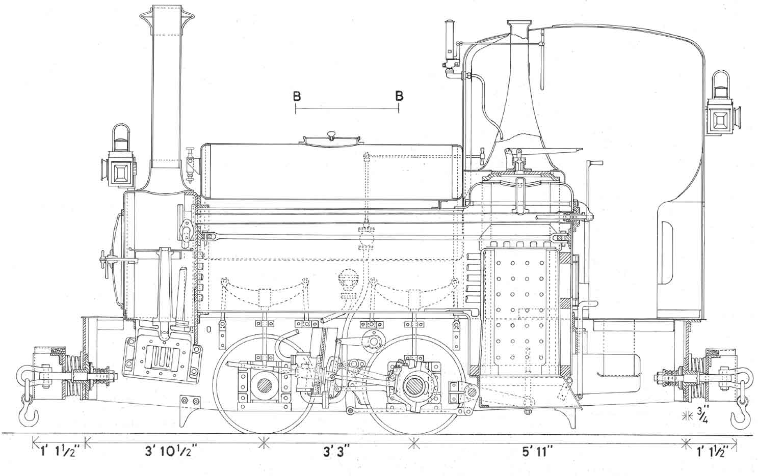
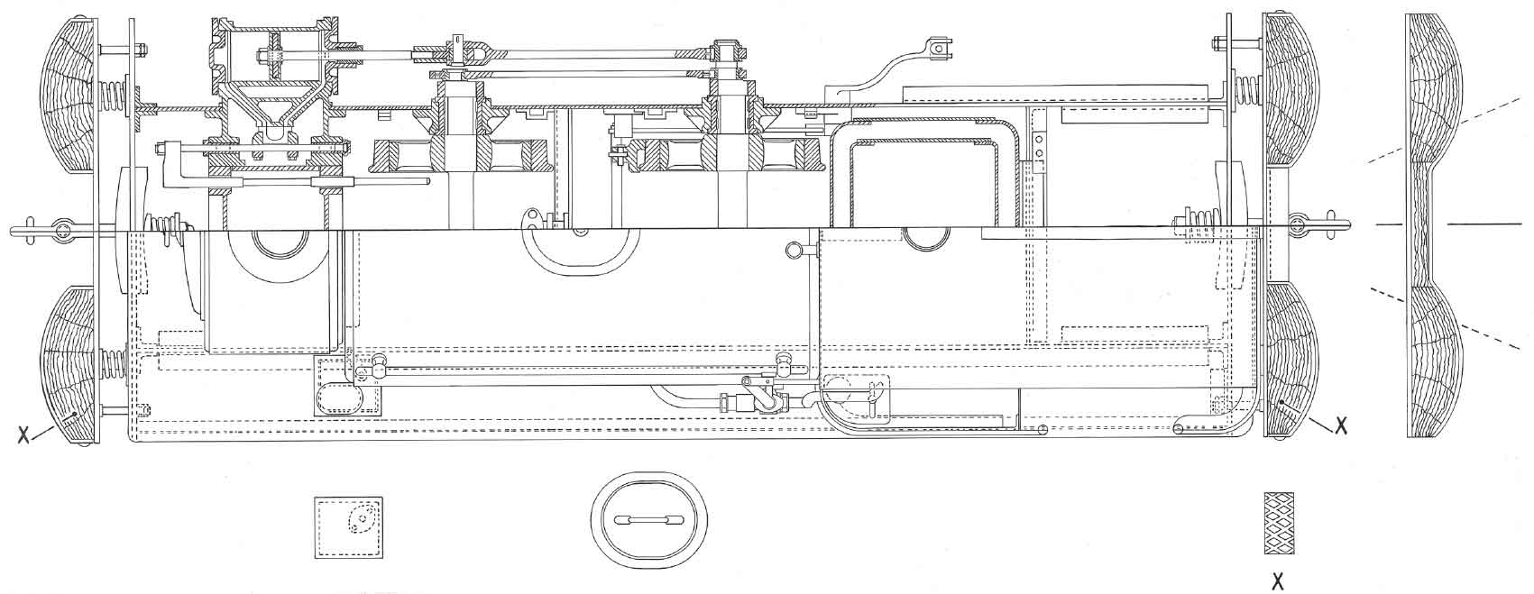
Above and below: The final five Hudswell Clarke 0-4-0STs for the 18in-gauge system were ordered in January 1915 and delivered during the following June. These drawings show this ill-fated batch of locomotives as originally built. The first and second drawings show respectively sectional side and plan views, while the fourth and fifth respectively are the front elevation and backhead diagrams and the third shows the feedpump stretcher. The boiler redesign, increasing the number of tubes from thirty-six (found on the 1880s-built precursors of the class) to forty-six, was clearly intended to increase heating surface and boiler efficiency. This feature and other redesigned details failed to impress the MED, and these five locomotives remained unpopular throughout their short career at Woolwich. (Author)

As has been mentioned in Chapter Four, two narrow-gauge steam locomotives were ordered during the latter part of 1915 by the superintendent of building works for use during the construction of new building work in the eastern part of the Arsenal, apparently in connection with CF No. 6 and QFCF No. 4. For reasons that do not seem apparent from surviving evidence they were constructed to 2ft rather than 18in gauge, since they appear to have been no more powerful than the majority of RAR steam locomotives of the latter gauge. The most likely reason is that even though it was known at the time that the orders were placed that the conflict would not be over within the foreseeable future, it was envisaged that the work for which they were required was of finite duration and that 2ft-gauge locomotives could potentially be more easily reassigned to other government work or sold off into the private sector when they were no longer needed in the Arsenal. Be that as it may, the first of these two locomotives, Norwich, arrived on 24 October 1915 having been ordered three days earlier. Its provenance was not disclosed by the MED reports and is not known for certain at the time of writing, but it is known that a 2ft-gauge locomotive bearing that name was employed by the contractor Robert Finnegan. This would have been an Orenstein & Koppel 0-4-0WT, either Works No. 1272 or 1343 of 1904. The second locomotive was ordered new on 2 November 1915, arriving on the 29th of the same month. The relatively short delivery time was explained by the fact that the new arrival was a member of the Kerr, Stuart Tattoo class whose key components were ‘batch-built’ to stock by the manufacturer in readiness for the receipt of an order, whereupon the final design amendments would be made at the customer’s request. The locomotive was very much a typical representative of the ‘old type’ variant of its class, using rocker shaft link motion rather than the Hackworth valve gear found on the ‘new type’ variant (as represented by the domestically-based preserved example Works No. 2395 of 1917, Stanhope). Much of its design, such as the boiler, smokebox, saddle tank and cylinder/steamchest layout, was recognizably similar to Pluto and Pompey, but whereas even the latter locomotive retained the early form of rocker shaft valve drive in which vertical play had to be allowed in the outer bellcrank/long valve spindle connection, the 2ft-gauge locomotive (recorded as being named Tattoo at Woolwich) employed a short valve rod between the outer bellcrank and the valve spindle, which was of normal length. The cylinder dimensions of Tattoo were identical to those of Pluto and Pompey, while the coupled wheel diameter was almost the same, measuring 2ft, but the boiler was somewhat smaller than that employed on the 18in-gauge Stoke-built products. As stated in Chapter Four, Norwich and Tattoo did not enjoy a long stay within the Arsenal and their later history, such as is known, is detailed in Appendix IX.

This photograph shows Bristol, the first of the RAR’s Avonside 0-4-0Ts as completed in 1915 (Maker’s No. 1715). The family resemblance to certain other products of this manufacturer, such as Ascension No. 1 of the Hoo Ness tramway, is immediately apparent, but the use of outside valve gear, allied to a redesigned cylinder arrangement in which the steamchest centreline is slightly outboard of the cylinder centreline, can also be seen. This view emphasizes the clean simple lines of the basic design, but also illustrates one drawback that it possessed from the driver’s point of view, namely its rather restricted cab headroom. (Maker’s photograph)

The Maker’s General Arrangement Drawing for Avonside Engine Company 1747 of 1916, Derby, is reproduced here. Certain technical features of the design are immediately apparent, namely the fact that the foundation ring sat above mainframe level and its forward portion sat above rather than behind the rear axle. This latter feature ensured the need for a higher boiler pitch than had hitherto been employed on 18in-gauge steam locomotives built for use in the Arsenal, hence the adoption of the side rather than saddle tank configuration. The firebox and wrapper were also wider than had previously been adopted on such locomotives. The outside Walschaerts’ valve gear is also apparent, as is the lengthened tank aperture (when compared with Bristol) for the weighshaft, allowing for the repositioned tank balance pipe. The ‘balloon’-pattern spark arrester chimney (doing away with the need to fit the ‘Neath’ pattern) is also very much in evidence, as is the nozzle of the Kermode burner pointing at a downward angle into the firebox aperture. The fuel oil was preheated by means of steam coils in the oil tanks and these are shown to advantage on the rear sectional view. (Maker’s drawings)
With five oil-burning steam locomotives in service on the Danger Buildings portion of the RAR system, along with Megaera, the days of the Hornsby-Akroyd units as a ‘first-choice’ option were clearly over and, in October 1915, authorization was given for the scrapping of Clotho, the locomotive that had featured in two of the maker’s photographs. Some two months earlier, Manning Wardle 0-4-0ST Trumpeter had met the same fate. The Avonside locomotives, with their rugged construction, relative ease of access to the working parts and substantial power output, appear to have been a virtually instant success and the decision was taken with effect from 6 January 1916 to order a dozen more members of the Birmingham class, as the MED had designated them. The first two members of this batch, Derby and Woolwich, were oil-fired and were clearly intended to join their elder sisters in the Danger Buildings area, while the remaining ten were coal-fired and intended for more general munitions traffic and passenger work. The General Arrangement for Derby and Woolwich shows that in order to gain easier access to the water balance pipe (and to aid tank removal for maintenance purposes where necessary), the weighshaft apertures had been lengthened rearwards and the balance pipe redesigned. The locomotives entered service between 10 July and 30 August 1916. Alteration and renewal of many of the shops that had taken place during the early part of the war had resulted in some easing of loading gauge limits, hence the Avonsides were not as greatly handicapped by their 5ft 4in overall width as would have been the case two decades earlier.
The implementation of the 1914–16 steam locomotive renewal and replacement programme on the 18in-gauge portion of the RAR ensured the obsolescence of the two remaining narrow-gauge Manning Wardles reboilered prior to 1911 and the four 1911 rebuilds. These were now regarded by the MED as being ‘practically useless by reason of their low tractive effort when compared with that of locos then recently bought.’ The older of the former pair, the celebrated and much-altered Lord Raglan, was authorized for disposal in June 1916 and scrapped shortly afterwards. The remaining five managed to remain in service until authorized for disposal in November of the same year. Coehorn was apparently regarded as being not fit for normal service anywhere else, but the entry (correct to 11 November 1918) in the MED report reads ‘being broken up’. This begs the obvious question, i.e. why was scrapping apparently delayed for nearly two years? It seems unlikely that the locomotive was reprieved for ordinary service, but were some of its mechanical components cannibalized to keep the 1914 rebuilds in service? Given the demand for locomotives under wartime conditions, and the fact that the 1911 rebuilds were still regarded as being fit for further use, it was decided after some consideration to advertise them for sale on the open market. An advertisement in the Railway Gazette of 27 April 1917 read:
LOCOMOTIVES FOR SALE
Four narrow gauge locomotives in useful working order for sale.
Four wheeled couple [sic] saddle tank type fitted with ‘Stephenson’ motion, ‘Ramsbottom’ safety valves with spark arresters.
Length overall 14′
Height overall 9′1″
Width 5′
Gauge of Rails 18″
Locomotives may be seen on application to the Chief Superintendent of Ordnance Factories, Royal Arsenal Woolwich from whom further particulars may be obtained.
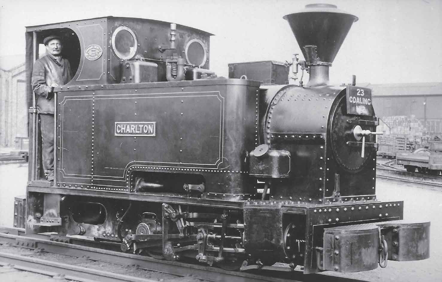
This view of Charlton appeared in The Locomotive in 1921 and it emphasizes the detail differences found on the 1916-built members of the class when compared with the two pioneering class members constructed a year earlier. The revised balance pipe and tank aperture arrangements referred to in the previous caption are very much in evidence in this picture, as are the modified sanding arrangements for the rear axle in which the sandboxes were mounted on the tanks. Collision damage to the right-hand side of the leading bufferbeam can also be seen in this view. (The Late Major Taylorson Collection via John Townsend)
A less detailed advertisement appeared in The Engineer of 20 April. The four locomotives were soon sold, but no details of any further wartime service on their part appear to have come to light. On 12 December 1919 an advertisement appeared in Machinery Market: ‘Four Locomotives 6 in. cyl. 8in. stroke brass tubes, copper firebox, steel boiler 160lbs pressure 18 inch gauge built 1911. Price £200 each. Kings, Garston Liverpool.’ This advertisement is of significant interest in that it reveals the extent to which some dealers were prepared to be economical with the truth during and immediately after the First World War. The boiler pressure is stated as 30psi greater than the safe working limit specified in the MED report, while the quoted building date of 1911 would appear to refer to the date (as previously suggested) of the locomotives’ rebuilding to ‘final standard form’. The specified boiler pressure was reduced to ‘about 140lb’ on 2 December 1921. The subsequent known history of these locomotives is recorded in Appendix IX, but none are believed to have survived the year 1922.
In November 1917 the Hornsby-Akroyd locomotive Atropos was authorized for disposal and was scrapped during the following year. Of the four remaining 6in x 8in Manning Wardles, all 1914 rebuilds, Fusee and Torpedo were authorized for disposal in February 1918 and, by 30 August of that year, both were in the hands of Darlington-based dealer John F. Wake, who promptly advertised them for re-sale in Machinery Market of that date. As detailed in Appendix IX, the former locomotive found its way to a Derbyshire colliery, but could hardly have been a success at its new home as it was re-advertised for sale between 1921 and 1924 before the loss of all further trace. During the month immediately prior to the Armistice, disposal of the three remaining Hornsby-Akroyd locomotives was authorized and lack of optimism on the part of the RAR authorities in relation to finding a buyer for them was reflected in the lack of progress made by the Ministry of Munitions in advertising for tenders at the time of compilation of the 1919 MED report. The policy of liquidating old and obsolete classes continued and disposal of the remaining two ‘1914 rebuild’ Manning Wardle 0-4-0STs Albert Edward and Gordon had been authorized by March 1919 with the locomotives following the other two 1914 rebuilds to J.F. Wake by August 1919. The former appears to have been re-sold as there is an entry in the Manning Wardle records (see Appendix VII) under Order No. 81231 for the supply of new firebars in 1920. Unfortunately no customer is specified and no firm evidence has come to light by the time of writing to indicate where, if at all, the locomotive subsequently operated. The possibility exists, as mentioned in Appendix IX, that Albert Edward accompanied Fusee to Derbyshire but this is far from a certainty according to the surviving evidence.
The next ‘class liquidation’ to be dealt with was that of the Bagnall 0-4-2 wing tanks, with Apis, Anubis and Osiris having been authorized for disposal by 31 March 1919. These locomotives apparently accompanied Gordon and Albert Edward to Darlington as they appeared in the same re-sale advertisement in Machinery Market on 10 August 1919. At this stage or shortly afterwards, the three Hornsby-Akroyd locomotives fell into Wake’s hands and consequently soon made their first appearance in the Darlington dealer’s advertisements. The 1918–19 MED report made reference to the fact that many months normally elapsed between the date when the Ministry of Munitions were asked to provide tenders for the disposal of a particular locomotive and the time when tenders were received. The consequence was that the locomotive in question deteriorated in the meantime and hence was less attractive to a prospective purchaser, while also out of use following withdrawal from service. This may have offered a plausible explanation to the MED staff as to why disposals may have attracted lower prices than might have been expected, but two further observations need to be made. The first is that many of the locomotives would have been in poor condition owing to the arduous rosters of the war years. The second observation, specific to the 18in-gauge fleet, is that while there may have been a small level of demand for second-hand locomotives of this gauge during the wartime period, this quickly evaporated following the Armistice. The subsequent story of the eight ex-RAR locomotives of this gauge left on Wake’s hands post-1920 illustrates this fact well, as will be seen later.
The process of rationalization of the Arsenal’s 18in-gauge locomotive fleet continued and Surplus of 1 May 1920 recorded among the locomotives being advertised for disposal by HM Government six John Fowler 0-4-0Ts [sic], Bagnall 0-4-0IST Ajax and the Baguley-McEwan-Pratt locomotive Megaera. The disposal of these locomotives appears to have been authorized at or around the time of the year-end review of March 1920, but the realities of the marketplace were now making their presence felt and no purchasers were immediately forthcoming. Although the descriptions of the locomotives in Surplus are not always accurate, it is possible to show that by 1 September 1920 the six Fowler 0-4-2Ts, Ajax and Megaera had been joined on the ‘prospective disposals’ list by three Hudswell Clarke 0-4-0STs, Achilles, Scipio and Hannibal. By this stage narrow-gauge locomotives earmarked for disposal appear to have been given numbers by the MED, with the Fowlers receiving the numbers MED 43–47 and 59, Ajax MED 51, while Achilles, Scipio and Hannibal were respectively designated MED 23, 25 and 26. By 15 November 1920 Basilisk had joined the 18in-gauge prospective disposals list, which now numbered some eleven steam locomotives plus the internal-combustion Megaera. Advertisements placed in The Engineer for 14 October 1921 and in Surplus the following day refer to an auction scheduled for 15 November 1921 that included inter alia fourteen 18in-gauge steam locomotives and one petrol locomotive of the same gauge. A feature in The Locomotive for October 1921 records that three of the Kerr, Stuart 0-4-0STs had been withdrawn from service by the time of its compilation (although not mentioned in the article, these were Pluto, Phaeton and Pegasus), hence it was this trio that brought the auction complement of steam locomotives to its advertised total. The November 1921 auction (which, according to The Engineer, was carried out under the auspices of Messrs Fuller, Horsey & Co.) was significant in that it was to be the last disposal from the Arsenal that resulted in an 18in-gauge locomotive being known to see further active service in a nonpreservation environment. The three Kerr, Stuart products and Megaera found purchasers and their subsequent history is recorded in Appendix IX.
The aftermath of the rationalization undertaken up to and including 15 November 1921 was that the RAR was left with 11 withdrawn 18in-gauge steam locomotives left over from the auction, plus 16 working Avonsides (which were not apparently scheduled for imminent withdrawal), 10 further Hudswell Clarke products and 7 further Kerr, Stuarts (two of which, Phoenix and Prometheus, had already been authorized for disposal according to Surplus). It is significant to record at this stage that the sum total of withdrawn locomotives (11 + 2 = 13) and working non-Avonsides (17 – 2 = 15) is equal to twenty-eight. The Engineer of 24 February 1922 carried an advertisement, again on behalf of Fuller Horsey, for an auction at the Arsenal on 23 March 1922 including twenty 18in-gauge locomotives. This shows that seven further such locomotives had been authorized for disposal since November 1921, but the market had clearly ‘fallen off the cliff’ by this stage and the auction appears to have been a total failure regarding all twenty. By 5 May 1922 a further six of the non-Avonside 18in-gauge locomotives had been authorized for disposal as The Engineer referred to another sale at the Arsenal that included twenty-six such locomotives. This was the point at which the patience of the Ministry of Munitions ran out and it was decided to accept any offer, even at scrap price levels. This sale was therefore exhaustive. As we have seen, this final acceptance of reality may also have been the last straw for further progress on the ‘Maunsell Mogul’ project whose curtailment was ordered shortly afterwards. As will be seen in Appendix IX, there appears to have been little enthusiasm on the part of the purchasers to attempt to re-sell most of the twenty-six locomotives as going concerns and most were probably scrapped almost immediately. The only exceptions were the five 1915 Hudswell Clarke products which were advertised, apparently unsuccessfully, by a Willenhall-based dealer in Machinery Market of 7 July 1922. Clearly this dealer was based far enough from London not to have heard of these locomotives’ poor reputation on the RAR.
The two remaining 18in-gauge ‘non-Avonsides’ were advertised for sale by the Arsenal in The Engineer of 25 August 1922 which referred to another Fuller Horsey auction of 19 September that year. Sadly, the advertisement did not specify the manufacturers, let alone the identities of these ‘bitter-enders’, but the most likely scenario is that they were from the last four built of the Kerr, Stuart 0-4-0STs. No further trace is recorded from this sale and it would thus appear that 1922 was very much the ‘year of Armageddon’ for a large portion of the RAR’s 18in-gauge locomotive fleet. After the end of 1924 there still remained the eight surviving 18in-gauge ex-RAR locomotives in the hands of J.F. Wake. Wake did not easily give up in his attempts to sell these over a period of about eight years and advertisements for them appeared in Surplus, The Engineer, Contract Journal, Colliery Guardian, Machinery Market and also his own catalogue. The descriptions of the locomotives in the periodicals were not always accurate (one advertisement in Contract Journal of 27 June 1923, for instance, refers to six 18in-gauge Manning Wardle 0-4-0STs and two oil-engined locomotives), but the decline in the market (and the locomotives’ deterioration while out of use) was reflected by a steady fall in the prospective sale price during this period. The final advertisement for them appeared in Machinery Market of 2 December 1927:
NARROW GAUGE LOCOMOTIVES
Five 18 in. gauge steam locomotives, overhauled, from £60 to £75 each.
Four 18 in. gauge locomotives with oil engines, by Hornsby, £70 to £85 each.
The quantity of Hornsby locomotives on offer was of course misstated, but be that as it may, other locomotives featured in this advertisement reappeared in another advertisement in the same journal for 13 January 1928 (notably some ex-Great Northern Railway specimens and the 2ft-gauge ex-North Wales Narrow Gauge Railway Hunslet ‘Single Fairlie’ 0-6-4T Gowrie of 1908). This was on behalf of the scrap dealers Hughes, Bolcow & Co. apparently operating from a base at Marske Aerodrome in North Yorkshire. There was no reference to the 18in-gauge locomotives which appear to have met their end at the hands of Hughes Bolcow’s men shortly before or after the turn of the year, in all probability without ever leaving Darlington.
Owing to the early interwar lull in activity, the Avonside locomotives’ survival as a fully intact class was destined to be relatively short. On a visit to the Arsenal by the late H.C. Casserley on the evening of 25 May 1932, Enfield, Charlton, Waltham and Sheffield were recorded (and photographed) in a locomotive shed that also contained Birmingham, Derby and Colchester. Glasgow, Leeds, Cardiff, Woolwich (wrongly identified in a letter to the author as a duplicated Sheffield) and Berkeley were recorded as being in the repair shop, while the only locomotive out at work was Manchester, which was photographed from both left and right. There was no reference to either Bristol or Liverpool and it may be that scrapping of these locomotives, or at least authorization for their disposal, had taken place between 4 September 1931 and 25 May 1932. Be that as it may, an advertisement appeared in Machinery Market of 13 January 1933 on behalf of the director of army contracts inviting tenders for surplus plant at the Arsenal that included 6 18in-gauge locomotives and 400 trucks. The same journal contained the following advertisement in its 10 March issue:
For sale six 18 inch gauge steam locomotives, cylinders 8½ in by 12 in., wheelbase 3 ft.3 in., working pressure 160 lb. per square inch, low price for immediate sale.
GEORGE COHEN & SONS LTD., 600 COMMERCIAL ROAD, LONDON E.14.

Fusee is illustrated in this photograph which appears to have been taken in 1919 by or on behalf of J.F. Wake as a means of advertising his work. The first point of significance to note is that the background, which would have emphasized the general air of untidiness that characterized Wake’s premises, has been obliterated. The photograph was clearly taken after the locomotive had been overhauled, as evidenced by the Wake rebuild plate fitted beneath the nameplate, and presumably after its sale had been agreed. The purchaser, the owner of Swanwick Collieries in Derbyshire, did not apparently request a repaint which (along with subsequent evidence) suggests that the purpose to which the locomotive was intended to be put was a relatively shortlived one. The similar styling of Fusee’s 1914 ‘final form’ rebuild to known illustrations of Albert Edward is apparent, but two important differences can also be seen: the spectacles are larger and the cab sides have a smooth ‘one-piece’ appearance with no waist beading. (Darlington Railway Museum)
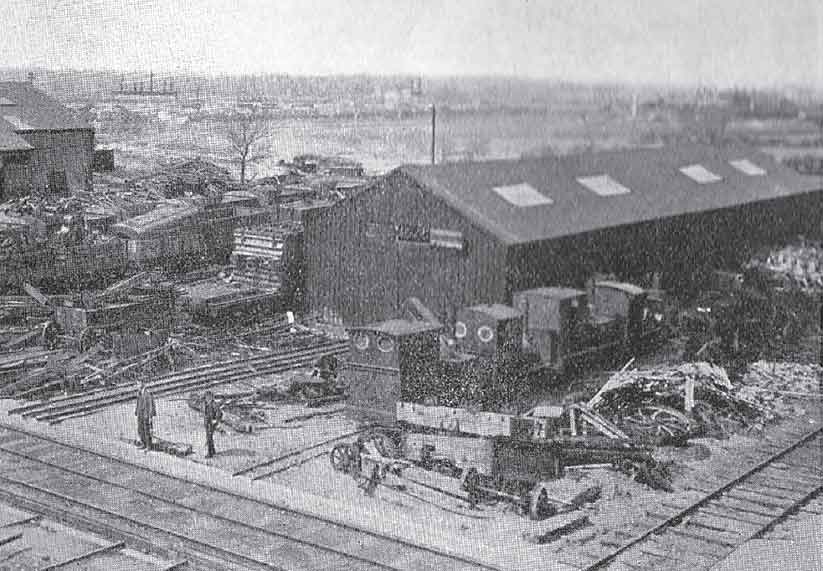
This illustration, albeit of relatively poor quality, is of vital historical importance as it shows the yard of John F. Wake, Geneva Works, Darlington, in 1922. Just below the centre of the picture can be seen one of the ex-RAR Bagnall ‘Suakin’ 0-4-2Ts, while following the 18in-gauge line upwards and to the right in the illustration reveals one of the Manning Wardle 0-4-0STs (either Gordon or Torpedo), another Bagnall 0-4-2T and one of the Hornsby 2-4-0 Akroyd locomotives. The existence of what appear to be further 18in-gauge lines leading into the building behind these locomotives suggests that the remaining locomotives of that gauge owned by Wake at the time were stored inside them. (Robin Waywell)
It is clear from the wording of the latter advertisement that Messrs Cohen & Sons had purchased six of the RAR’s Avonsides in January 1933, but what is not clear is why the Arsenal’s authorities decided to advertise this particular quantity of locomotives (and the associated 400 items of rolling stock) for external sale. Why, for instance, were all the locomotives not scrapped in-house or all advertised for external sale? Close examination of the 1931 Ordnance Survey Map suggests that the Arsenal’s capacity for the processing of scrap material may have declined somewhat after 1918, along with internal demand for such material. The wording of Cohen’s advertisement clearly indicates that the dealer was not optimistic about the prospects of selling such locomotives, with their rare gauge and 6-ton axle loading, as going concerns, especially after the rough handling they had received during the early part of their careers. There certainly appears to be no further evidence that any member of this batch of six locomotives ever turned a wheel again under its own steam after March 1933. This being the case, it would appear probable that at least five of the seven other Avonsides withdrawn at this time were sold direct to Messrs Cohen for scrap value without incurring the expense of inviting tenders for their disposal. This cannot be ascertained from surviving evidence, although it is known that Cohens supplied the Arsenal with reconditioned machine tools during the 1930s, hence a working commercial relationship existed between the two concerns during that decade. Given the delivery date of the locomotive to be discussed in the next paragraph, it would appear that the process of disposing of the thirteen unwanted Avonsides dragged on into 1934 but had certainly been completed, according to O.F.G. Hogg, in The Royal Arsenal Volume II (Oxford University Press, 1963), by 1936.
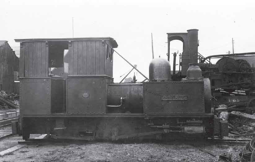
Bagnall 0-4-2T Osiris is illustrated in this view in Wake’s Yard, probably towards the end of its sojourn there, although not right at the end as a tree in full leaf can be discerned in the background immediately above the furthest forward of the two visible boiler bands. The view appears to be a specially-posed one (possibly for Ted Haigh or Ken Hoole: the tree would be consistent with the former as he visited the premises on 7 June 1925) and, given the fact that the locomotive was not in working order (a rust hole can be discerned in the smokebox immediately below the leading portion of the chimney), this implies that Wake must have had some mechanical means of moving it, say a winch or tractor. Close examination of Osiris reveals the cumulative modifications made at the Arsenal over the years, i.e. the wooden cab infill, stays linking the cab and wing tanks, RAR-pattern buffers, reduced-diameter trailing wheels (to allow for a greater swing of the rear Bissell truck and mitigate the limitations imposed by the locomotive’s 8ft wheelbase), and ‘Neath’-pattern spark arrester (on this occasion accompanied by a rather ugly tapered chimney). The year of the locomotive’s acquisition by Wake, 1919, can also be seen, painted on the boiler cladding immediately to the left of the right-hand leading sandbox). Immediately behind the leading portion of Osiris can be seen much of the pioneering Hornsby locomotive Lachesis. The cab modifications made within the Arsenal are much in evidence, as is the fact that the true shape of the handbrake column can now be seen as the original fairing was disposed of prior to the date of the photograph. Of greater significance is the replacement exhaust pipe leading to a replacement cooling tower (not shown) which was proof of the locomotive’s conversion during its operating career to the 2-4-0 wheel arrangement, a fact recorded in an advertisement in Machinery Market of 7 January 1927. (Darlington Railway Museum)

‘Your candle burned out long before your legend ever did.’ One of the last two surviving home-based 18in-gauge ‘6in’ Manning Wardles, Gordon was photographed on the same day on the same stretch of track as the previous photograph was taken. Much altered and obsolete in an era long before its design’s historical significance was appreciated by the bulk of enthusiasts at large, the engine certainly presented a very sad picture when compared with the publicity that greeted the newly-built Lord Raglan in 1871–3. Just to illustrate the level of decline in the market for second-hand locomotives of this general type during the decade following the Armistice, Gordon’s sisters Torpedo and Fusee were advertised for sale at £450 each by Wake in November 1918. By 7 January 1927, Gordon and Torpedo, along with the three Bagnall 0-4-2Ts, were priced at £125, the two 9.5hp Hornsby 2-4-0s at £175 each and the opposed-piston 15hp Hornsby 2-4-0 Alecto at £200. All were described as ‘thoroughly overhauled’, although it appears certain that no such work was ever done on them. As recorded in the text, these 18in-gauge ex-RAR survivors failed to attract interest as going concerns even at these reduced prices and fell to the breaker’s torch about a year after the January 1927 advertisement. (Darlington Railway Museum)
Four coal-fired 18in-gauge Avonsides, Enfield, Charlton, Waltham and Sheffield, are seen in the locomotive shed on 25 May 1932. Despite being relatively new at the time of the Armistice, the combination of the reduced activity between 1919 and 1936, and the increasing reliance on the standard-gauge network for much of the remaining traffic ensured that the life of all these locomotives beyond the date of photography could probably only be counted in months. Nonetheless, all four locomotives were awaiting preparation for duty and the kindling wood for their fireboxes can be seen alongside their cab entrances. (The late H.C. Casserley)
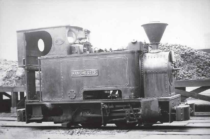
108. This right-hand view of Manchester close to the East Wharf on 25 May 1932 shows the modifications made to the locomotive during the first sixteen years of its career on the RAR. The roof was extended at the rear and a rear spectacle plate fitted, while both pairs of sandboxes were relocated from their original position (as was also the case with Enfield and Charlton) with the leading pair being mounted above the tanks rather than remaining in front of them as was the case with Waltham, Sheffield and Woolwich. (The late H.C. Casserley)
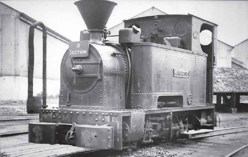
By 1936 only three 18in-gauge steam locomotives – Manchester, Woolwich and Newcastle – remained in service on the RAR system. The first mentioned of these is seen on 25 May 1932 coaling in preparation for duty, as its Duty Board proclaims, on ‘D’ Section. The location would appear to be the coal bunker, adjacent to the East Wharf and many of the ‘D’ buildings. The practice of carrying Duty Boards had become established by 1916, although at that stage at least there was no requirement for it to be universal (Duty Boards were also carried by 18in-gauge locomotives used by the Royal Army Service Corps at Deptford during the First World War) and they do not appear on most 1950s photographs. Manchester was destined to be the last coal-fired 18in-gauge steam locomotive in service on the RAR, ultimately falling to the breaker’s torch in the 1950s. (The late H.C. Casserley)
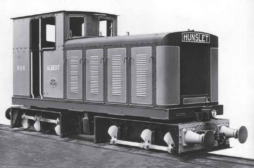
The disposal of most of the Avonside locomotives during the early 1930s resulted in the need for a suitable, more modern, source of motive power for use on the rationalized 18in-gauge part of the RAR system. By this stage the true diesel locomotive was making its commercial presence felt, and the Arsenal turned to Hunslet Engine Co of Leeds to construct the first such locomotive built specifically for use at the Woolwich site. The makers came up with this rod-coupled double-bogie 75hp design, which entered service in 1934 and was named Albert. (Maker’s photograph courtesy Don Townsley)
In 1934 the RAR took delivery of its first true diesel locomotive and in doing so turned to a supplier not hitherto resorted to for new locomotives. The preceding decade or so had seen British manufacturers embrace diesel traction on a commercial scale and much of this work had been undertaken in connection with narrow-gauge units. In 1930 Avonside Engine Co. produced a rod-coupled 2ft-gauge double-bogie diesel locomotive for Ellingham Estates in South Africa and this lead was followed by Hunslet Engine Co. when it supplied Albert (Works No. 1722) for use on the 18in-gauge RAR network. Fitted with a McLaren-Benz 75hp diesel engine (started with the aid of a Scott 16/17hp two-stroke petrol engine) driving through a pre-selector two-speed gearbox via Cardan shafts and bevel gearing to jackshafts on the bogies, this locomotive must have seemed a major advance on the previous units used by the RAR locomotive crews. The locomotive, which was just over 18ft long over bufferbeams and weighed 13.25 tons in working order, was capable of negotiating curves of 30ft radius and could work on rails as light as 20lb/yd. The obvious choice for the ‘long haul’ 18in-gauge workings to the eastern part of the Arsenal, Albert relegated the three remaining Avonsides to shop work and ‘spare engine’ capacity when it was under repair. As if to emphasize the comparative long-haul nature of the locomotive’s work, the flexible composite buffers, a major feature of RAR narrow-gauge locomotives employed in shop work, were discarded on Albert in favour of buffers of conventional pattern.

This is the maker’s Pipe Arrangement Drawing of Albert. The McLaren-Benz MDB4 four-cylinder engine can be seen in both elevation and plan views, immediately above the leading bogie, with the main clutch (Hunslet patent plate design) located immediately to the rear. The intermediate transmission consisted of a Hardy-Spicer shaft (located to the rear of the main clutch) with the main gearbox being located below between the bogies. From this gearbox, the drive was taken via universal shafts to worm gearboxes (situated at the outward ends of the bogies) equipped with transverse output jackshafts driving the bogie axles via coupling rods. The main gearbox was fitted with Hunslet pre-selector gearing arranged to two speeds (4 and 8 miles per hour) in either direction when the engine was running at its intended speed of 1,000rpm. Starting was accomplished by means of a 16 to 19hp Scott petrol engine located on the right-hand side of the locomotive. This is visible in the plan view adjacent to the main clutch. Dual hand and air-braking was employed, and the air compressor was situated on the leading left-hand side of the locomotive, level with the front of the main engine and immediately behind the radiator. The whistle was also actuated by means of this power source. As Albert was intended for relatively long-distance working between the shops and the eastern magazines rather than working on the minimum radius curves inside and immediately outside the shops themselves, the flexible composite buffer arrangement, hitherto standard on the 18in gauge, was dispensed with in favour of buffers of a more conventional pattern.
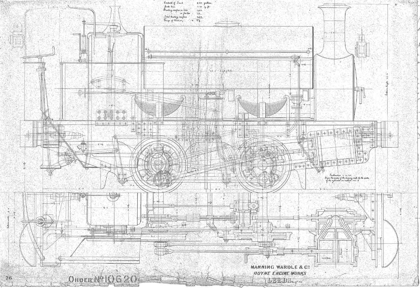
This is the maker’s drawing of Gunner which illustrates the constructional features of the engine in detail. Rather sadly, and as is the case with other surviving Manning Wardle drawings, no front elevation was included. (Maker’s drawing)
The next incursion of diesel motive power into the RAR narrow-gauge fleet came in the form of a product of Ruston Hornsby & Co., the successor company to the manufacturer of the RAR’s earliest internal combustion unit more than four decades earlier. Completed by December 1938 and delivered during the following month, Works No. 192886 was in most essential respects one of the maker’s standard 11/13hp four-wheel units, being equipped with the class standard Ruston 2VTO engine. However, certain special features were incorporated according to customer requirements. These included radiator as opposed to simple water-tank cooling, a two-speed gearbox, an exhaust filter and deepened side mainframes. One of the most obvious alterations to the casual observer was axle bearings relocated outwards in order to accept drive sprockets also moved outwards to accommodate final drive chains repositioned to cater for the reduction in gauge from the customary nominal 2ft. The other obvious deviation from the norm was the reappearance of RAR-pattern composite buffers, albeit of the non-flexible variety. The locomotive was clearly intended for light shop work, a task for which it appears to have been admirably suited.
Leslie S. Robertson’s paper Narrow Gauge Railways – Two Feet and Under stated that in 1898 there were nine standard-gauge locomotives in use on the Arsenal’s railway system, from which it is possible to show that Manning Wardle’s monopoly on the supply of new standard-gauge locomotives (apart from the previously-mentioned compressed air experiments) was not broken until 1888, by which time five of the company’s products were in service on the standard-gauge network. In 1888, however, Hawthorn Leslie was chosen as the supplier for a new 0-4-0ST Bombard (Maker’s No. 2115) with 15in bore and 21in stroke cylinders that was clearly intended for similar duties to Gunner. As with Gunner, Bombard possessed composite buffers and the engine was readily distinguishable from its pre-1902 contemporaries by its fully-rounded saddle tank section. Two more new non-Manning Wardle products followed during the ensuing decade, namely Vulcan Foundry 0-4-0ST Vulcan (Maker’s No. 1399 of 1893) and Hudswell Clarke 0-4-0ST Cyclops (451 of 1895). These were somewhat smaller than Bombard and both will appear in subsequent illustrations. (Maker’s photograph)
As mentioned in Chapter Five, two 2ft-gauge Hibberd four-wheel 12/16hp diesels were purchased by the Arsenal in February and March 1940 (Works Nos 2232 and 2233) for use on the River Wall repair system. These 2.5-ton locomotives were fitted with Ailsa Craig CD2 engines. Their operational career at Woolwich was a short one and they were not noted as operational or even on site during any visits by interested parties at the end of the 1940s. They would appear to have been disposed of at this stage, but the purchaser is unknown.
The steam locomotive was to attempt a late swan song on the 18in-gauge portion of the RAR. With the Second World War now well under way, an oil-fired 0-4-0ST was ordered from Bagnall in May 1940 to boost the ‘shop’ capability. The proposed locomotive was to have been equipped with 7in x 12in cylinders, Walschaerts valve gear and a Bullhead-pattern boiler with cylindrical firebox, all features found today on home-based 2ft-gauge survivors Peter, Woto and Sir Tom. Unlike these locomotives, however, the RAR example would have been equipped with a saddle tank extending over the smokebox and outside mainframes and flycranks. The engine was allocated Maker’s No. 2636 but the ready availability of suitable small diesel locomotives for its intended duties spelled the death-knell for the project and the order was cancelled in December 1940. The final additions to the RAR narrow-gauge locomotive fleet during the Second World War were two Ruston Hornsby 20 DL (20hp) four-wheel diesel locomotives originally constructed in 1942 as Works Nos 213839 and 213840 of that year. These locomotives were originally delivered to Lion Brickworks, Scalford, Leicestershire, (see Appendix IX) as 19in-gauge units and hence required relatively little gauge alteration, having been fitted when delivered with axle bearing and final drive arrangements similar to Works No. 192886. As with this latter locomotive, they were acquired with shop work in mind, but they appear never to have been equipped with RAR-pattern composite buffers. In general styling they followed their nominal 2ft-gauge Ministry of Supply sister locomotives of the period, incorporating the ‘slopesided’ bonnet in preference to the earlier bonnet design of the 16/20hp locomotives from which they were developed. They did, however, retain the 2VSO engine utilized by their precursors.
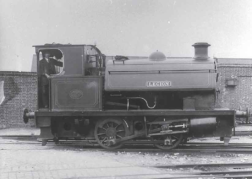
Coal-fired Hawthorn Leslie 14in x 22in 0-4-0ST Legion (3187 of 1916) is shown to advantage in this right-hand view. This photograph was part of a collection intended for use in The Locomotive, but in the event not published with the 1921 feature. Some fourteen locomotives of this type were supplied by the Newcastle-upon-Tyne manufacturer to the Arsenal between 1915 and 1916, with the class being equally divided between coal- and oil-fired members. Two other Hawthorn Leslie 0-4-0STs were also constructed for the RAR during the First World War, namely Cynthia and Cleopatra. These were both coal-fired, were smaller than the others and possessed cylinders 12in x 18in. (The Late Major Taylorson Collection via John Townsend)
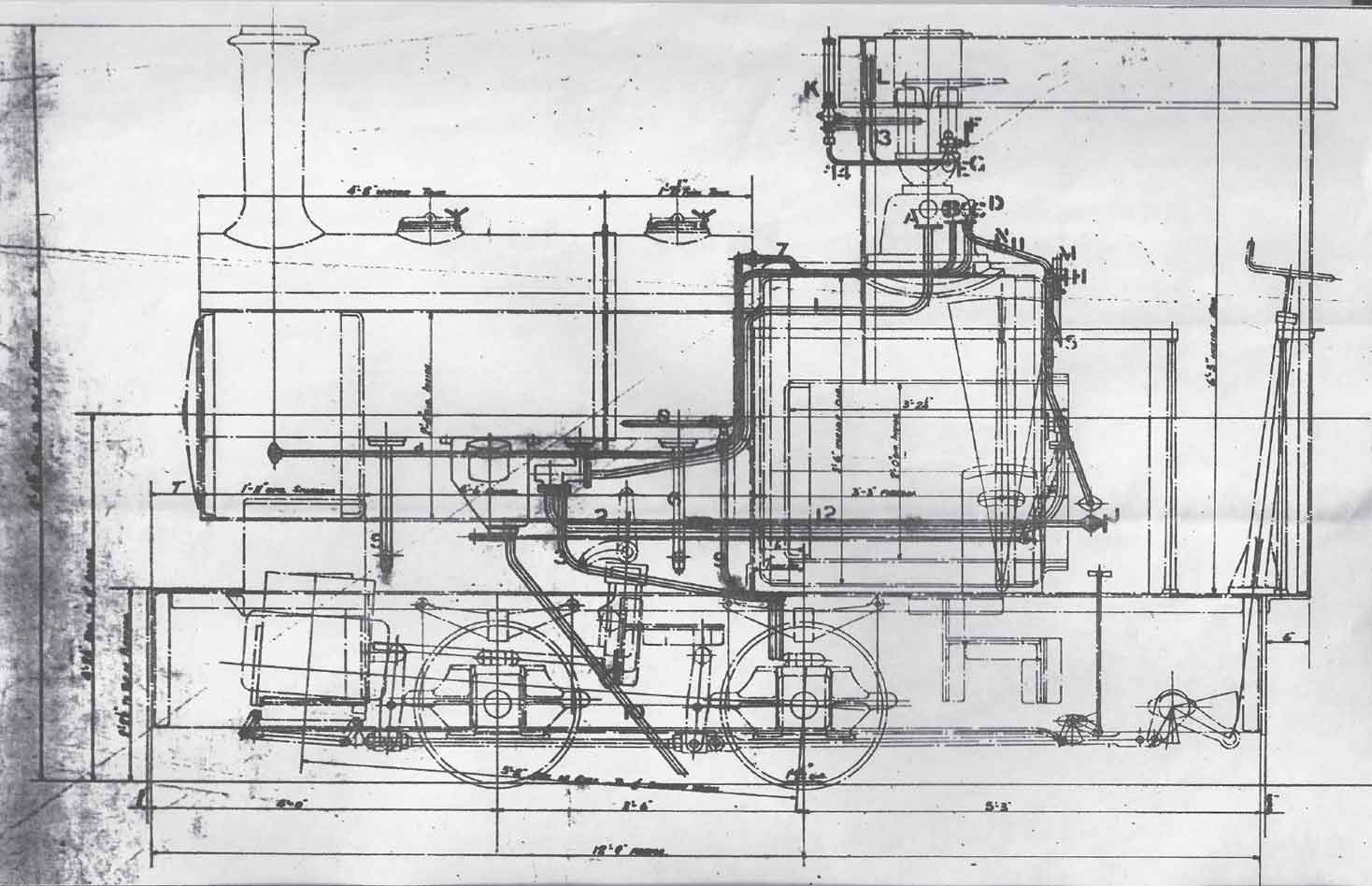
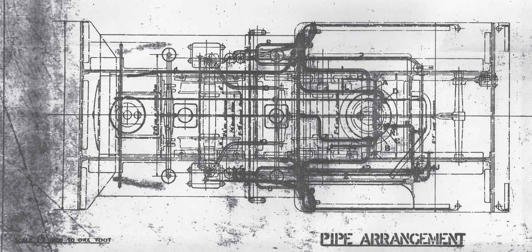
The final steam locomotive design proposed for use on the RAR’s 18in-gauge system is illustrated by this Bagnall Pipe Arrangement Drawing. Allocated Maker’s No. 2636, this locomotive, if completed, would have been the last functional (i.e. non-miniature or tourist-orientated) 18 inch gauge steam locomotive produced by a British manufacturer. Much of the locomotive appears to have been completed prior to cancellation of the order and these components (including the tank extending over the smokebox) were incorporated into an inside-framed 2ft-gauge locomotive completed for UNNRA after the cessation of hostilities. (Maker’s drawing courtesy the late Allen Civil)
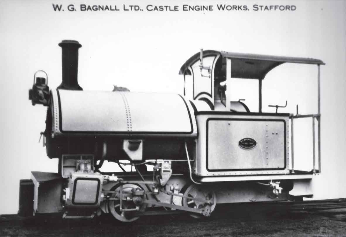
This photograph shows Bagnall 2636 as eventually completed for UNNRA. (Maker’s photograph courtesy the late Allen Civil)
According to notes compiled by a Mr P.E.W. Scott, who worked in the Arsenal during most of the Second World War, the three surviving Avonsides, Newcastle, Woolwich and Manchester, were at this stage painted in green, lined out in black, fine-lined white with red bufferbeams, the general appearance being rather faded and ‘knocked about’. Albert was brown with red bufferbeams and rods and remaining items below running-board level being black.
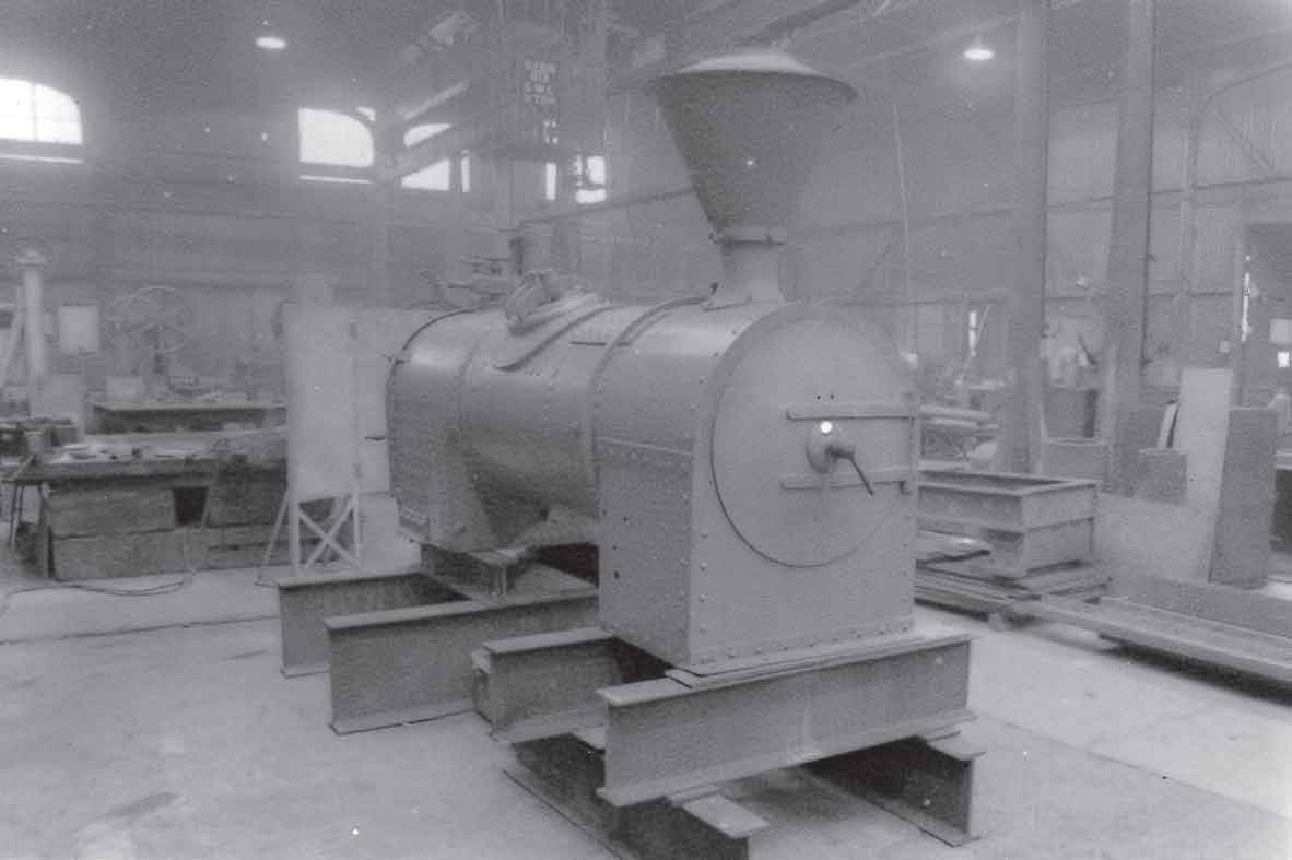
Although the Royal Arsenal Railways system was well into its declining years by the early 1950s, some improvements and alterations were still being made to the locomotives and rolling stock in order to keep the railway running. One of these was an extensive overhaul for the oil-fired 18in-gauge Avonside locomotive Woolwich in 1952–4. Part of the work entailed extensive reconstruction of the locomotive’s boiler. The boiler is seen here with the work at an advanced stage in Building D59 on 23 December 1952. (Greenwich Heritage Centre)

Although the 18in gauge had a very much reduced role by the 1950s when compared with the busy years of the First World War, some track in the eastern magazines remained exclusively 18in gauge until the end of the railway’s operation. The loss of the steam locomotives Newcastle and Manchester between 1949 and 1956 created a shortage of 18in-gauge motive power suitable for hauling long ammunition trains from their production sites (located in mixed-gauge territory) to the magazines. This gap was filled in 1954 by the purchase of a new diesel locomotive Carnegie from Hunslet Engine Co. Ltd as Maker’s No. 4524. Carnegie was an updated version of Albert (Hunslet 1722) produced twenty years earlier. This is the maker’s Pipe Arrangement Drawing of Carnegie showing the improvements that were made from Albert’s design. Apart from increased engine power (88hp as opposed to 75hp), electric starting and cab heating were employed. Nonetheless, the success of the basic design in ensuring a meaningful role for locomotive-hauled 18in-gauge operation on the RAR during the mid-twentieth century cannot be disputed. Despite its gauge, Carnegie was more powerful than many standard-gauge diesel locomotives. (Maker’s drawings)
A visit to the Arsenal by Eric Hannan on Monday, 29 August 1949 revealed evidence of all three of the Avonsides being still on site, although Newcastle was sighted only as ‘frame derelict in shed, no boiler or cab, two tanks with name attached noted’. No reference was made to the three Ruston diesels, although it appears that they were not considered of sufficient significance to note. Russell Wear noted on 21 June 1951 that the frames of Woolwich were in the shed with other components being in the workshops; Manchester, despite being a coal-fired locomotive, was stated to be out in the Danger Area and, according to a young shed foreman, Newcastle had been sold to a slate quarry in Wales. No supporting evidence has been found for this latter assertion, which was extremely unlikely given the nature and operating practices of the narrow-gauge railway systems associated with Welsh slate quarries. The only inference that can be drawn from the known facts regarding this locomotive is that which appears in Appendix IX. The overhaul of Woolwich appears to have been a protracted affair as photographs taken during the following year show the locomotive’s boiler undergoing a very extensive rebuild. Nonetheless, being an oil-fired locomotive, its usefulness for Danger Buildings shop work was the crucial factor that prolonged its operational career into the second half of the 1950s. Manchester appears to have spent much of its final years as a spare long-haul engine to Albert and, once the latter locomotive was supplemented in 1954, would have had little if any further useful function. The information supplied for inclusion in the Universal Directory of Railway Officials and Year Book suggests that Manchester was taken out of service around March 1954. Albert’s new stablemate was Carnegie (Hunslet Engine Co. Works No. 4524 of 1954), a locomotive of similar design but with engine performance upgraded to 88hp and other refinements such as electrically-powered starting and cab heating. The post-Suez rundown of railway traffic ensured that there was no further use for Woolwich, hence the operational steam era on the 18in gauge ended. The remaining shop work proved insufficient for even the three Ruston Hornsby locomotives and Works No. 213839 was also withdrawn from service around this time. Both these locomotives were sold to the dealer E.L. Pitt of Brackley during the late 1950s, as recorded in Appendix IX. By 1961 the long-haul magazine traffic had dwindled to the extent that only one double-bogie diesel locomotive was required and Albert was withdrawn from service. Sadly, this historically-important locomotive was destined to slip through the preservation net, passing to a Warrington scrap dealer after disposal. Carnegie soldiered on until 1964, passing to an Essex dealer by the end of that year and eventually, following the Brackley sales, to pastures new. The division of what remained of the Arsenal in 1971 saw the departure of the two remaining Ruston Hornsby locomotives following an auction held at Chatham on 6 April of that year. Works No. 213840 was designated Lot No. 262 and, following sale, was converted to 2ft gauge for further use. Works No. 192886 (Lot No. 263) was sadly destined to meet no other end but the breaker’s torch. The era of 18in-gauge locomotives on the Arsenal’s railway system had lasted a century and the narrow-gauge world was certainly a less interesting and diverse place for its passing.

