Chapter 4
Physical Layer
Objectives
Upon completion of this chapter, you will be able to answer the following questions:
What are the purpose and functions of the physical layer in a network?
What are the characteristics of the physical layer?
What are the basic characteristics of copper cabling?
How is UTP cable used in Ethernet networks?
What is fiber-optic cable, and what are its main advantages over other media?
How do you connect devices using wired and wireless media?
Key Terms
This chapter uses the following key terms. You can find the definitions in the glossary at the end of the book.
wireless access point (AP) page 138
network interface card (NIC) page 139
International Organization for Standardization (ISO) page 141
Telecommunications Industry Association/Electronic Industries Association (TIA/EIA) page 141
International Telecommunication Union (ITU) page 141
American National Standards Institute (ANSI) page 141
Institute of Electrical and Electronics Engineers (IEEE) page 141
electromagnetic interference (EMI) page 147
unshielded twisted-pair (UTP) page 148
Introduction (4.0)
The physical layer of the OSI model sits at the bottom of the stack. It is part of the network access layer of the TCP/IP model. Without the physical layer, you would not have a network. This chapter explains, in detail, the three ways to connect to the physical layer. Packet Tracer activities and a lab will give you the confidence you need to cable up your own network! Let’s get busy!
Purpose of the Physical Layer (4.1)
All data being transferred over a network must be represented on a medium by the sending node and interpreted on a medium by the receiving node. The physical layer is responsible for these functions. This section explores the physical layer.
The Physical Connection (4.1.1)
Whether connecting to a local printer in a home or to a website in another country, before any network communications can occur, a physical connection to a local network must be established. A physical connection can be a wired connection using a cable or a wireless connection using radio waves.
The type of physical connection used depends on the setup of the network. For example, in many corporate offices, employees have desktop or laptop computers that are physically connected, via cable, to a shared switch. This type of setup is a wired network. Data is transmitted through a physical cable.
In addition to wired connections, many businesses also offer wireless connections for laptops, tablets, and smartphones. With wireless devices, data is transmitted using radio waves. Wireless connectivity is common as individuals and businesses alike know its advantages. Devices on a wireless network must be connected to a wireless access point (AP) or wireless router like the one shown in Figure 4-1.
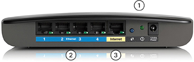
Figure 4-1 Wireless Router
The numbers in Figure 4-1 indicate the components of an access point:
The wireless antennas (which are embedded inside the router version shown in Figure 4-1)
Several Ethernet switchports
An internet port
Much like corporate offices, most homes offer both wired and wireless network connectivity. Figure 4-2 shows a home router and a laptop connecting to the local-area network (LAN).
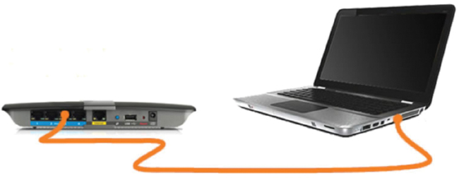
Figure 4-2 Wired Connection to a Wireless Router
A network interface card (NIC) connects a device to a network. Ethernet NICs are used for wired connections, as shown in Figure 4-3, whereas wireless local-area network (WLAN) NICs are used for wireless. An end-user device may include one or both types of NIC. A network printer, for example, may only have an Ethernet NIC, in which case it must connect to the network using an Ethernet cable. Other devices, such as tablets and smartphones, might only contain a WLAN NIC and must use a wireless connection.

Figure 4-3 Wired Connection Using an Ethernet NIC
Not all physical connections are equal, in terms of the performance level, when connecting to a network.
The Physical Layer (4.1.2)
The OSI physical layer provides the means to transport the bits that make up a data link layer frame across the network media. This layer accepts a complete frame from the data link layer and encodes it as a series of signals that are transmitted to the local media. The encoded bits that comprise a frame are received by either an end device or an intermediate device.
Figure 4-4 show an example of the encapsulation process. In the last part of this process, the bits are sent over the physical medium. The physical layer encodes the frames and creates the electrical, optical, or radio wave signals that represent the bits in each frame. These signals are then sent over the media, one at a time.
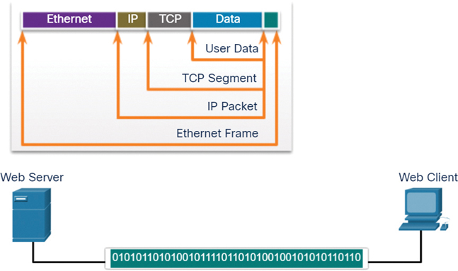
Figure 4-4 Bits Transported over the Medium
The destination node physical layer retrieves these individual signals from the media, restores them to their bit representations, and passes the bits up to the data link layer as a complete frame.

Refer to the online course to view an animation of the encapsulation process.
Check Your Understanding—Purpose of the Physical Layer (4.1.3)
Refer to the online course to complete this activity.
Physical Layer Characteristics (4.2)
At the foundation of network communications is the physical layer, Layer 1. This section examines standards and components that make up the physical layer.
Physical Layer Standards (4.2.1)
The previous section provides a high-level overview of the physical layer and its place in a network. This section dives a bit deeper into the specifics of the physical layer. It looks at the components and the media used to build a network, as well as the standards that are required so that everything works together.
The protocols and operations of the upper OSI layers are performed using software designed by software engineers and computer scientists. The services and protocols in the TCP/IP suite are defined by the Internet Engineering Task Force (IETF).
The physical layer consists of electronic circuitry, media, and connectors developed by engineers. Therefore, it is appropriate that the standards governing this hardware are defined by the relevant electrical and communications engineering organizations.
Many different international and national organizations, regulatory government organizations, and private companies are involved in establishing and maintaining physical layer standards. For instance, the physical layer hardware, media, encoding, and signaling standards are defined and governed by the following standards organizations (see Figure 4-5):
Telecommunications Industry Association/Electronic Industries Association (TIA/EIA)
National telecommunications regulatory authorities, including the Federal Communications Commission (FCC) in the United States and the European Telecommunications Standards Institute (ETSI)
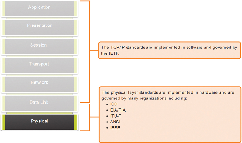
Figure 4-5 Physical Layer Standards Organizations
In addition to these, there are many regional cabling standards groups that develop local specifications, such as CSA (Canadian Standards Association), CENELEC (European Committee for Electrotechnical Standardization), and JSA/JIS (Japanese Standards Association).
Physical Components (4.2.2)
The physical layer standards address three functional areas:
Physical components
Encoding
Signaling
The physical components are the electronic hardware devices, media, and other connectors that transmit the signals representing bits. Hardware components such as NICs, interfaces and connectors, and cables (including cable materials and cable designs) are all specified in standards associated with the physical layer. The various ports and interfaces on a Cisco 1941 router are also examples of physical components with specific connectors and pinouts based on standards.
Encoding (4.2.3)
Encoding, or line encoding, is a method of converting a stream of data bits into a predefined “code.” Codes are groupings of bits used to provide a predictable pattern that can be recognized by both a sender and a receiver. In other words, encoding is a method or pattern used to represent digital information. This is similar to how Morse code encodes a message using a series of dots and dashes.
For example, Manchester encoding represents a high- to low-voltage transition as a 0 bit and a low- to high-voltage transition as a 1 bit. An example of Manchester encoding is illustrated in Figure 4-6. The transition occurs at the middle of each bit period. This type of encoding is used in 10 Mbps Ethernet. Faster data rates require more complex encoding. Manchester encoding is used in older Ethernet standards, such as 10BASE-T. Ethernet 100BASE-TX uses 4B/5B encoding, and 1000BASE-T uses 8B/10B encoding.
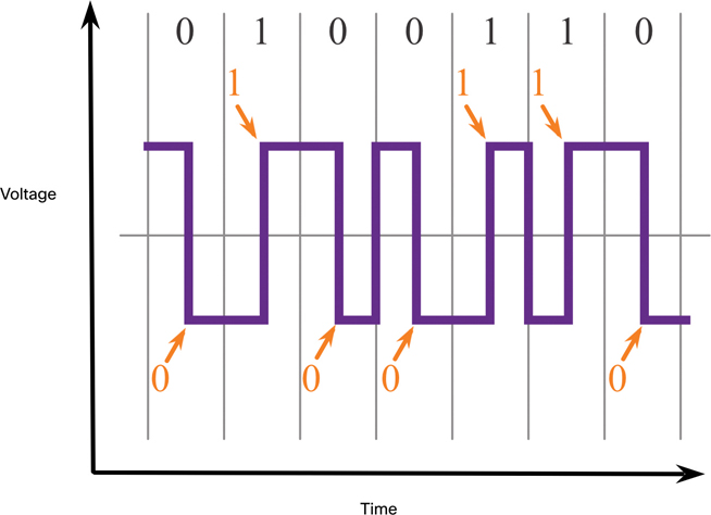
Figure 4-6 Manchester Encoding
Signaling (4.2.4)
The physical layer must generate the electrical, optical, or wireless signals that represent the 1s and 0s on the media. The way that bits are represented is called the signaling method. The physical layer standards must define what type of signal represents a 1 and what type of signal represents a 0. This can be as simple as a change in the level of an electrical signal or optical pulse. For example, a long pulse might represent a 1, whereas a short pulse might represent a 0. This is similar to the signaling method used in Morse code, which may use a series of on/off tones, lights, or clicks to send text over telephone wires or between ships at sea.
Figures 4-7 through 4-9 show illustrations of signaling for copper cable, fiber-optic cable, and wireless media.
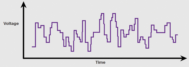
Figure 4-7 Electrical Signals over Copper Cable
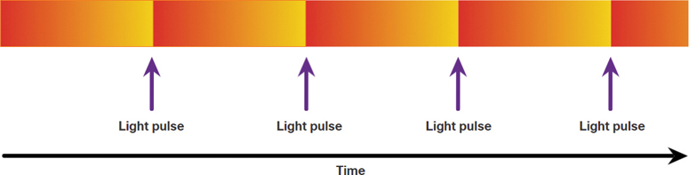
Figure 4-8 Light Pulses over Fiber-Optic Cable
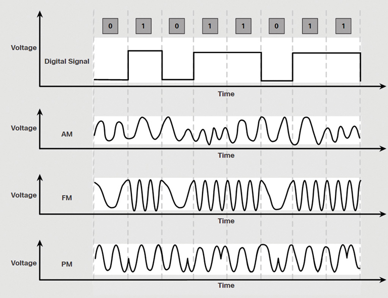
Figure 4-9 Microwave Signals over Wireless
Bandwidth (4.2.5)
Different physical media support the transfer of bits at different rates. Data transfer is usually discussed in terms of bandwidth. Bandwidth is the capacity at which a medium can carry data. Digital bandwidth measures the amount of data that can flow from one place to another in a given amount of time. Bandwidth is typically measured in kilobits per second (Kbps), megabits per second (Mbps), or gigabits per second (Gbps). Bandwidth is sometimes thought of as the speed that bits travel, but this is not accurate. For example, in both 10 Mbps and 100 Mbps Ethernet, the bits are sent at the speed of electricity. The difference between 10 Mbps and 100 Mbps Ethernet is the number of bits transmitted per second.
A combination of factors determines the practical bandwidth of a network:
The properties of the physical media
The technologies chosen for signaling and detecting network signals
Physical media properties, current technologies, and the laws of physics all play roles in determining the available bandwidth.
Table 4-1 shows the commonly used units of measure for bandwidth.
Table 4-1 Bandwidth Units
Unit of Bandwidth |
Abbreviation |
Equivalence |
Bits per second |
bps |
1 bps = fundamental unit of bandwidth |
Kilobits per second |
Kbps |
1 Kbps = 1000 bps = 103 bps |
Megabits per second |
Mbps |
1 Mbps = 1,000,000 bps = 106 bps |
Gigabits per second |
Gbps |
1 Gbps = 1,000,000,000 bps = 109 bps |
Terabits per second |
Tbps |
1 Tbps = 1,000,000,000,000 bps = 1012 bps |
Bandwidth Terminology (4.2.6)
Terms used to measure the quality of bandwidth include
Latency
Throughput
Goodput
Latency
Latency refers to the amount of time, including delays, for data to travel from one point to another.
In an internetwork, or a network with multiple segments, throughput cannot be faster than the slowest link in the path from source to destination. Even if all, or most, of the segments have high bandwidth, it takes only one segment in the path with low throughput to create a bottleneck in the throughput of the entire network.
Throughput
Throughput is the measure of the transfer of bits across the media over a given period of time.
Due to a number of factors, throughput usually does not match the specified bandwidth in physical layer implementations. Throughput is usually lower than the bandwidth. Many factors that influence throughput, including the following:
The amount of traffic
The type of traffic
The latency created by the number of network devices encountered between source and destination
There are many online speed tests that can reveal the throughput of an internet connection.
Goodput
There is a third measurement to assess the transfer of usable data: goodput. Goodput is the measure of usable data transferred over a given period of time. Goodput is throughput minus traffic overhead for establishing sessions, acknowledgments, encapsulation, and retransmitted bits. Goodput is always lower than throughput, which is generally lower than the bandwidth.
Check Your Understanding—Physical Layer Characteristics (4.2.7)
Refer to the online course to complete this activity.
Copper Cabling (4.3)
One of the oldest and most used media for communications is copper cabling. This section examines the characteristics and use of copper media in data networks.
Characteristics of Copper Cabling (4.3.1)
Copper cabling is the most common type of cabling used in networks today. In fact, copper cabling is not just one type of cable. There are three different types of copper cabling that are each used in specific situations.
Networks use copper cabling because it is inexpensive and easy to install, and it has low resistance to electrical current. However, copper cabling is limited by distance and signal interference.
Data is transmitted on copper cables as electrical pulses. A detector in the network interface of a destination device must receive a signal that can be successfully decoded to match the signal sent. However, the farther the signal travels, the more it deteriorates. This is referred to as signal attenuation. For this reason, all copper media must follow strict distance limitations, as specified by the guiding standards.
The timing and voltage values of electrical pulses are also susceptible to interference from two sources:
Electromagnetic interference (EMI) or radio frequency interference (RFI): EMI and RFI signals can distort and corrupt the data signals being carried by copper media. Potential sources of EMI and RFI include radio waves and electromagnetic devices, such as fluorescent lights or electric motors.
Crosstalk: Crosstalk is a disturbance caused by the electric or magnetic fields of a signal on one wire to the signal in an adjacent wire. In telephone circuits, crosstalk can result in hearing part of another voice conversation from an adjacent circuit. Specifically, when an electrical current flows through a wire, it creates a small, circular magnetic field around the wire, which can be picked up by an adjacent wire.
Figure 4-10 shows how data transmission can be affected by interference:
A pure digital signal is transmitted.
On the medium, there is an interference signal.
The digital signal is corrupted by the interference signal.
The receiving computer reads a changed signal. Notice that a 0 bit is now interpreted as a 1 bit.
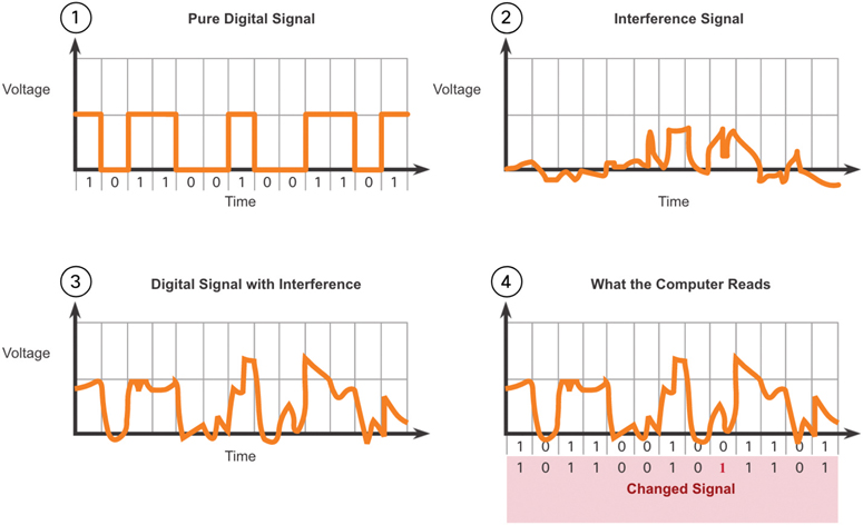
Figure 4-10 Effect of Interference on Data Transmission
To counter the negative effects of EMI and RFI, some types of copper cables are wrapped in metallic shielding and require proper grounding connections.
To counter the negative effects of crosstalk, some types of copper cables have opposing circuit wire pairs twisted together, which effectively cancels the crosstalk.
The susceptibility of copper cables to electronic noise can also be limited by
Selecting the cable type or category most suited to a given networking environment
Designing a cable infrastructure to avoid known and potential sources of interference in the building structure
Using cabling techniques that include the proper handling and termination of the cables
Types of Copper Cabling (4.3.2)
There are three main types of copper media used in networking, as shown in Figure 4-11.
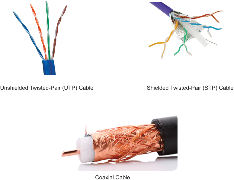
Figure 4-11 Types of Copper Cable
Unshielded Twisted-Pair (UTP) (4.3.3)
Unshielded twisted-pair (UTP) cabling is the most common networking medium. UTP cabling, terminated with RJ-45 connectors, is used for interconnecting network hosts with intermediary networking devices, such as switches and routers.
In LANs, UTP cable consists of four pairs of color-coded wires that have been twisted together and then encased in a flexible plastic sheath that protects against minor physical damage, as shown in Figure 4-12. The twisting of wires helps protect against signal interference from other wires.
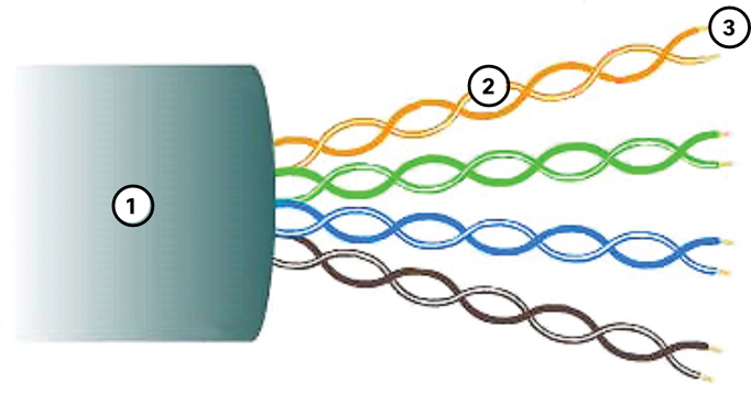
Figure 4-12 UTP Cable
The color codes identify the individual pairs and wires and aid in cable termination.
The numbers in Figure 4-12 identify some key features of UTP cable:
The outer jacket protects the copper wires from physical damage.
Twisted pairs protect the signal from interference.
Color-coded plastic insulation electrically isolates wires from each other and identifies the pairs.
Shielded Twisted-Pair (STP) (4.3.4)
Shielded twisted-pair (STP) provides better noise protection than UTP cabling. However, compared to UTP cable, STP cable is significantly more expensive and difficult to install. Like UTP cable, STP uses RJ-45 connectors.
STP cables combine the techniques of shielding to counter EMI and RFI and wire twisting to counter crosstalk. To gain the full benefit of the shielding, STP cables are terminated with special shielded STP data connectors. If the cable is improperly grounded, the shield may act as an antenna and pick up unwanted signals.
The STP cable shown in Figure 4-13 uses four pairs of wires, each wrapped in a foil shield, and then wrapped in an overall metallic braid or foil.
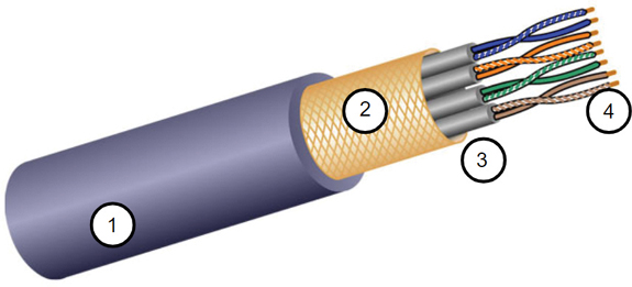
Figure 4-13 STP Cable
The numbers in Figure 4-13 identify some key features of STP cable:
Outer jacket
Braided or foil shield
Foil shields
Twisted pairs
Coaxial Cable (4.3.5)
Coaxial cable, or coax for short, gets its name from the fact that there are two conductors that share the same axis. As shown in Figure 4-14, coaxial cable consists of the following:
The entire cable is covered with a cable jacket to prevent minor physical damage.
The insulating material is surrounded by a woven copper braid, or metallic foil, that acts as the second wire in the circuit and as a shield for the inner conductor. This second layer, or shield, also reduces the amount of outside electromagnetic interference.
A layer of flexible plastic insulation surrounds a copper conductor.
A copper conductor is used to transmit the electronic signals.
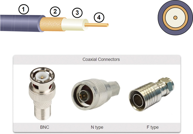
Figure 4-14 Coaxial Cable and Connectors
Different types of connectors are used with coax cable. Figure 4-14 shows the Bayonet Neill–Concelman (BNC), N type, and F type connectors.
The numbers in Figure 4-14 identify some key features of coaxial cable:
Outer jacket
Braided copper shielding
Plastic insulation
Copper conductor
Although UTP cable has essentially replaced coaxial cable in modern Ethernet installations, the coaxial cable design is used in the following situations:
Wireless installations: Coaxial cables attach antennas to wireless devices. The coaxial cable carries radio frequency (RF) energy between the antennas and the radio equipment.
Cable internet installations: Cable service providers provide internet connectivity to their customers by replacing portions of the coaxial cable and supporting amplification elements with fiber-optic cable. However, the wiring inside the customer’s premises is still coax cable.
Check Your Understanding—Copper Cabling (4.3.6)
Refer to the online course to complete this activity.
UTP Cabling (4.4)
Copper media has some inherent issues. Twisting the internal pairs of the copper media, as is done in UTP, is a low-cost solution to improve cabling performance. This section further explores UTP cabling.
Properties of UTP Cabling (4.4.1)
In the previous section, you learned a bit about unshielded twisted-pair (UTP) copper cabling. Because UTP cabling is the standard for use in LANs, this section goes into detail about its advantages and limitations, as well as what can be done to avoid problems.
When used as a networking medium, UTP cabling consists of four pairs of color-coded copper wires that have been twisted together and then encased in a flexible plastic sheath. Its small size can be advantageous during installation.
UTP cable does not use shielding to counter the effects of EMI and RFI. Instead, cable designers have discovered other ways to limit the negative effect of crosstalk:
Cancellation: Designers now pair wires in a circuit. When two wires with magnetic fields exactly opposite each other are placed close together in an electrical circuit, the two magnetic fields cancel each other out and also cancel out any outside EMI and RFI signals.
Varying the number of twists per wire pair: To further enhance the cancellation effect of paired circuit wires, designers vary the number of twists of each wire pair in a cable. UTP cable must follow precise specifications governing how many twists or braids are permitted per meter (3.28 feet) of cable. Notice in Figure 4-15 that the bottom pair (which is orange/orange white, though you can’t see that in this book) is twisted less than the pair just above it (which is a blue/blue white pair). Each colored pair is twisted a different number of times.
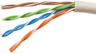
Figure 4-15 Different Number of Twists in Each UTP Pair
UTP cable relies solely on the cancellation effect produced by the twisted wire pairs to limit signal degradation and effectively provide self-shielding for wire pairs within the network media.
UTP Cabling Standards and Connectors (4.4.2)
UTP cabling conforms to the standards established jointly by the TIA/EIA. Specifically, TIA/EIA-568 stipulates the commercial cabling standards for LAN installations and is the standard most commonly used in LAN cabling environments. Some of the elements defined are as follows:
Cable types
Cable lengths
Connectors
Cable termination
Methods of testing cable
The electrical characteristics of copper cabling are defined by the Institute of Electrical and Electronics Engineers (IEEE). IEEE rates UTP cabling according to its performance. Cables are placed into categories based on their ability to carry various bandwidth rates. For example, Category 5 cable is used commonly in 100BASE-TX Fast Ethernet installations. Other categories include Enhanced Category 5 cable, Category 6, and Category 6a.
Cables in higher categories are designed and constructed to support higher data rates. As new gigabit speed Ethernet technologies are being developed and adopted, Category 5e is now the minimally acceptable cable type, with Category 6 being the recommended type for new building installations.
Figure 4-16 shows three categories of UTP cable:
Category 3 was originally used for voice communication over voice lines but later began to be used for data transmission.
Category 5 and 5e are used for data transmission. Category 5 supports 100 Mbps, and Category 5e supports 1000 Mbps.
Category 6 has an added separator between each wire pair to support higher speeds. Category 6 supports up to 10 Gbps.
Category 6a is similar to Category 6 with improved crosstalk characteristics to allow for longer distances.
Category 7 also supports 10 Gbps.
Category 8 supports 40 Gbps.
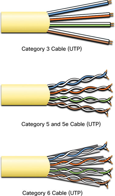
Figure 4-16 Categories of UTP
Some manufacturers are making cables exceeding the TIA/EIA Category 6a specifications and refer to these as Category 7.
UTP cable is usually terminated with RJ-45 connectors. The TIA/EIA-568 standard describes the wire color codes and pin assignments (pinouts) for Ethernet cables.
As shown in Figure 4-17, the RJ-45 connector is the male component, crimped at the end of the cable.
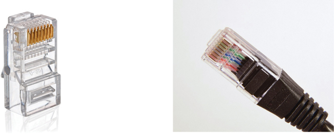
Figure 4-17 RJ-45 UTP Plugs
The socket, shown in Figure 4-18, is the female component of a network device, wall, cubicle partition outlet, or patch panel.
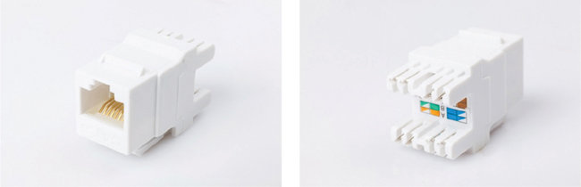
Figure 4-18 RJ-45 UTP Sockets
When terminated improperly, a cable is a potential source of physical layer performance degradation. Figure 4-19 shows an example of a badly terminated UTP cable. This bad connector has wires that are exposed, untwisted, and not entirely covered by the sheath.
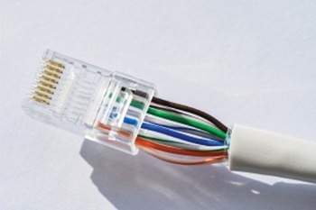
Figure 4-19 Poorly Terminated UTP Cable
Figure 4-20 shows a properly terminated UTP cable. It is a good connector with wires that are untwisted only to the extent necessary to attach the connector.
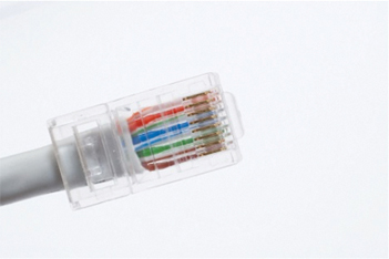
Figure 4-20 Properly Terminated UTP Cable
Note
Improper cable termination can impact transmission performance.
Straight-Through and Crossover UTP Cables (4.4.3)
Different situations may require UTP cables to be wired according to different wiring conventions. This means that the individual wires in the cable have to be connected in different orders to different sets of pins in the RJ-45 connectors.
The following are the main cable types that are created by using specific wiring conventions:
Ethernet straight-through: This is the most common type of networking cable, commonly used to interconnect a host to a switch and a switch to a router.
Ethernet crossover: This cable is used to interconnect similar devices—for example, to connect a switch to a switch, a host to a host, or a router to a router. However, crossover cables are now considered legacy as NICs use medium-dependent interface crossover (auto-MDIX) to automatically detect the cable type and make the internal connection.
Note
Another type of cable is a rollover cable, which is a Cisco-proprietary cable. It is used to connect a workstation to a router or switch console port.
Incorrectly using a crossover or straight-through cable between devices may not damage the devices, but connectivity and communication between the devices will not take place. This is a common error, and checking that the device connections are correct should be the first troubleshooting action if connectivity is not achieved.
Figure 4-21 identifies the individual wire pairs for the T568A and T568B standards.
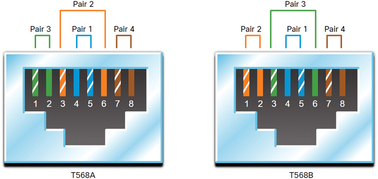
Figure 4-21 T568A and T568B Standards
Table 4-2 shows the UTP cable type, related standards, and typical applications of these cables.
Table 4-2 Cable Types and Standards
Cable Type |
Standard |
Application |
Ethernet straight-through |
Both ends T568A or both ends T568B |
Connects a network host to a network device such as a switch or hub |
Ethernet crossover |
One end T568A, other end T568B |
Connects two network hosts Connects two network intermediary devices (switch to switch or router to router) |
Rollover |
Cisco proprietary |
Connects a workstation serial port to a router console port, using an adapter |
Activity—Cable Pinouts (4.4.4)
For this activity, correctly order the wire colors to a TIA/EIA cable pinout. Select a wire sheath color by clicking it. Then click a wire to apply that sheath to it. Refer to the online course to complete this activity.
Fiber-Optic Cabling (4.5)
Networking media selection is being driven by the growing needs for network bandwidth. The distance and performance of fiber-optic cable make it a good media choice for supporting these network needs. This section examines the characteristics of fiber-optic cabling use in data networks.
Properties of Fiber-Optic Cabling (4.5.1)
As you have learned, fiber-optic cabling is a type of cabling used in many networks today. Because it is expensive, it is not as commonly used at the various types of copper cabling. But fiber-optic cabling has certain properties that make it the best option in certain situations, as discussed in this section.
Optical fiber cable transmits data over longer distances and at higher bandwidths than any other networking media. Fiber-optic cable can transmit signals with less attenuation than copper wire, and it is completely immune to EMI and RFI. Optical fiber is commonly used to interconnect network devices.
Optical fiber contains a flexible but extremely thin, transparent strand of very pure glass, not much bigger than a human hair. Bits are encoded on the fiber as light impulses. The fiber-optic cable acts as a waveguide, or “light pipe,” to transmit light between the two ends with minimal loss of signal.
As an analogy, consider an empty paper towel roll with the inside coated like a mirror. Imagine that it is 1000 meters in length, and a small laser pointer is used to send Morse code signals at the speed of light. Essentially, that is how a fiber-optic cable operates, except that it is smaller in diameter and uses sophisticated light technologies.
Types of Fiber Media (4.5.2)
Fiber-optic cables are broadly classified into two types: single-mode fiber (SMF) and multimode fiber (MMF).
Single-Mode Fiber
SMF consists of a very small core and uses expensive laser technology to send a single ray of light, as shown in Figure 4-22. SMF is popular in long-distance situations spanning hundreds of kilometers, such as those required in long-haul telephony and cable TV applications.
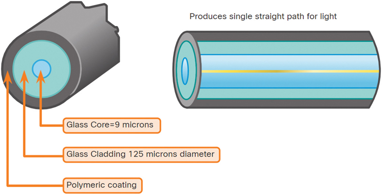
Figure 4-22 Single-Mode Fiber
Multimode Fiber
MMF consists of a larger core and uses LED emitters to send light pulses. Specifically, light from an LED enters the multimode fiber at different angles, as shown in Figure 4-23. It is popular in LANs because they can be powered by low-cost LEDs. It provides bandwidth up to 10 Gbps over link lengths of up to 550 meters.
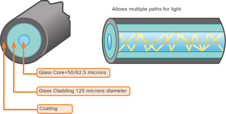
Figure 4-23 Multimode Fiber
One of the main differences between MMF and SMF is the amount of dispersion. Dispersion refers to the spreading out of a light pulse over time. Increased dispersion means increased loss of signal strength. MMF has greater dispersion than SMF; this is why MMF can travel only up to 550 meters before signal loss occurs.
Fiber-Optic Cabling Usage (4.5.3)
Fiber-optic cabling is now being used in four types of industry:
Enterprise networks: Fiber is used for backbone cabling applications and for interconnecting infrastructure devices.
Fiber-to-the-home (FTTH): Fiber is used to provide always-on broadband services to homes and small businesses.
Long-haul networks: Service providers use fiber to connect countries and cities.
Submarine cable networks: Fiber is used to provide reliable high-speed, high-capacity solutions capable of surviving in harsh undersea environments at up to transoceanic distances. Search the internet for “submarine cables telegeography map” to view various maps online.
Our focus in this book is the use of fiber within the enterprise.
Fiber-Optic Connectors (4.5.4)
A fiber-optic connector terminates the end of an optical fiber. A variety of fiber-optic connectors are available. The main differences among them are their dimensions and the methods of coupling. Businesses decide on the types of connectors that will be used, based on their equipment.
Note
Some switches and routers have ports that support fiber-optic connectors through a small form-factor pluggable (SFP) transceiver. Search the internet for various types of SFPs.
The straight-tip (ST) connector (see Figure 4-24) was one of the first connector types used. The connector locks securely with a “twist-on/twist-off” bayonet-style mechanism.
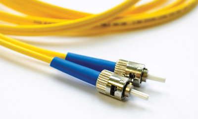
Figure 4-24 Straight-Tip (ST) Connectors
Subscriber connector (SC) connectors (see Figure 4-25) are sometimes referred to as square connectors or standard connectors. They are widely adopted LAN and WAN connectors that use a push/pull mechanism to ensure positive insertion. This connector type is used with multimode and single-mode fiber.
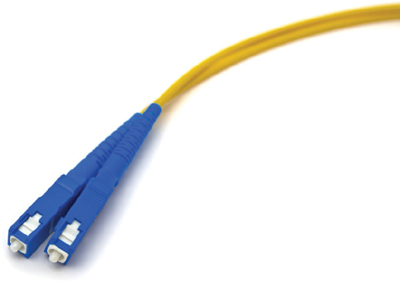
Figure 4-25 Subscriber Connector (SC) Connectors
The Lucent Connector (LC) simplex connector (see Figure 4-26) is a smaller version of the SC connector. LC connectors are sometimes called little connectors or local connectors, and their popularity is quickly growing due to their smaller size.
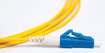
Figure 4-26 Lucent Connector (LC) Simplex Connector
A duplex multimode LC connector (see Figure 4-27) is similar to an LC simplex connector but uses a duplex connector.
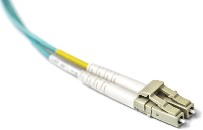
Figure 4-27 Duplex Multimode LC Connector
Until recently, light could travel in only one direction over optical fiber. Two fibers were required to support full-duplex operation. Therefore, two optical fiber cables needed to be bundled with fiber-optic patch cables and terminated with a pair of standard, single-fiber connectors. Some fiber connectors accept both the transmitting and receiving fibers in a single connector known as a duplex connector (shown in Figure 4-27). BX standards such as 100BASE-BX use different wavelengths for sending and receiving over a single fiber.
Fiber Patch Cords (4.5.5)
Fiber patch cords are required for interconnecting infrastructure devices. The use of color distinguishes between single-mode and multimode patch cords. A single-mode fiber cable has a yellow jacket, and a multimode fiber cable has an orange (or aqua) jacket.
Figure 4-28 shows four types of fiber patch cords.
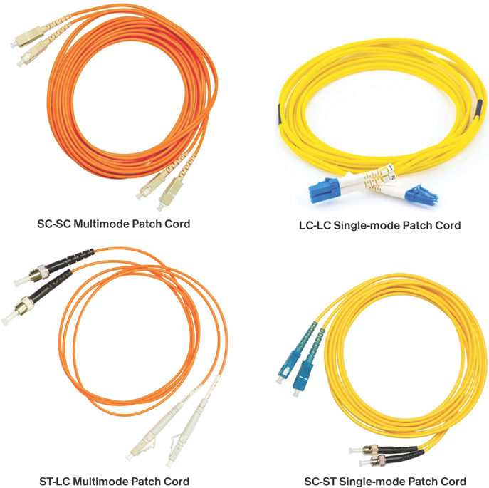
Figure 4-28 Fiber Patch Cords
Note
A fiber cable should be protected with a small plastic cap when not in use.
Fiber Versus Copper (4.5.6)
There are many advantages to using fiber-optic cable compared to using copper cable. Table 4-3 highlights some of the differences between these cable types.
Table 4-3 UTP and Fiber-Optic Cabling Comparison
Implementation Issue |
UTP Cabling |
Fiber-Optic Cabling |
Bandwidth supported |
10 Mbps–10 Gbps |
10 Mbps–100 Gbps |
Distance |
Relatively short (1–100 meters) |
Relatively long (1–100,000 meters) |
Immunity to EMI and RFI |
Low |
High (completely immune) |
Immunity to electrical hazards |
Low |
High (completely immune) |
Media and connector costs |
Lowest |
Highest |
Installation skills required |
Lowest |
Highest |
Safety precautions |
Lowest |
Highest |
At present, in most enterprise environments, optical fiber is primarily used as backbone cabling for high-traffic, point-to-point connections between data distribution facilities. It is also used to interconnect buildings in multi-building campuses. Because fiber-optic cables do not conduct electricity and have low signal loss, they are well suited for these uses.
Check Your Understanding—Fiber-Optic Cabling (4.5.7)
Refer to the online course to complete this activity.
Wireless Media (4.6)
As more mobile devices are being used, wireless networking is growing in demand. This section explores wireless media characteristic and uses.
Properties of Wireless Media (4.6.1)
You might be reading this book or taking the accompanying course using a tablet or a smartphone. This is only possible due to the use of wireless media to connect to the physical layer of a network.
Wireless media carry electromagnetic signals that represent the binary digits of data communications using radio wave or microwave frequencies.
Wireless media provide the greatest mobility options of all media. Wireless is now the primary way users connect to home and enterprise networks, and the number of wireless-enabled devices continues to increase.
These are some of the limitations of wireless:
Coverage area: Wireless data communication technologies work well in open environments. However, certain construction materials used in buildings and structures, as well as the local terrain, can limit the effective coverage.
Interference: Wireless is susceptible to interference and can be disrupted by such common devices as household cordless phones, some types of fluorescent lights, microwave ovens, and other wireless communications.
Security: Wireless communication coverage requires no access to a physical strand of cable. Therefore, devices and users not authorized for access to the network can gain access to the transmission. Network security is a major component of wireless network administration.
Shared medium: WLANs operate in half-duplex, which means only one device can send or receive at a time. The wireless medium is shared among all wireless users. Many users accessing the WLAN simultaneously results in reduced bandwidth for each user.
Although wireless is increasing in popularity for desktop connectivity, copper and fiber are the most popular physical layer media for deployment of intermediary network devices, such as routers and switches.
Types of Wireless Media (4.6.2)
The IEEE and telecommunications industry standards for wireless data communications cover both the data link and physical layers. In each of these standards, physical layer specifications are applied to areas such as the following:
Data-to-radio signal encoding
Frequency and power of transmission
Signal reception and decoding requirements
Antenna design and construction
These are the wireless standards:
Wi-Fi (IEEE 802.11): Wi-Fi is a wireless LAN (WLAN) technology that uses a contention-based protocol known as Carrier Sense Multiple Access/Collision Avoidance (CSMA/CA). The wireless NIC must first listen before transmitting to determine if the radio channel is clear. If another wireless device is transmitting, then the NIC must wait until the channel is clear. Wi-Fi is a trademark of the Wi-Fi Alliance. Wi-Fi is used with certified WLAN devices based on the IEEE 802.11 standards.
Bluetooth (IEEE 802.15): Bluetooth is a wireless personal area network (WPAN) standard that uses a device pairing process to communicate over distances from 1 to 100 meters.
WiMAX (IEEE 802:16): Worldwide Interoperability for Microware Access (WiMAX) is a wireless standard that uses a point-to-multipoint topology to provide wireless broadband access.
Zigbee (IEEE 802.15.4): Zigbee is a specification used for low-data-rate, low-power communications. It is intended for applications that require short range, low data rates, and long battery life. Zigbee is typically used in industrial and Internet of Things (IoT) environments, such as for wireless light switches and medical device data collection.
Note
Other wireless technologies, such as cellular and satellite communications, can also provide data network connectivity. However, these wireless technologies are beyond the scope of this chapter.
Wireless LAN (4.6.3)
A common wireless data implementation involves enabling devices to connect wirelessly over a LAN. In general, a WLAN requires the following network devices:
Wireless access points (APs): Wireless APs concentrate the wireless signals from users and connect to the existing copper-based network infrastructure, such as Ethernet. Home and small-business wireless routers integrate the functions of a router, switch, and access point into one device, as shown in Figure 4-29.
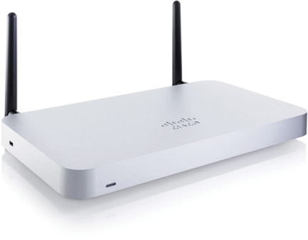
Figure 4-29 Cisco Meraki MX64W
Wireless NIC adapters: These adapters provide wireless communication capability to network hosts.
As the technology has developed, a number of WLAN Ethernet-based standards have emerged. When purchasing wireless devices, it is important to ensure compatibility and interoperability in a network.
The benefits of wireless data communications technologies are evident—especially the savings on costly premises wiring and the convenience of host mobility. However, network administrators must develop and apply stringent security policies and processes to protect WLANs from unauthorized access and damage.
Check Your Understanding—Wireless Media (4.6.4)
Refer to the online course to complete this activity.
Packet Tracer—Connect a Wired and Wireless LAN (4.6.5)

When working in Packet Tracer, a lab environment, or a corporate setting, you should know how to select the appropriate cable and know how to properly connect devices. In this activity you will examine device configurations in Packet Tracer, select the proper cable based on the configuration, and connect the devices. In this activity you will also explore the physical view of a network in Packet Tracer.
Lab—View Wired and Wireless NIC Information (4.6.6)
In this lab, you will complete the following objectives:
Part 1: Identify and Work with PC NICs
Part 2: Identify and Use the System Tray Network Icons
Packet Tracer—Connect the Physical Layer (4.7.1)
In this activity, you will explore the different options available on internetworking devices. You will also be required to determine which options provide the necessary connectivity when connecting multiple devices. Finally, you will add the correct modules and connect the devices.
Summary (4.7)
The following is a summary of the topics in the chapter and their corresponding online modules.
Purpose of the Physical Layer
Before any network communications can occur, a physical connection to a local network must be established. A physical connection can be a wired connection using a cable or a wireless connection using radio waves. A network interface card (NIC) connects a device to a network. Ethernet NICs are used for wired connections, and WLAN (wireless local-area network) NICs are used for wireless. The OSI physical layer provides the means to transport the bits that make up a data link layer frame across the network media. The physical layer accepts a complete frame from the data link layer and encodes it as a series of signals that are transmitted onto the local media. The encoded bits that comprise a frame are received by either an end device or an intermediary device.
Physical Layer Characteristics
The physical layer consists of electronic circuitry, media, and connectors developed by engineers. The physical layer standards address three functional areas: physical components, encoding, and signaling. Bandwidth is the capacity at which a medium can carry data. Digital bandwidth measures the amount of data that can flow from one place to another in a given amount of time. Throughput is a measure of the transfer of bits across the media over a given period of time and is usually lower than bandwidth. Latency refers to the amount of time, including delays, for data to travel from one given point to another. Goodput is a measure of usable data transferred over a given period of time. The physical layer produces the representation and groupings of bits for each type of media as follows:
Copper cable: The signals are patterns of electrical pulses.
Fiber-optic cable: The signals are patterns of light.
Wireless: The signals are patterns of microwave transmissions.
Copper Cabling
Networks use copper media because it is inexpensive and easy to install, and it has low resistance to electrical current. However, copper media is limited by distance and signal interference. The timing and voltage values of the electrical pulses are also susceptible to interference from two sources: EMI and crosstalk. Three types of copper cabling are UTP, STP, and coaxial cable (coax). UTP has an outer jacket to protect the copper wires from physical damage, twisted pairs to protect the signal from interference, and color-coded plastic insulation that electrically isolates wires from each other and identifies each pair. STP cable uses four pairs of wires, each wrapped in a foil shield, and the four pairs are then wrapped in an overall metallic braid or foil. Coaxial cable, or coax for short, gets its name from the fact that it has two conductors that share the same axis. Coax is used to attach antennas to wireless devices. Cable internet providers use coax inside their customers’ premises.
UTP Cabling
UTP cabling consists of four pairs of color-coded copper wires that have been twisted together and then encased in a flexible plastic sheath. UTP cable does not use shielding to counter the effects of EMI and RFI. Instead, cable designers have discovered other ways they can limit the negative effect of crosstalk: by using cancellation and by varying the number of twists per wire pair. UTP cabling conforms to the standards established jointly by the TIA/EIA. The electrical characteristics of copper cabling are defined by the Institute of Electrical and Electronics Engineers (IEEE). UTP cable is usually terminated with RJ-45 connectors. The main cable types created by using specific wiring conventions are Ethernet straight-through and Ethernet crossover. Cisco has a proprietary UTP cable called a rollover cable that connects a workstation to a router console port.
Fiber-Optic Cabling
Optical fiber cable transmits data over longer distances and at higher bandwidths than any other networking media. Fiber-optic cable can transmit signals with less attenuation than copper wire and is completely immune to EMI and RFI. Optical fiber contains a flexible but extremely thin, transparent strand of very pure glass, not much bigger than a human hair. Bits are encoded on the fiber as light impulses. Fiber-optic cabling is now being used in enterprise networks, FTTH, long-haul networks, and submarine cable networks. There are four types of fiber-optic connectors: ST, SC, LC, and duplex multimode LC. Fiber-optic patch cords include SC-SC multimode, LC-LC single-mode, ST-LC multimode, and SC-ST single-mode. In most enterprise environments, optical fiber is primarily used as backbone cabling for high-traffic point-to-point connections between data distribution facilities and for interconnecting buildings in multi-building campuses.
Wireless Media
Wireless media carry electromagnetic signals that represent the binary digits of data communications using radio wave or microwave frequencies. Wireless does have some limitations, including coverage area, interference, security, and the problems that occur with any shared medium. Wireless standards include Wi-Fi (IEEE 802.11), Bluetooth (IEEE 802.15), WiMAX (IEEE 802.16), and Zigbee (IEEE 802.15.4). A wireless LAN (WLAN) requires a wireless AP and wireless NIC adapters.
Practice
The following activities provide practice with the topics introduced in this chapter. The lab is available in the companion Introduction to Networks Labs & Study Guide (CCNAv7) (ISBN 9780136634454). The Packet Tracer activity instructions are also provided in the Labs & Study Guide. The PKA files are available in the online course.
Lab
Lab 4.6.6: View Wired and Wireless NIC Information
Packet Tracer Activities
Packet Tracer 4.6.5: Connect a Wired and Wireless LAN
Packet Tracer 4.7.1: Connect the Physical Layer
Check Your Understanding Questions
Complete all the review questions listed here to test your understanding of the topics and concepts in this chapter. The appendix “Answers to ‘Check Your Understanding’ Questions” lists the answers.
1. What is the purpose of the OSI physical layer?
controlling access to media
transmitting bits across the local media
performing error detection on received frames
exchanging frames between nodes over physical network media
2. Why are two strands of fiber used for a single fiber-optic connection?
The two strands allow the data to travel for longer distances without degrading.
The two strands prevent crosstalk from causing interference on the connection.
The two strands increase the speed at which the data can travel.
The two strands allow for full-duplex connectivity.
3. Which of the following describes crosstalk?
the distortion of a network signal due to fluorescent lighting
the distortion of a transmitted message due to signals carried in adjacent wires
the weakening of a network signal over long cable lengths
the loss of wireless signal over excessive distance from an access point
4. Which procedure is used to reduce the effect of crosstalk in copper cables?
requiring proper grounding connections
twisting opposing-circuit wire pairs together
wrapping a bundle of wires with metallic shielding
designing a cable infrastructure to avoid crosstalk interference
avoiding sharp bends during installation
5. Which type of UTP cable is used to connect a PC to a switch port?
console
rollover
crossover
straight-through
6. What is the definition of bandwidth?
the speed of bits across media over a given period of time
the speed at which bits travel on a network
the amount of data that can flow in a given amount of time
the measure of usable data transferred over a given period of time
7. Which statement correctly describes frame encoding?
It uses the characteristic of one wave to modify another wave.
It transmits data signals along with a clock signal that occurs at evenly spaced time durations.
It generates the electrical, optical, or wireless signals that represent the binary numbers of the frame.
It converts bits into a predefined code in order to provide a predictable pattern to help distinguish data bits from control bits.
8. Which of the following is a characteristic of UTP cabling?
cancellation
cladding
immunity to electrical hazards
woven copper braid or metallic foil
9. A wireless LAN is being deployed inside the new one-room office that is occupied by the park ranger. The office is located at the highest part of the national park. After network testing is complete, the technicians report that the wireless LAN signal is occasionally affected by some type of interference. What is a possible cause of the signal distortion?
the microwave oven
the large number of trees surrounding the office
the elevated location where the wireless LAN was installed
the number of wireless devices that are used in the wireless LAN
10. What is indicated by the term throughput?
the guaranteed data transfer rate offered by an ISP
the capacity of a particular medium to carry data
the measure of the usable data transferred across media over a given period of time
the measure of bits transferred across media over a given period of time
11. What is one advantage of using fiber-optic cabling rather than copper cabling?
It is usually cheaper than copper cabling.
It can be installed around sharp bends.
It is easier to terminate and install than copper cabling.
It is able to carry signals much farther than copper cabling.
12. Which standards organization oversees development of wireless LAN standards?
IANA
IEEE
ISO
TIA
13. A network administrator is designing a new network infrastructure that includes both wired and wireless connectivity. In which situation would a wireless connection be recommended?
The end-user device has only an Ethernet NIC.
The end-user device requires a dedicated connection due to performance requirements.
The end-user device needs mobility when connecting to the network.
The end-user device area has a high concentration of RFI.
14. A network administrator is troubleshooting connectivity issues on a server. Using a tester, the administrator notices that the signals generated by the server NIC are distorted and not usable. In which layer of the OSI model does the error occur?
presentation layer
network layer
physical layer
data link layer
15. What type of cable is used to connect a workstation serial port to a Cisco router console port?
crossover
rollover
straight-through
coaxial