Chapter 8
Network Layer
Objectives
Upon completion of this chapter, you will be able to answer the following questions:
How does the network layer use IP protocols for reliable communications?
What is the role of the major header fields in the IPv4 packet?
What is the role of the major header fields in the IPv6 packet?
How do network devices use routing tables to direct packets to a destination network?
What is the function of fields in the routing table of a router?
Key Terms
This chapter uses the following key terms. You can find the definitions in the glossary at the end of the book.
maximum transmission unit (MTU) page 274
Internet Control Message Protocol (ICMP) page 275
Network Address Translation (NAT) page 277
Introduction (8.0)
By now you might have noticed that the modules in this course—and the chapters in this book—are progressing from the bottom up through the OSI model layers. This chapter focuses on the network layer of the OSI model, which is where communication protocols and routing protocols operate. Say you want to send an email to a friend who lives in another city—or even another country. This person is not on the same network as you. A simple switched network cannot get your message any further than the end of that network. You need some help to keep the message moving along the path to your friend’s end device. To send an email (a video, or a file, and so on) to anyone who is not on your local network, you must have access to routers. To access routers, you must use network layer protocols. To help you visualize these processes, this module contains two Wireshark activities. Enjoy!
Network Layer Characteristics (8.1)
This section introduces the protocols and functions of the network layer. The function of the network layer is to facilitate the transport of data from one network to another. This section introduces the elementary functions of the network layer.
The Network Layer (8.1.1)
The network layer, or OSI Layer 3, provides services that allow end devices to exchange data across networks. As shown in Figure 8-1, IP version 4 (IPv4) and IP version 6 (IPv6) are the principal network layer communication protocols. Other network layer protocols include routing protocols such as Open Shortest Path First (OSPF) and messaging protocols such as Internet Control Message Protocol (ICMP).
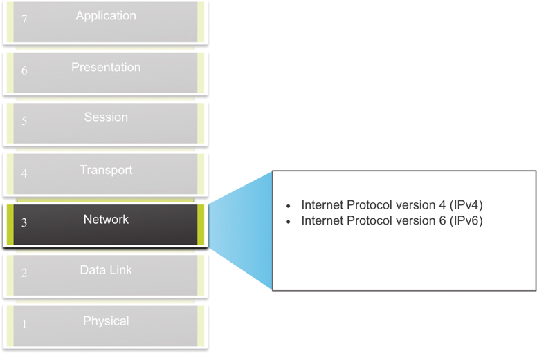
Figure 8-1 Network Layer of the OSI Model
To accomplish end-to-end communication across network boundaries, network layer protocols perform four basic operations:
Addressing of end devices: End devices must be configured with unique IP addresses for identification on the network.
Encapsulation: The network layer encapsulates the protocol data unit (PDU) from the transport layer into a packet. The encapsulation process adds IP header information, such as the IP address of the source (sending) and destination (receiving) hosts. The encapsulation process is performed by the source of the IP packet.
Routing: The network layer provides services to direct the packets to a destination host on another network. To travel to other networks, the packet must be processed by a router. The role of the router is to select the best path and direct packets toward the destination host in a process known as routing. A packet may cross many routers before reaching the destination host. Each router a packet crosses to reach the destination host is called a hop.
De-encapsulation: When a packet arrives at the network layer of the destination host, the host checks the IP header of the packet. If the destination IP address within the header matches its own IP address, the IP header is removed from the packet. After the packet is de-encapsulated by the network layer, the resulting Layer 4 PDU is passed up to the appropriate service at the transport layer. The de-encapsulation process is performed by the destination host of the IP packet.
Unlike the transport layer (OSI Layer 4), which manages the data transport between the processes running on each host, network layer communication protocols (that is, IPv4 and IPv6) specify the packet structure and processing used to carry the data from one host to another host. Operating without regard to the data carried in each packet allows the network layer to carry packets for multiple types of communications between multiple hosts.
IP Encapsulation (8.1.2)
IP encapsulates the segment or other data from the transport layer (the layer just above the network layer) by adding an IP header. The IP header is used to deliver a packet to the destination host.
Figure 8-2 illustrates how the transport layer PDU is encapsulated by the network layer PDU to create an IP packet.
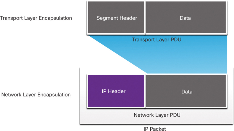
Figure 8-2 Transport Layer PDU Encapsulated in the Network Layer
The process of encapsulating data layer by layer enables the services at the different layers to develop and scale without affecting the other layers. This means the transport layer segments can be readily packaged by IPv4 or IPv6 or by any new protocol that might be developed in the future.
The IP header is examined by Layer 3 devices (that is, routers and Layer 3 switches) as it travels across a network to its destination. It is important to note that the IP addressing information remains the same from the time the packet leaves the source host until it arrives at the destination host, except when translated by a device performing Network Address Translation (NAT) for IPv4.
Note
NAT is discussed in Chapters 8 and 12.
Routers implement routing protocols to route packets between networks. The packet forwarding performed by these intermediary devices involves examining the network layer addressing in the packet header. In all cases, the data portion of the packet—that is, the encapsulated transport layer PDU or other data—remains unchanged during the network layer processes.
Characteristics of IP (8.1.3)
IP was designed as a protocol with low overhead. It provides only the functions that are necessary to deliver a packet from a source to a destination over an interconnected system of networks. The protocol was not designed to track and manage the flow of packets. These functions, if required, are performed by other protocols at other layers, primarily TCP at Layer 4.
These are the basic characteristics of IP:
Connectionless: There is no connection with the destination established before sending data packets.
Best effort: IP is inherently unreliable because packet delivery is not guaranteed.
Media independent: Operation is independent of the medium (that is, copper, optical fiber, or wireless) carrying the data.
Connectionless (8.1.4)
IP is connectionless, meaning that no dedicated end-to-end connection is created by IP before data is sent. Connectionless communication is conceptually similar to sending a letter to someone without notifying the recipient in advance. Figure 8-3 illustrates this key point.
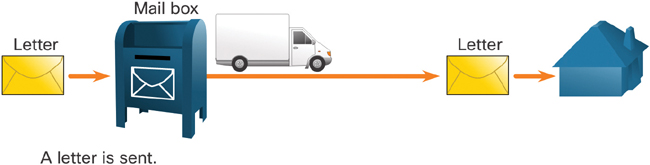
Figure 8-3 Letter Analogy of Connectionless Communication
Connectionless data communications work on the same principle. As shown in Figure 8-4, IP requires no initial exchange of control information to establish an end-to-end connection before packets are forwarded.
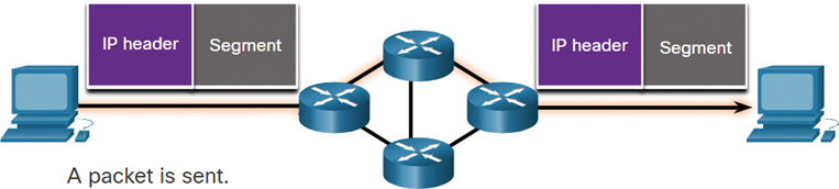
Figure 8-4 IP is Connectionless
Best Effort (8.1.5)
IP does not require additional fields in the header to maintain an established connection. This process greatly reduces the overhead of IP. However, with no pre-established end-to-end connection, senders are unaware whether destination devices are present and functional when sending packets; they also are not aware of whether the destination receives a packet or whether a destination device is able to access and read a packet.
IP does not guarantee that all packets that are sent are, in fact, received. Figure 8-5 illustrates the unreliable, or best-effort delivery, characteristic of IP. As an unreliable network layer protocol, IP does not guarantee that all sent packets will be received. Other protocols manage the process of tracking packets and ensuring their delivery.
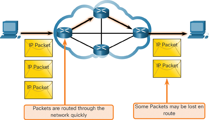
Figure 8-5 Best-Effort Delivery
Media Independent (8.1.6)
Unreliable means that IP does not have the capability to manage and recover from undelivered or corrupt packets. This is because while IP packets are sent with information about the location of delivery, they do not contain information that can be processed to inform the sender about whether delivery was successful. Packets may arrive at the destination corrupted, out of sequence, or not at all. IP provides no capability for packet retransmissions if errors occur.
If out-of-order packets are delivered, or if packets are missing, then applications using the data, or upper-layer services, must resolve these issues. This allows IP to function very efficiently. In the TCP/IP protocol suite, reliability is the role of TCP at the transport layer.
IP operates independently of the media that carry the data at lower layers of the protocol stack. As shown in Figure 8-6, IP packets can be communicated as electronic signals over copper cable, as optical signals over fiber, or wirelessly as radio signals.
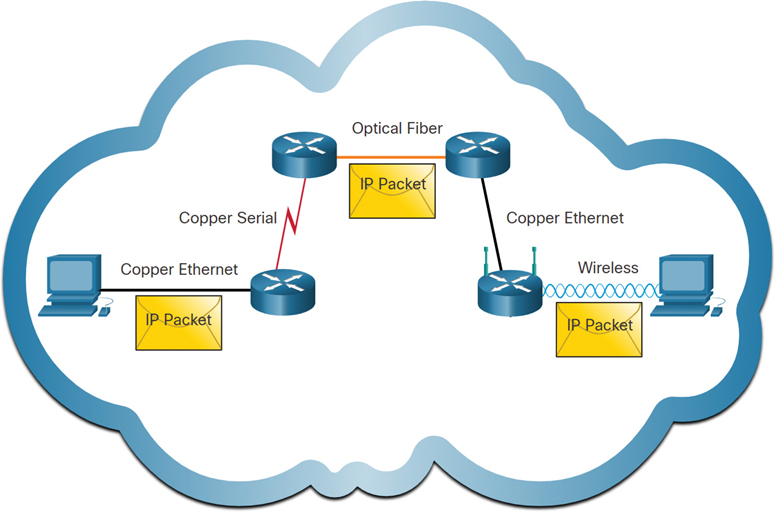
Figure 8-6 IP Packets Cross Multiple Media Types
The OSI data link layer is responsible for preparing an IP packet for transmission over the communications medium. This means that the delivery of IP packets is not limited to any particular medium.
There is, however, one major characteristic of the media that the network layer considers: the maximum size of the PDU that each medium can transport. This characteristic is referred to as the maximum transmission unit (MTU). Part of the control communication between the data link layer and the network layer is the establishment of a maximum size for a packet. The data link layer passes the MTU value up to the network layer. The network layer then determines how large packets can be.
In some cases, an intermediate device, usually a router, must split up an IPv4 packet when forwarding it from one medium to another medium with a smaller MTU. This process is called fragmenting the packet, or fragmentation. Fragmentation causes latency. IPv6 packets cannot be fragmented by the router.
Check Your Understanding—IP Characteristics (8.1.7)

Refer to the online course to complete this activity.
IPv4 Packet (8.2)
The ability to provide the end-to-end transfer of data by the network layer is based on the content and interpretation of the Layer 3 header. This section examines the structure and contents of the IPv4 header.
IPv4 Packet Header (8.2.1)
IPv4 is one of the primary network layer communication protocols. The IPv4 header of a packet is used to ensure that this packet is delivered to its next stop on the way to its destination end device.
An IPv4 packet header consists of fields containing important information about the packet. These fields contain binary numbers that are examined by the Layer 3 process.
IPv4 Packet Header Fields (8.2.2)
The binary values of each IPv4 packet header field identify various settings of the IP packet. Protocol header diagrams, which are read left to right and top to bottom, provide visuals to refer to when discussing protocol fields. The IP protocol header diagram in Figure 8-7 identifies the fields of an IPv4 packet.
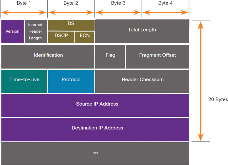
Figure 8-7 IPv4 Packet Header Fields
Significant fields in the IPv4 header include the following:
Version: This field contains a 4-bit binary value set to 0100 that identifies this as an IPv4 packet.
Differentiated Services, or DiffServ (DS): Formerly called the Type of Service (ToS) field, the DS field is an 8-bit field used to determine the priority of each packet. The 6 most significant bits of the DiffServ field are the differentiated services code point (DSCP) bits, and the last 2 bits are the explicit congestion notification (ECN) bits.
Header Checksum: This field is used to detect corruption in the IPv4 header.
Time-to-Live (TTL): The TTL field contains an 8-bit binary value that is used to limit the lifetime of a packet. The source device of the IPv4 packet sets the initial TTL value. It is decreased by 1 each time the packet is processed by a router. If the TTL field decrements to 0, the router discards the packet and sends an Internet Control Message Protocol (ICMP) Time Exceeded message to the source IP address. Because the router decrements the TTL of each packet, the router must also recalculate the header checksum.
Protocol: This field is used to identify the next-level protocol. This 8-bit binary value indicates the data payload type that the packet is carrying, which enables the network layer to pass the data to the appropriate upper-layer protocol. Common values include ICMP (1), TCP (6), and UDP (17).
Source IPv4 Address: This field contains a 32-bit binary value that represents the source IPv4 address of the packet. The source IPv4 address is always a unicast address.
Destination IPv4 Address: This field contains a 32-bit binary value that represents the destination IPv4 address of the packet. The destination IPv4 address is a unicast, multicast, or broadcast address.
The two most commonly referenced fields are the Source IPv4 Address and Destination IPv4 Address fields. These fields identify where the packet is coming from and where it is going. Typically, these addresses do not change while a packet is traveling from the source to the destination.
The Internet Header Length (IHL), Total Length, and Header Checksum fields are used to identify and validate a packet.
Other fields are used to reorder a fragmented packet. Specifically, the IPv4 packet uses Identification, Flags, and Fragment Offset fields to keep track of the fragments. A router may have to fragment an IPv4 packet when forwarding it from one medium to another with a smaller MTU.
The Options and Padding fields are rarely used and are beyond the scope of this chapter.
Video—Sample IPv4 Headers in Wireshark (8.2.3)

Refer to the online course to view this video.
Check Your Understanding—IPv4 Packet (8.2.4)
Refer to the online course to complete this activity.
IPv6 Packet (8.3)
This section introduces the successor of IPv4: IPv6.
Limitations of IPv4 (8.3.1)
IPv4 is still in use today, but IPv6 will eventually replace IPv4. To better understand why you need to know about IPv6, it helps to know the limitations of IPv4 and the advantages of IPv6.
Through the years, a number of protocols and processes have been developed to address new challenges. However, even with all those changes, IPv4 still faces three major issues:
IPv4 address depletion: IPv4 has a limited number of unique public addresses available. Although there are approximately 4 billion IPv4 addresses, the increasing number of new IP-enabled devices and always-on connections, as well as the potential growth in less-developed regions have increased the need for more addresses.
Lack of end-to-end connectivity: Network Address Translation (NAT) is a technology commonly implemented within IPv4 networks. NAT provides a way for multiple devices to share a single public IPv4 address. However, because the public IPv4 address is shared, the IPv4 address of an internal network host is hidden. This can be problematic for technologies that require end-to-end connectivity.
Increased network complexity: While NAT has extended the life span of IPv4, it was only meant as a transition mechanism to IPv6. NAT in its various implementations creates additional complexity in the network, creating latency and making troubleshooting more difficult.
IPv6 Overview (8.3.2)
In the early 1990s, the Internet Engineering Task Force (IETF) grew concerned about the issues with IPv4 and began to look for a replacement. This activity led to the development of IP version 6 (IPv6). IPv6 overcomes the limitations of IPv4 and is a powerful enhancement with features that better suit current and foreseeable network demands.
IPv6 provides improvements such as the following:
Increased address space: IPv6 addresses are based on 128-bit hierarchical addressing, whereas IPv4 addresses have 32 bits.
Improved packet handling: The IPv6 header has been simplified and has fewer fields.
Eliminates the need for NAT: Thanks to the large number of public IPv6 addresses, NAT between a private IPv4 address and a public IPv4 address is not needed. This avoids some of the NAT-induced problems experienced by applications that require end-to-end connectivity.
The 32-bit IPv4 address space provides approximately 4,294,967,296 unique addresses. IPv6 address space provides 340,282,366,920,938,463,463,374,607,431,768,211,456, or 340 undecillion addresses. This is roughly equivalent to every grain of sand on Earth.
Figure 8-8 compares the IPv4 address space and the IPv6 address space.
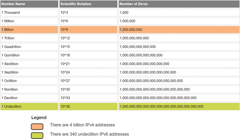
Figure 8-8 IPv4 and IPv6 Address Space
IPv4 Packet Header Fields in the IPv6 Packet Header (8.3.3)
One of the major design improvements of IPv6 over IPv4 is the simplified IPv6 header.
The IPv4 header consists of a variable-length header of 20 octets (up to 60 bytes if the Options field is used) and 12 basic header fields, not including the Options field and the Padding field.
For IPv6, some fields have remained the same, some fields have changed names and positions, and some IPv4 fields are no longer required, as highlighted in Figure 8-9.
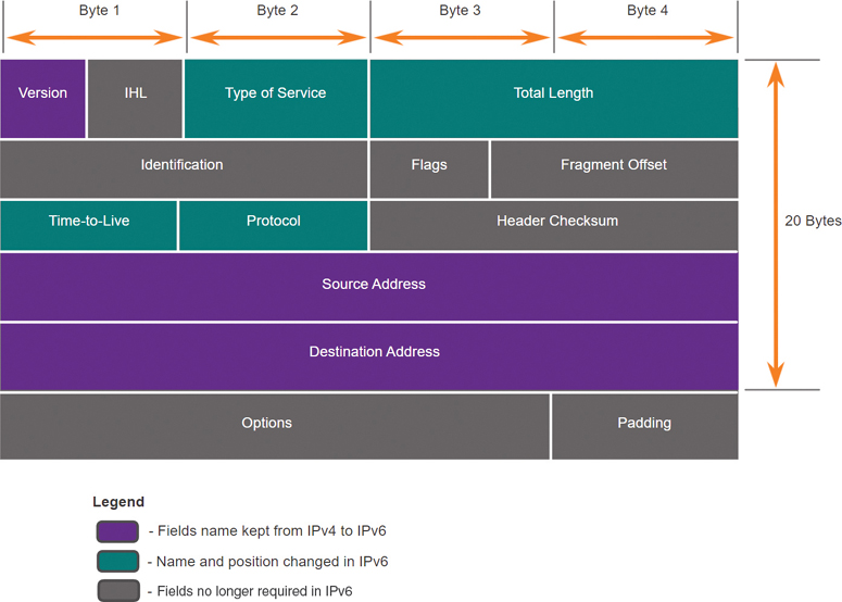
Figure 8-9 IPv4 Fields Kept, Changed, or Removed
The simplified IPv6 header shown in Figure 8-10 consists of a fixed-length header of 40 octets (largely due to the length of the source and destination IPv6 addresses).
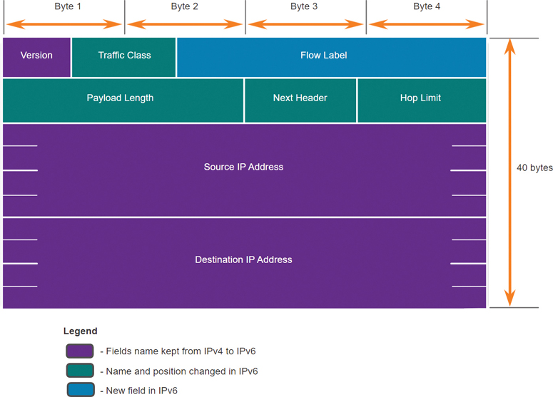
Figure 8-10 IPv6 Packet Header Fields
The simplified IPv6 headers can be processed more efficiently than IPv4 headers.
IPv6 Packet Header (8.3.4)
The fields for the IPv6 packet header, as shown in Figure 8-10, are as follows:
Version: This field contains a 4-bit binary value set to 0110 that identifies this as an IP version 6 packet.
Traffic Class: This 8-bit field is equivalent to the IPv4 Differentiated Services (DS) field.
Flow Label: This 20-bit field suggests that all packets with the same flow label receive the same type of handling by routers.
Payload Length: This 16-bit field indicates the length of the data portion, or payload, of the IPv6 packet. This does not include the length of the IPv6 header, which is a fixed 40-byte header.
Next Header: This 8-bit field is equivalent to the IPv4 Protocol field. It indicates the data payload type that the packet is carrying, enabling the network layer to pass the data to the appropriate upper-layer protocol.
Hop Limit: This 8-bit field replaces the IPv4 TTL field. This value is decremented by 1 each time a router forwards the packet. When the counter reaches 0, the packet is discarded, and an ICMPv6 Time Exceeded message is forwarded to the sending host. This message indicates that the packet did not reach its destination because the hop limit was exceeded. Unlike IPv4, IPv6 does not include an IPv6 Header Checksum field, because this function is performed at both the lower and upper layers. This means the checksum does not need to be recalculated by each router when it decrements the Hop Limit field, which also improves network performance.
Source IPv6 Address: This 128-bit field identifies the IPv6 address of the sending host.
Destination IPv6 Address: This 128-bit field identifies the IPv6 address of the receiving host.
An IPv6 packet may also contain extension headers (EHs), which provide optional network layer information. Extension headers are optional and are placed between the IPv6 header and the payload. EHs are used for fragmentation, security, to support mobility, and more.
Unlike with IPv4, routers do not fragment routed IPv6 packets.
Video—Sample IPv6 Headers in Wireshark (8.3.5)
Refer to the online course to view this video.
Check Your Understanding—IPv6 Packet (8.3.6)
Refer to the online course to complete this activity.
How a Host Routes (8.4)
Hosts need to communicate with hosts that might be on networks other than the local network. This section examines how communication from hosts is able to reach hosts on remote networks.
Host Forwarding Decision (8.4.1)
With both IPv4 and IPv6, packets are always created at the source host. The source host must be able to direct a packet to the destination host. To do this, host end devices create their own routing table. This section discusses how end devices use routing tables.
Another role of the network layer is to direct packets between hosts. A host can send a packet to the following:
Itself: A host can ping itself by sending a packet to the special IPv4 address 127.0.0.1 or the IPv6 address ::/1, which is referred to as the loopback interface. Pinging the loopback interface tests the TCP/IP protocol stack on the host.
Local host: This is a destination host that is on the same local network as the sending host. The source and destination hosts share the same network address.
Remote host: This is a destination host on a remote network. The source and destination hosts do not share the same network address.
Figure 8-11 illustrates PC1 connecting to a local host on the same network and to a remote host located on another network.
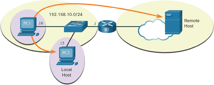
Figure 8-11 Hosts Can Connect to Local and Remote Networks
Whether a packet is destined for a local host or a remote host is determined by the source end device. The source end device determines whether the destination IP address is on the same network that the source device itself is on. The method of determination varies by IP version:
In IPv4: The source device uses its own subnet mask along with its own IPv4 address and the destination IPv4 address to make this determination.
In IPv6: The local router advertises the local network address (prefix) to all devices on the network.
In a home or business network, you may have several wired and wireless devices interconnected together by an intermediary device, such as a LAN switch or a wireless access point (WAP). This intermediary device provides interconnections between local hosts on the local network. Local hosts can reach each other and share information without the need for any additional devices. If a host is sending a packet to a device that is configured with the same IP network as the host device, the packet is simply forwarded out the host interface, through the intermediary device, and to the destination device directly.
Of course, in most situations, we want our devices to be able to connect beyond the local network segment, such as out to other homes, businesses, and the internet. Devices that are beyond the local network segment are known as remote hosts. When a source device sends a packet to a remote destination device, the help of routers and routing is needed. Routing is the process of identifying the best path to a destination. The router connected to the local network segment is referred to as the default gateway.
Default Gateway (8.4.2)
The default gateway is a network device (that is, a router, or Layer 3 switch) that can route traffic to other networks. If you use the analogy of a room for a network, then the default gateway is like a doorway. If you want to get to another room or network, you need to find the doorway.
On a network, a default gateway is usually a router with these features:
It has a local IP address in the same address range as other hosts on the local network.
It can accept data into the local network and forward data out of the local network.
It routes traffic to other networks.
A default gateway is required to send traffic outside the local network. Traffic cannot be forwarded outside the local network if there is no default gateway, the default gateway address is not configured, or the default gateway is down.
A Host Routes to the Default Gateway (8.4.3)
A host routing table typically includes a default gateway. With IPv4, the host receives the IPv4 address of the default gateway either dynamically from Dynamic Host Configuration Protocol (DHCP) or configured manually. With IPv6, the router can advertise the default gateway address or the host can be configured manually.
In Figure 8-12, assume that PC1 and PC2 are configured with the IPv4 address 192.168.10.1 as the default gateway.
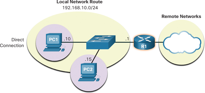
Figure 8-12 Hosts Use a Default Gateway for Remote Network Access
Having a default gateway configured creates a default route in the routing table of the PC. A default route is the route or pathway the computer takes when it tries to contact a remote network.
In Figure 8-12, PC1 and PC2 both have default routes to send all traffic destined to remote networks to R1.
Host Routing Tables (8.4.4)
On a Windows host, the route print or netstat -r command can be used to display the host routing table. Both of these commands generate the same output. The output may seem overwhelming at first, but it is fairly simple to understand.
Figure 8-13 displays a sample topology for host routes.

Figure 8-13 Host Route Topology
Example 8-1 shows the output generated by the netstat -r command on PC1 in Figure 8-13.
Example 8-1 IPv4 Routing Table for PC1
C:\Users\PC1> netstat -r

IPv4 Route Table
===========================================================================
Active Routes:
Network Destination         Netmask        Gateway        Interface    Metric
          0.0.0.0           0.0.0.0   192.168.10.1    192.168.10.10       25
        127.0.0.0          255.0.0.0       On-link        127.0.0.1      306
        127.0.0.1    255.255.255.255       On-link        127.0.0.1      306
  127.255.255.255    255.255.255.255       On-link         127.0.0.1     306
     192.168.10.0      255.255.255.0       On-link     192.168.10.10     281
    192.168.10.10    255.255.255.255       On-link     192.168.10.10     281
   192.168.10.255    255.255.255.255       On-link     192.168.10.10     281
        224.0.0.0          240.0.0.0       On-link         127.0.0.1     306
        224.0.0.0          240.0.0.0       On-link     192.168.10.10     281
  255.255.255.255    255.255.255.255       On-link        127.0.0.1      306
  255.255.255.255    255.255.255.255       On-link     192.168.10.10     281
Note
The output in Example 8-1 displays the IPv4 route table.
The output of the netstat -r command or the equivalent route print command has three sections related to the current TCP/IP network connections:
Interface List: This section lists the Media Access Control (MAC) address and assigned interface number of each network-capable interface on the host, including Ethernet, Wi-Fi, and Bluetooth adapters.
IPv4 Route Table: This section lists all known IPv4 routes, including direct connections, the local network, and local default routes.
IPv6 Route Table: This section lists all known IPv6 routes, including direct connections, the local network, and local default routes.
Check Your Understanding—How a Host Routes (8.4.5)
Refer to the online course to complete this activity.
Introduction to Routing (8.5)
This section introduces the role of the router in the routing process and provides an introduction the use of routing tables for forwarding packets.
Router Packet Forwarding Decision (8.5.1)
In this chapter, you have already learned about host routing tables. Most networks also contain routers, which are intermediary devices that also contain routing tables. This section covers router operations at the network layer. When a host sends a packet to another host, it consults its routing table to determine where to send the packet. If the destination host is on a remote network, the packet is forwarded to the default gateway, which is usually the local router.
What happens when a packet arrives on a router interface? The router examines the destination IP address of the packet and searches its routing table to determine where to forward the packet. The routing table contains a list of all known network addresses (prefixes) and where to forward the packet. These entries are known as route entries or routes. The router forwards a packet using the route entry that matches best (that is, is longest). Figure 8-14 illustrates this forwarding process:
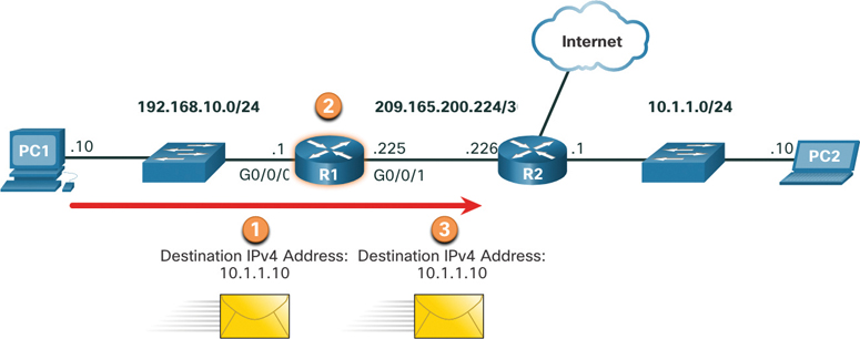
Figure 8-14 Packet Forwarding Process
Step 1. The packet arrives on the Gigabit Ethernet 0/0/0 interface of router R1. R1 de-encapsulates the Layer 2 Ethernet header and trailer.
Step 2. Router R1 examines the destination IPv4 address of the packet and searches for the best match in its IPv4 routing table. The route entry indicates that this packet is to be forwarded to router R2.
Step 3. Router R1 encapsulates the packet into a new Ethernet header and trailer and forwards the packet to the next hop router R2.
Table 8-1 shows the pertinent information from the R1 routing table.
Table 8-1 R1 Routing Table
Route |
Next Hop or Exit Interface |
192.168.10.0/24 |
G0/0/0 |
209.165.200.224/30 |
G0/0/1 |
10.1.1.0/24 |
Through R2 |
Default Route 0.0.0.0/0 |
Through R2 |
IP Router Routing Table (8.5.2)
The routing table of a router contains network route entries that list all the possible known network destinations.
The routing table stores three types of route entries:
Directly connected networks: These network route entries are active router interfaces. A router adds a directly connected route when an interface is configured with an IP address and is activated. Each router interface is connected to a different network segment. In Figure 8-15, the directly connected networks in the R1 IPv4 routing table would be 192.168.10.0/24 and 209.165.200.224/30.
Remote networks: These network route entries are connected to other routers. Routers learn about remote networks either by being explicitly configured by an administrator or by exchanging route information using a dynamic routing protocol. In Figure 8-15, the remote network in the R1 IPv4 routing table would be 10.1.1.0/24.
Default route: Like a host, most routers also include a default route entry, a gateway of last resort. The default route is used when there is no better (longer) match in the IP routing table. In Figure 8-15, the R1 IPv4 routing table would most likely include a default route to forward all packets to router R2.

Figure 8-15 Example Topology of Directly Connected and Remote Networks
Figure 8-15 identifies the directly connected and remote networks of router R1.
In Figure 8-15, R1 has two directly connect networks:
192.168.10.0/24
209.165.200.224/30
R1 also has remote networks (that is, 10.1.1.0/24 and the internet) that it can learn about.
A router can learn about remote networks in one of two ways:
Manually: Remote networks are manually entered into the route table using static routes.
Dynamically: Remote routes are automatically learned using a dynamic routing protocol.
Static Routing (8.5.3)
Static routes are route entries that are manually configured. Figure 8-16 shows an example of a static route that was manually configured on router R1. A static route includes the remote network address and the IP address of the next hop router.
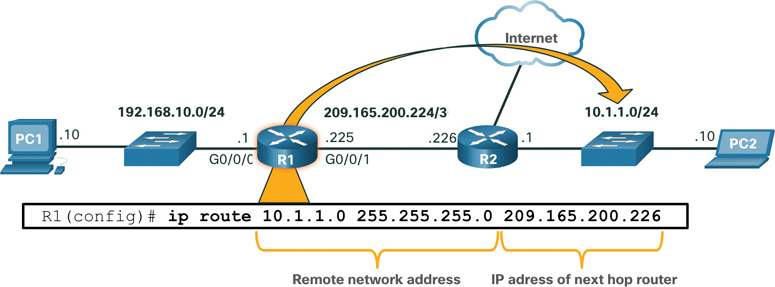
Figure 8-16 Static Routing Example
If there is a change in the network topology, a static route is not automatically updated and must be manually reconfigured. For example, in Figure 8-17, R1 has a static route to reach the 10.1.1.0/24 network via R2. If that path becomes unavailable, R1 needs to be reconfigured with a new static route to the 10.1.1.0/24 network via R3. Router R3 therefore needs to have a route entry in its routing table to send packets destined for 10.1.1.0/24 to R2.
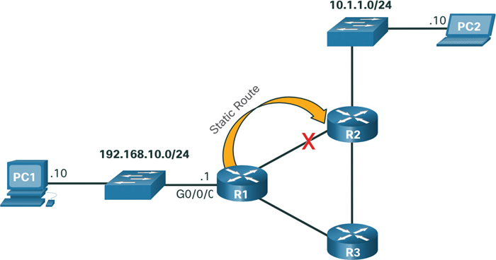
Figure 8-17 Static Routing Does Not Automatically Update to Topology Changes
Static routing has the following characteristics:
A static route must be configured manually.
The administrator needs to reconfigure a static route if there is a change in the topology and the static route is no longer viable.
A static route is appropriate for a small network and when there are few or no redundant links.
A static route is commonly used with a dynamic routing protocol for configuring a default route.
Dynamic Routing (8.5.4)
A dynamic routing protocol allows the routers to automatically learn about remote networks, including a default route, from other routers. Routers that use dynamic routing protocols automatically share routing information with other routers and compensate for any topology changes without involving the network administrator. If there is a change in the network topology, routers share this information using the dynamic routing protocol and automatically update their routing tables.
Dynamic routing protocols include OSPF and Enhanced Interior Gateway Routing Protocol (EIGRP). Figure 8-18 shows an example of routers R1 and R2 automatically sharing network information using the routing protocol OSPF.
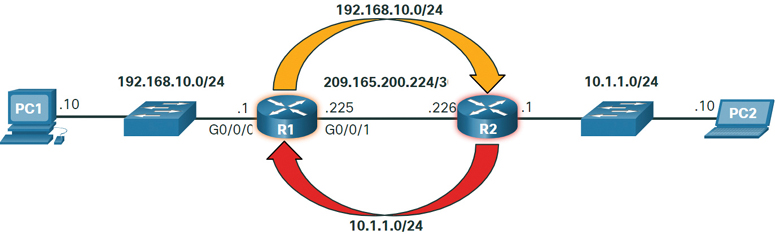
Figure 8-18 Dynamic Routing Example
Basic dynamic routing configuration only requires the network administrator to enable the directly connected networks within the dynamic routing protocol. The dynamic routing protocol automatically does the following:
Discovers remote networks
Maintains up-to-date routing information
Chooses the best paths to destination networks
Attempts to find a new best path if the current path is no longer available
When a router is manually configured with a static route or learns about a remote network dynamically using a dynamic routing protocol, the remote network address and next hop address are entered into the IP routing table. As shown Figure 8-19, if there is a change in the network topology, the routers automatically adjust and attempt to find a new best path.
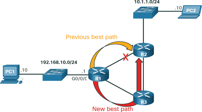
Figure 8-19 Dynamic Routing Automatically Updates to Topology Changes
Note
It is common for some routers to use a combination of both static routes and a dynamic routing protocol.
Video—IPv4 Router Routing Tables (8.5.5)
Refer to the online course to view this video.
Introduction to an IPv4 Routing Table (8.5.6)
Notice in Figure 8-20 that R2 is connected to the internet. Therefore, the administrator configured R1 with a default static route sending packets to R2 when there is no specific entry in the routing table that matches the destination IP address. R1 and R2 are also using OSPF routing to advertise directly connected networks.
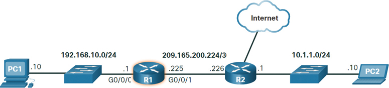
Figure 8-20 Sample Topology for IPv4 Routing Table
The show ip route privileged EXEC mode command is used to view the IPv4 routing table on a Cisco IOS router. Example 8-2 shows the IPv4 routing table of router R1.
Example 8-2 R1 IPv4 Routing Table
R1# show ip route
Codes: L - local, C - connected, S - static, R - RIP, M - mobile, B - BGP
       D - EIGRP, EX - EIGRP external, O - OSPF, IA - OSPF inter area
       N1 - OSPF NSSA external type 1, N2 - OSPF NSSA external type 2
       E1 - OSPF external type 1, E2 - OSPF external type 2
       i - IS-IS, su - IS-IS summary, L1 - IS-IS level-1, L2 - IS-IS level-2
       ia - IS-IS inter area, * - candidate default, U - per-user static route
       o - ODR, P - periodic downloaded static route, H - NHRP, l - LISP
       a - application route
       + - replicated route, % - next hop override, p - overrides from PfR
Gateway of last resort is 209.165.200.226 to network 0.0.0.0
S*    0.0.0.0/0 [1/0] via 209.165.200.226, GigabitEthernet0/0/1
      10.0.0.0/24 is subnetted, 1 subnets
O        10.1.1.0 [110/2] via 209.165.200.226, 00:02:45, GigabitEthernet0/0/1
      192.168.10.0/24 is variably subnetted, 2 subnets, 2 masks
C        192.168.10.0/24 is directly connected, GigabitEthernet0/0/0
L        192.168.10.1/32 is directly connected, GigabitEthernet0/0/0
      209.165.200.0/24 is variably subnetted, 2 subnets, 2 masks
C        209.165.200.224/30 is directly connected, GigabitEthernet0/0/1
L        209.165.200.225/32 is directly connected, GigabitEthernet0/0/1
R1#
At the beginning of each routing table entry is a code that is used to identify the type of route or how the route was learned. Common route sources (codes) include these:
L: Directly connected local interface IP address
C: Directly connected network
S: Static route manually configured by an administrator
O: OSPF
D: EIGRP
The routing table displays all of the known IPv4 destination routes for R1.
A directly connected route is automatically created when a router interface is configured with IP address information and is activated. The router adds two route entries with the codes C (that is, the connected network) and L (that is, the local interface IP address of the connected network). The route entries also identify the exit interface to use to reach the network. The two directly connected networks in this example are 192.168.10.0/24 and 209.165.200.224/30.
Routers R1 and R2 are also using the OSPF dynamic routing protocol to exchange router information. In the sample routing table, R1 has a route entry for the 10.1.1.0/24 network that it learned dynamically from router R2 thanks to the OSPF routing protocol.
A default route has a network address of all zeros. For example, say that the IPv4 network address is 0.0.0.0. A static route entry in the routing table begins with the code S*, as highlighted in Example 8-2.
Check Your Understanding—Introduction to Routing (8.5.7)
Refer to the online course to complete this activity.
Summary (8.6)
The following is a summary of the topics in the chapter and their corresponding online modules.
Network Layer Characteristics
The network layer (OSI Layer 3) provides services to allow end devices to exchange data across networks. IPv4 and IPv6 are the principal network layer communication protocols. The network layer also includes the routing protocol OSPF and messaging protocols such as ICMP. Network layer protocols perform four basic operations: addressing end devices, encapsulation, routing, and de-encapsulation. IPv4 and IPv6 specify the packet structure and processing used to carry the data from one host to another host. IP encapsulates the transport layer segment by adding an IP header, which is used to deliver the packet to the destination host. The IP header is examined by Layer 3 devices (that is, routers) as it travels across a network to its destination. IP is connectionless, meaning that it creates no dedicated end-to-end connection before data is sent. In addition, IP is best effort, meaning that it does not guarantee that all packets that are sent are, in fact, received. Finally, IP is media independent, meaning that it operates independently of the media that carry the data at lower layers of the protocol stack.
IPv4 Packet
An IPv4 packet header consists of fields containing information about the packet. These fields contain binary numbers that are examined by the Layer 3 process. The binary values of the fields identify various settings of the IP packet. Significant fields in the IPv4 header include Version, DS, Header Checksum, TTL, Protocol, Source IPv4 Address, and Destination IPv4 Address.
IPv6 Packet
IPv6 is designed to overcome the limitations of IPv4, including IPv4 address depletion, lack of end-to-end connectivity, and increased network complexity. IPv6 increases the available address space, improves packet handling, and eliminates the need for NAT. The fields in the IPv6 packet header include Version, Traffic Class, Flow Label, Payload Length, Next Header, Hop Limit, Source IPv6 Address, and Destination IPv6 Address.
How a Host Routes
A host can send a packet to itself, to another local host, or to a remote host. In IPv4, the source device uses its own subnet mask along with its own IPv4 address and the destination IPv4 address to determine whether the destination host is on the same network. In IPv6, the local router advertises the local network address (prefix) to all devices on the network to make this determination. The default gateway is the network device (that is, router) that can route traffic to other networks. On a network, a default gateway is usually a router that has a local IP address in the same address range as other hosts on the local network, can accept data into the local network and forward data out the local network, and can route traffic to other networks. A host routing table typically includes a default gateway. In IPv4, the host may receive the IPv4 address of the default gateway dynamically through DHCP, or it may be configured manually. In IPv6, the router can advertise the default gateway address, or the host can be configured manually. On a Windows host, the route print or netstat -r command can be used to display the host routing table.
Introduction to Routing
When a host sends a packet to another host, it consults its routing table to determine where to send the packet. If the destination host is on a remote network, the packet is forwarded to the default gateway, which is usually the local router. What happens when a packet arrives on a router interface? The router examines the packet’s destination IP address and searches its routing table to determine where to forward the packet. The routing table contains a list of all known network addresses (prefixes) and where to forward the packet. These entries are known as route entries, or routes. The router forwards the packet using the best (longest) matching route entry. The routing table of a router stores three types of route entries: directly connected networks, remote networks, and a default route. Routers learn about remote networks either manually or dynamically using a dynamic routing protocol. Static routes are route entries that are manually configured. A static route includes the remote network address and the IP address of the next hop router. OSPF and EIGRP are two dynamic routing protocols. The show ip route privileged EXEC mode command is used to view the IPv4 routing table on a Cisco IOS router. At the beginning of an IPv4 routing table is a code that is used to identify the type of route or how the route was learned. Common route sources (codes) include:
L: Directly connected local interface IP address
C: Directly connected network
S: Static route manually configured by an administrator
O: Open Shortest Path First (OSPF)
D: Enhanced Interior Gateway Routing Protocol (EIGRP)
Practice
There are no labs or Packet Tracer activities for this chapter.
Check Your Understanding Questions
Complete all the review questions listed here to test your understanding of the topics and concepts in this chapter. The appendix “Answers to ‘Check Your Understanding’ Questions” lists the answers.
1. Which information is used by routers to forward a data packet toward its destination?
source IP address
destination IP address
source data link address
destination data link address
2. A computer has to send a packet to a destination host in the same LAN. How will the packet be sent?
The packet will be sent to the default gateway first, and then, depending on the response from the gateway, it may be sent to the destination host.
The packet will be sent directly to the destination host.
The packet will first be sent to the default gateway, and then from the default gateway it will be sent directly to the destination host.
The packet will be sent only to the default gateway.
3. A router receives a packet from the Gigabit Ethernet 0/0/0 interface and determines that the packet needs to be forwarded out the Gigabit Ethernet 0/0/1 interface. What will the router do next?
route the packet out the Gigabit Ethernet 0/0/1 interface
create a new Layer 2 Ethernet frame to be sent to the destination
look into the ARP cache to determine the destination IP address
look into the routing table to determine if the destination network is in the routing table
4. Which IPv4 address can a host use to ping the loopback interface?
126.0.0.1
127.0.0.0
126.0.0.0
127.0.0.1
5. When a connectionless protocol is in use at a lower layer of the OSI model, how is missing data detected and retransmitted if necessary?
Connectionless acknowledgments are used to request retransmission.
An upper-layer connection-oriented protocol keeps track of the data received and can request retransmission from the upper-level protocol on the sending host.
Network layer IP protocols manage the communication sessions if connection-oriented transport services are not available.
The best-effort delivery process guarantees that all packets that are sent are received.
6. What was the main reason for the creation and implementation of IPv6?
to make reading a 32-bit address easier
to address the IPv4 address depletion problem
to provide more address space in the Internet Names Registry
to allow NAT support for private addressing
7. Which statement accurately describes a characteristic of IPv4?
All IPv4 addresses are assignable to hosts.
IPv4 has a 32-bit address space.
An IPv4 header has fewer fields than an IPv6 header has.
IPv4 has a 128-bit address space.
8. When a router receives an IPv6 packet, what information is examined in order to see if the packet has exceeded the number of routers that can forward the packet?
destination IP address
source IP address
hop limit
TTL
9. Which field in an IPv6 packet does a router use to determine whether the packet has expired and should be dropped?
TTL
Hop Limit
Address Unreachable
No Route to Destination
10. Which command can be used on a Windows host to display the routing table?
netstat -s
show ip route
netstat -r
print route
11. What information is added during encapsulation at OSI Layer 3?
source and destination MAC addresses
source and destination application protocols
source and destination port numbers
source and destination IP addresses
12. How does the network layer determine the MTU value?
The network layer depends on the higher-level layers to determine the MTU.
The network layer depends on the data link layer to set the MTU and adjusts the speed of transmission to accommodate it.
The network layer determines how large packets can be, based on the MTU of the data link frame.
To increase speed delivery, the network layer ignores the MTU.
13. Which characteristic describes an IPv6 enhancement over IPv4?
IPv6 is based on 128-bit flat addressing, whereas IPv4 is based on 32-bit hierarchical addressing.
The IPv6 header is simpler than the IPv4 header, which improves packet handling.
Both IPv4 and IPv6 support authentication, but only IPv6 supports privacy capabilities.
The IPv6 address space is four times bigger than the IPv4 address space.