Chapter 11
IPv4 Addressing
Objectives
Upon completion of this chapter, you will be able to answer the following questions:
What is the structure of an IPv4 address, including the network portion, the host portion, and the subnet mask?
What are the characteristics and uses of unicast, broadcast, and multicast IPv4 addresses?
What are public, private, and reserved IPv4 addresses?
How does subnetting a network enable better communication?
How do you calculate IPv4 subnets for a /24 prefix?
How do you calculate IPv4 subnets for /16 and /8 prefixes?
Given a set of requirements for subnetting, how do you implement an IPv4 addressing scheme?
How do you create a flexible addressing scheme using variable-length subnet masking (VLSM)?
How do you implement a VLSM addressing scheme?
Key Terms
This chapter uses the following key terms. You can find the definitions in the glossary at the end of the book.
Introduction (11.0)
Plenty of networks are still using IPv4 addressing today, while organizations are making the transition to IPv6. So it is still very important for network administrators to know everything they can about IPv4 addressing. This chapter covers the fundamental aspects of IPv4 addressing in detail. It covers how to segment a network into subnets and how to use variable-length subnet masking (VLSM) as part of an overall IPv4 addressing scheme. Subnetting is like cutting a pie into smaller and smaller pieces. Subnetting may seem overwhelming at first, but we show you some tricks to help you along the way. This chapter includes several videos, activities to help you practice subnetting, Packet Tracer activities, and labs. Once you get the hang of Pv4 addressing, you’ll be on your way to network administration!
IPv4 Address Structure (11.1)
This section presents the IPv4 address structure.
Network and Host Portions (11.1.1)
An IPv4 address is a 32-bit hierarchical address that is made up of a network portion and a host portion. When determining the network portion versus the host portion, you must look at the 32-bit stream, as shown in Figure 11-1.
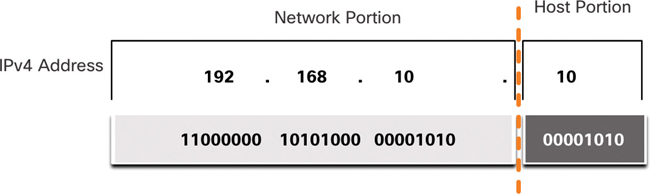
Figure 11-1 Network and Host Portions of an IPv4 Address
The bits in the network portion of the address must be identical for all devices that reside in the same network. The bits in the host portion of the address must be unique to identify a specific host within a network. If two hosts have the same bit pattern in the specified network portion of the 32-bit stream, those two hosts reside in the same network.
But how do hosts know which portion of the 32 bits identifies the network and which identifies the host? That is the role of the subnet mask.
The Subnet Mask (11.1.2)
As shown in Figure 11-2, assigning an IPv4 address to a host requires the following:
IPv4 address: This is the unique IPv4 address of the host.
Subnet mask: This is used to identify the network/host portion of the IPv4 address.

Figure 11-2 IPv4 Addressing on a Windows PC
Note
A default gateway IPv4 address is required to reach remote networks, and DNS server IPv4 addresses are required to translate domain names to IPv4 addresses.
The IPv4 subnet mask is used to differentiate the network portion from the host portion of an IPv4 address. When an IPv4 address is assigned to a device, the subnet mask is used to determine the network address of the device. The network address represents all the devices on the same network.
Figure 11-3 displays the 32-bit subnet mask in dotted decimal and binary formats.
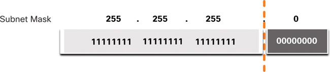
Figure 11-3 32-Bit Subnet Mask
Notice that the subnet mask is a consecutive sequence of 1 bits followed by a consecutive sequence of 0 bits.
To identify the network and host portions of an IPv4 address, the subnet mask is compared to the IPv4 address bit for bit, from left to right, as shown in Figure 11-4.
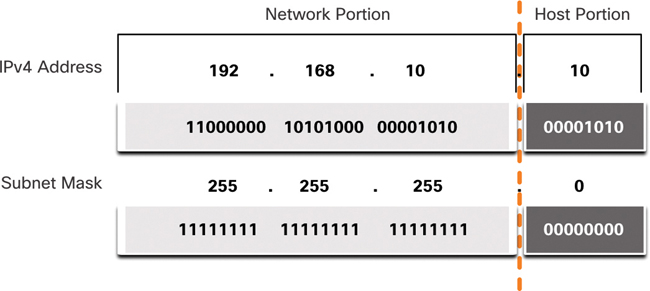
Figure 11-4 Subnet Mask Compared to IPv4 Address
Note that the subnet mask does not actually contain the network or host portion of an IPv4 address; it just tells the computer where to look for the part of the IPv4 address that is the network portion and where to look for the host portion. The process used to identify the network portion and host portion is called ANDing.
The Prefix Length (11.1.3)
Expressing network addresses and host addresses by using dotted decimal subnet mask addresses can be cumbersome. Fortunately, there is an alternative method of identifying a subnet mask: a method called the prefix length.
The prefix length is the number of bits set to 1 in the subnet mask. It is written in “slash notation,” with a forward slash (/) followed by the number of bits set to 1. To figure out the prefix length, count the number of bits in the subnet mask and prepend it with a slash. Table 11-1 provides some examples. The first column lists various subnet masks that can be used with a host address. The second column displays the converted 32-bit binary address. The last column displays the resulting prefix length.
Table 11-1 Comparing the Subnet Mask and Prefix Length
Subnet Mask |
32-Bit Address |
Prefix Length |
255.0.0.0 |
11111111.00000000.00000000.00000000 |
/8 |
255.255.0.0 |
11111111.11111111.00000000.00000000 |
/16 |
255.255.255.0 |
11111111.11111111.11111111.00000000 |
/24 |
255.255.255.128 |
11111111.11111111.11111111.10000000 |
/25 |
255.255.255.192 |
11111111.11111111.11111111.11000000 |
/26 |
255.255.255.224 |
11111111.11111111.11111111.11100000 |
/27 |
255.255.255.240 |
11111111.11111111.11111111.11110000 |
/28 |
255.255.255.248 |
11111111.11111111.11111111.11111000 |
/29 |
255.255.255.252 |
11111111.11111111.11111111.11111100 |
/30 |
Note
A network address is also referred to as a prefix or network prefix. Therefore, the prefix length is the number of 1 bits in the subnet mask.
When representing an IPv4 address using a prefix length, the IPv4 address is written followed by the prefix length with no spaces. For example, 192.168.10.10 255.255.255.0 would be written as 192.168.10.10/24. Later in this chapter, you’ll learn more about using various types of prefix lengths. For now, we focus on the /24 (that is, 255.255.255.0) prefix.
Determining the Network: Logical AND (11.1.4)
A logical AND is one of three Boolean operations used in Boolean or digital logic. The other two are OR and NOT. The AND operation is used in determining the network address.
Logical AND compares two bits and produces a result, as shown here:
1 AND 1 = 1
0 AND 1 = 0
1 AND 0 = 0
0 AND 0 = 0
Note that only a 1 AND 1 produces 1. Any other combination results in 0.
Note
In digital logic, 1 represents true, and 0 represents false. When using an AND operation, both input values must be true (1) for the result to be true (1).
To identify the network address of an IPv4 host, the IPv4 address is logically ANDed, bit by bit, with the subnet mask. ANDing between the address and the subnet mask yields the network address.
To illustrate how AND is used to discover a network address, consider a host with IPv4 address 192.168.10.10 and subnet mask 255.255.255.0, as shown in Figure 11-5:
IPv4 host address (192.168.10.10): Display the IPv4 address of the host in dotted decimal and binary formats.
Subnet mask (255.255.255.0): Display the subnet mask of the host in dotted decimal and binary formats.
Network address (192.168.10.0): The logical AND operation between the IPv4 address and subnet mask results in an IPv4 network address shown in dotted decimal and binary formats.

Figure 11-5 ANDing Example
Using the first sequence of bits as an example, notice that the AND operation is performed on the 1 bit of the host address with the 1 bit of the subnet mask. This results in a 1 bit for the network address: 1 AND 1 = 1.
The AND operation between an IPv4 host address and subnet mask results in the IPv4 network address for this host. In this example, the AND operation between the host address 192.168.10.10 and the subnet mask 255.255.255.0 (/24), results in the IPv4 network address 192.168.10.0/24. This is an important IPv4 operation, as it tells the host what network it belongs to.
Video—Network, Host, and Broadcast Addresses (11.1.5)

Refer to the online course to view this video.
Network, Host, and Broadcast Addresses (11.1.6)
Within each network are three types of IP addresses:
Network address
Host addresses
Broadcast address
The following sections examine these three types of addresses, using the topology in Figure 11-6.

Figure 11-6 Network Address and Host Addresses Example
Network Address
A network address is an address that represents a specific network. A device belongs to this network if it meets three criteria:
It has the same subnet mask as the network address.
It has the same network bits as the network address, as indicated by the subnet mask.
It is located in the same broadcast domain as other hosts with the same network address.
A host determines its network address by performing an AND operation between its IPv4 address and its subnet mask.
As shown in Table 11-2, the network address has all 0 bits in the host portion, as determined by the subnet mask. In this example, the network address is 192.168.10.0/24. A network address cannot be assigned to a device.
Table 11-2 Network, Host, and Broadcast Addresses
|
Network Portion |
Host Portion |
Host Bits |
Subnet mask: 255.255.255.0 or /24 |
255 255 255 11111111 11111111 11111111 |
0 00000000 |
|
Network address: 192.168.10.0 or /24 |
192 168 10 11000000 10100000 00001010 |
0 00000000 |
All 0s |
First address: 192.168.10.1 or /24 |
192 168 10 11000000 10100000 00001010 |
1 00000001 |
All 0s and a 1 |
Last address: 192.168.10.254 or /24 |
192 168 10 11000000 10100000 00001010 |
254 11111110 |
All 1s and a 0 |
Broadcast address: 192.168.10.255 or /24 |
192 168 10 11000000 10100000 00001010 |
255 11111111 |
All 1s |
Host Addresses
Host addresses are addresses that can be assigned to devices such as host computers, laptops, smartphones, web cameras, printers, routers, and so on. The host portion of the address is the bits indicated by 0 bits in the subnet mask. A host address can have any combination of bits in the host portion except for all 0 bits (which would be a network address) or all 1 bits (which would be a broadcast address).
All devices in the same network must have the same subnet mask and the same network bits. Only the host bits differ and must be unique.
In Table 11-2, notice that there is a first host address, and there is a last host address:
First host address: The first host in a network has all 0 bits, with the last (rightmost) bit as a 1 bit. In this example, it is 192.168.10.1/24.
Last host address: The last host in a network has all 1 bits, with the last (rightmost) bit as a 0 bit. In this example, it is 192.168.10.254/24.
Any addresses between and including the first and last host addresses—in this case, 192.168.10.1/24 through 192.168.10.254/24—can be assigned to devices on the network.
Broadcast Address
A broadcast address is an address that is used to reach all devices on the IPv4 network. As shown in Table 11-2, the network broadcast address has all 1 bits in the host portion, as determined by the subnet mask. In this example, the network address is 192.168.10.255/24. A broadcast address cannot be assigned to a device.
Activity—ANDing to Determine the Network Address (11.1.7)

Use the ANDing process to determine the network address (in binary and decimal formats).
Refer to the online course to complete this activity.
Check Your Understanding—IPv4 Address Structure (11.1.8)
Refer to the online course to complete this activity.
IPv4 Unicast, Broadcast, and Multicast (11.2)
In IPv4 data networks, communication can take place as unicast, broadcast, or multicast. This section discusses these three methods of communication in IPv4.
Unicast (11.2.1)
In the previous section, you learned about the structure of an IPv4 address; each has a network portion and a host portion. There are different ways to send a packet from a source device, and these different transmissions affect the destination IPv4 addresses.
Unicast transmission refers to one device sending a message to one other device in one-to-one communications.
A unicast packet has a destination IP address that is a unicast address, which goes to a single recipient. A source IP address can only be a unicast address because the packet can only originate from a single source—regardless of whether the destination IP address is a unicast, broadcast, or multicast address.
Figure 11-7 shows an example of unicast transmission.

Figure 11-7 Unicast Transmission
Note
In this book, all communication between devices is unicast unless otherwise noted.
IPv4 unicast host addresses are in the address range 1.1.1.1 to 223.255.255.255. However, within this range are many addresses that are reserved for special purposes. These special-purpose addresses are discussed later in this chapter.
Broadcast (11.2.2)
Broadcast transmission refers to a device sending a message to all the devices on a network in one-to-all communications.
A broadcast packet has a destination IP address with all 1s in the host portion, or 32 1 bits.
Note
IPv4 uses broadcast packets. However, there are no broadcast packets with IPv6.
A broadcast packet must be processed by all devices in the same broadcast domain. A broadcast domain identifies all hosts on the same network segment. A broadcast may be directed or limited. A directed broadcast is sent to all hosts on a specific network. For example, say that a host on the 172.16.4.0/24 network sends a packet to 172.16.4.255. A limited broadcast is sent to 255.255.255.255. By default, routers do not forward broadcasts.
Figure 11-8 shows an example of a limited broadcast transmission.
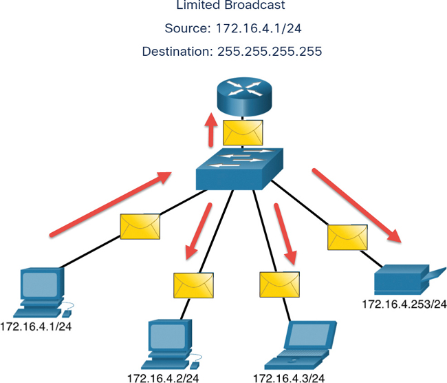
Figure 11-8 Broadcast Transmission
Broadcast packets use resources on the network and make every receiving host on the network process the packet. Therefore, broadcast traffic should be limited so that it does not adversely affect the performance of the network or devices. Because routers separate broadcast domains, subdividing networks can improve network performance by eliminating excessive broadcast traffic.
IP Directed Broadcasts
In addition to the 255.255.255.255 broadcast address, there is a broadcast IPv4 address for each network. This address, called a directed broadcast, uses the highest address in the network, which is the address where all the host bits are 1s. For example, the directed broadcast address for 192.168.1.0/24 is 192.168.1.255. This address allows communication to all the hosts in that network. To send data to all the hosts in a network, a host can send a single packet that is addressed to the broadcast address of the network.
A device that is not directly connected to the destination network forwards an IP directed broadcast in the same way it would forward unicast IP packets destined to a host on that network. When a directed broadcast packet reaches a router that is directly connected to the destination network, that packet is broadcast on the destination network.
Note
Because of security concerns and prior abuse from malicious users, directed broadcasts are turned off by default starting with Cisco IOS Release 12.0 with the global configuration command no ip directed-broadcasts.
Multicast (11.2.3)
Multicast transmission reduces traffic by allowing a host to send a single packet to a selected set of hosts that subscribe to a multicast group.
A multicast packet is a packet with a destination IP address that is a multicast address. IPv4 has reserved the 224.0.0.0 to 239.255.255.255 addresses as a multicast range.
Hosts that receive particular multicast packets are called multicast clients. The multicast clients use services requested by a client program to subscribe to the multicast group.
Each multicast group is represented by a single IPv4 multicast destination address. When an IPv4 host subscribes to a multicast group, the host processes packets addressed to this multicast address and packets addressed to its uniquely allocated unicast address.
Routing protocols such as OSPF use multicast transmissions. For example, routers enabled with OSPF communicate with each other using the reserved OSPF multicast address 224.0.0.5. Only devices enabled with OSPF process these packets with 224.0.0.5 as the destination IPv4 address. All other devices ignore these packets.
Figure 11-9 illustrates clients accepting multicast packets.
Activity—Unicast, Broadcast, or Multicast (11.2.4)
Refer to the online course to complete this activity.

Figure 11-9 Multicast Transmission
Types of IPv4 Addresses (11.3)
This section discusses the different types of IPv4 addresses, including public, private, and legacy classful addresses.
Public and Private IPv4 Addresses (11.3.1)
Just as there are different ways to transmit an IPv4 packet, there are also different types of IPv4 addresses. Some IPv4 addresses cannot be used to go out to the internet, and others are specifically allocated for routing to the internet. Some are used to verify a connection, and others are self-assigned. As a network administrator, you will eventually become very familiar with the types of IPv4 addresses, but for now, you should at least know what they are and when to use them.
Public IPv4 addresses are addresses that are globally routed between internet service provider (ISP) routers. However, not all available IPv4 addresses can be used on the internet. There are blocks of addresses called private addresses that are used by most organizations to assign IPv4 addresses to internal hosts.
In the mid-1990s, with the introduction of the World Wide Web (WWW), the private IPv4 addresses in Table 11-3 were introduced to deal with the depletion of IPv4 address space. Private IPv4 addresses are not unique and can be used internally within any network.
Note
The long-term solution to IPv4 address depletion is IPv6.
Table 11-3 The Private Address Blocks
Network Address and Prefix |
RFC 1918 Private Address Range |
10.0.0.0/8 |
10.0.0.0–10.255.255.255 |
172.16.0.0/12 |
172.16.0.0–172.31.255.255 |
192.168.0.0/16 |
192.168.0.0–192.168.255.255 |
Note
Private addresses are defined in RFC 1918 and sometimes referred to as RFC 1918 address space.
Routing to the Internet (11.3.2)
Most internal networks, from large enterprises to home networks, use private IPv4 addresses for addressing all internal devices (in intranets), including hosts and routers. However, private addresses are not globally routable.
In Figure 11-10, customer networks 1, 2, and 3 are sending packets outside their internal networks. These packets have a source IPv4 address that is a private address and a destination IPv4 address that is public (globally routable). Packets with private addresses must be filtered (discarded) or have their addresses translated to public addresses before being forwarded to an ISP.
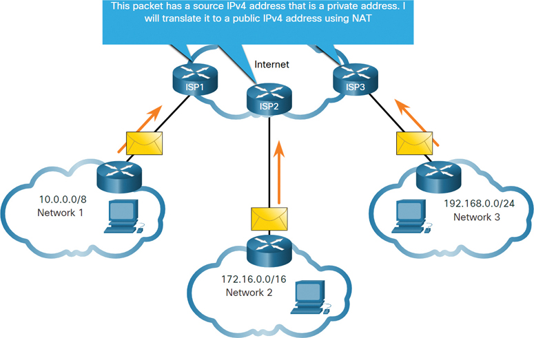
Figure 11-10 Private IPv4 Addresses Translated to Public IPv4 Addresses
Before the ISP can forward this packet, it must translate the source IPv4 address, which is a private address, to a public IPv4 address using Network Address Translation (NAT). NAT is used to translate between private IPv4 and public IPv4 addresses. This is usually done on the router that connects the internal network to the ISP network. Private IPv4 addresses in the organization’s intranet are translated to public IPv4 addresses before routing to the internet.
Note
Although a device with a private IPv4 address is not directly accessible from another device across the internet, the IETF does not consider private IPv4 addresses and NAT to be effective security measures.
Organizations that have resources available to the internet, such as a web server, also have devices that have public IPv4 addresses. As shown in Figure 11-11, this part of the network is known as the DMZ (demilitarized zone). The router in the figure not only performs routing, it also performs NAT and acts as a firewall for security.

Figure 11-11 Example of a DMZ with Public IPv4 Addressing
Note
Private IPv4 addresses are commonly used for educational purposes to ensure that the addresses used are not public IPv4 addresses that belong to organizations.
Activity—Pass or Block IPv4 Addresses (11.3.3)
Refer to the online course to complete this activity.
Special Use IPv4 Addresses (11.3.4)
Certain addresses, such as the network address and broadcast address, cannot be assigned to hosts. In addition, special addresses can be assigned to hosts but with restrictions on how those hosts can interact within the network.
Loopback Addresses
A loopback address (in the range 127.0.0.0/8 or 127.0.0.1 to 127.255.255.254, though more commonly identified as only 127.0.0.1) is a special address that a host uses to direct traffic to itself. For example, the loopback address can be used on a host to test whether the TCP/IP configuration is operational, as shown in Example 11-1. Notice how the 127.0.0.1 loopback address replies to the ping command. Also notice that any address within this block will loop back to the local host, which is shown with the second ping.
Example 11-1 Pinging the Loopback Interface
C:\Users\NetAcad> ping 127.0.0.1
Pinging 127.0.0.1 with 32 bytes of data:
Reply from 127.0.0.1: bytes=32 time<1ms TTL=128
Reply from 127.0.0.1: bytes=32 time<1ms TTL=128
Reply from 127.0.0.1: bytes=32 time<1ms TTL=128
Reply from 127.0.0.1: bytes=32 time<1ms TTL=128
Ping statistics for 127.0.0.1:
    Packets: Sent = 4, Received = 4, Lost = 0 (0% loss),
Approximate round trip times in milli-seconds:
    Minimum = 0ms, Maximum = 0ms, Average = 0ms
C:\Users\NetAcad> ping 127.1.1.1
Pinging 127.1.1.1 with 32 bytes of data:
Reply from 127.1.1.1: bytes=32 time<1ms TTL=128
Reply from 127.1.1.1: bytes=32 time<1ms TTL=128
Reply from 127.1.1.1: bytes=32 time<1ms TTL=128
Reply from 127.1.1.1: bytes=32 time<1ms TTL=128
Ping statistics for 127.1.1.1:
    Packets: Sent = 4, Received = 4, Lost = 0 (0% loss),
Approximate round trip times in milli-seconds:
    Minimum = 0ms, Maximum = 0ms, Average = 0ms
C:\Users\NetAcad>
Link-Local Addresses
Link-local addresses (in the range 169.254.0.0/16 or 169.254.0.1 to 169.254.255.254) are more commonly known as the Automatic Private IP Addressing (APIPA) addresses, or self-assigned addresses. They are used by a Windows DHCP client to self-configure in the event that there are no DHCP servers available. Link-local addresses can be used in a peer-to-peer connection but are not commonly used for this purpose.
Legacy Classful Addressing (11.3.5)
In 1981, IPv4 addresses were assigned using classful addressing, as defined in RFC 790 (https://tools.ietf.org/html/rfc790). A customer was allocated a network address based on one of three classes: A, B, or C. The RFC divided the unicast ranges into specific classes, as follows:
Class A (0.0.0.0/8 to 127.0.0.0/8): Designed to support extremely large networks with more than 16 million host addresses. Class A used a fixed /8 prefix with the first octet to indicate the network address and the remaining three octets for host addresses (for more than 16 million host addresses per network).
Class B (128.0.0.0/16 to 191.255.0.0/16): Designed to support the needs of moderate to large networks with up to approximately 65,000 host addresses. Class B used a fixed /16 prefix with the two high-order octets to indicate the network address and the remaining two octets for host addresses (for more than 65,000 host addresses per network).
Class C (192.0.0.0/24 to 223.255.255.0/24): Designed to support small networks with a maximum of 254 hosts. Class C used a fixed /24 prefix with the first three octets to indicate the network and the remaining octet for the host addresses (for only 254 host addresses per network).
Note
There is also a Class D multicast block consisting of 224.0.0.0 to 239.0.0.0 and a Class E experimental address block consisting of 240.0.0.0 to 255.0.0.0.
At the time, with a limited number of computers using the internet, classful addressing was an effective means of allocating addresses. As shown in Figure 11-12, Class A and B networks have a very large number of host addresses, and Class C networks have very few host addresses. Class A networks accounted for 50% of the IPv4 networks, which meant that most of the available IPv4 addresses went unused.
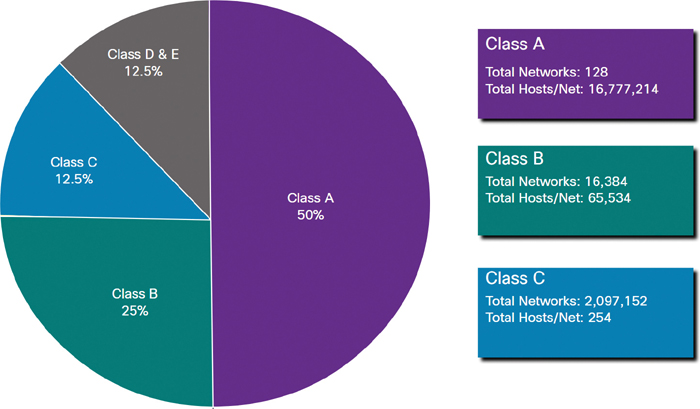
Figure 11-12 Classful Addressing
In the mid-1990s, with the introduction of the World Wide Web (WWW), classful addressing was deprecated to more efficiently allocate the limited IPv4 address space. Classful address allocation was replaced with classless addressing, which is used today. Classless addressing ignores the rules of classes (A, B, C). Public IPv4 network addresses (network addresses and subnet masks) are allocated based on the number of addresses that can be justified.
Assignment of IP Addresses (11.3.6)
Public IPv4 addresses are addresses that are globally routed over the internet. Public IPv4 addresses must be unique.
Both IPv4 and IPv6 addresses are managed by the Internet Assigned Numbers Authority (IANA). IANA manages and allocates blocks of IP addresses to the Regional Internet Registries (RIRs). The five RIRs are shown in Figure 11-13.
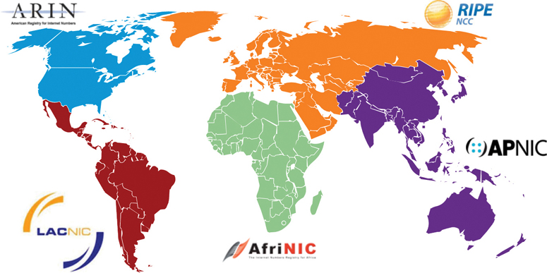
Figure 11-13 Five Regional Internet Registries
RIRs are responsible for allocating IP addresses to ISPs that provide IPv4 address blocks to organizations and smaller ISPs. Organizations can also get their addresses directly from an RIR (subject to the policies of that RIR).
The five RIRs are as follows:
AfriNIC (African Network Information Centre): Africa region
APNIC (Asia Pacific Network Information Centre): Asia/Pacific region
ARIN (American Registry for Internet Numbers): North America region
LACNIC (Regional Latin-American and Caribbean IP Address Registry): Latin America and some Caribbean islands
RIPE NCC (Réseaux IP Européens Network Coordination Centre): Europe, the Middle East, and Central Asia
Activity—Public or Private IPv4 Address (11.3.7)
Refer to the online course to complete this activity.
Check Your Understanding—Types of IPv4 Addresses (11.3.8)
Refer to the online course to complete this activity.
Network Segmentation (11.4)
This section discusses network segmentation and the reasons we divide larger networks into smaller networks known as subnets.
Broadcast Domains and Segmentation (11.4.1)
Have you ever received an email that was addressed to every person at your work or school? That was a broadcast email, and hopefully, it contained information that each of you needed to know. But often a broadcast is not really pertinent to everyone on the mailing list. Sometimes, only a segment of the population needs to read the information sent as a broadcast.
In an Ethernet LAN, devices use broadcasts and Address Resolution Protocol (ARP) to locate other devices. ARP sends Layer 2 broadcasts to a known IPv4 address on the local network to discover the associated MAC address. Devices on Ethernet LANs also locate other devices using services. A host typically acquires its IPv4 address configuration by using the Dynamic Host Configuration Protocol (DHCP), which sends broadcasts on the local network to locate a DHCP server.
A switch propagates a broadcast out all interfaces except the interface on which it was received. For example, if a switch in Figure 11-14 were to receive a broadcast, it would forward it to the other switches and other users connected in the network.
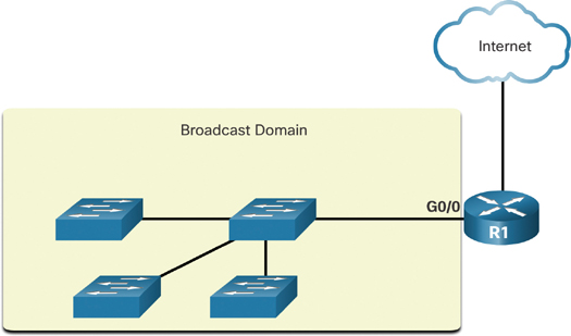
Figure 11-14 Broadcast Domain with Four Switches
Routers do not propagate broadcasts. When a router receives a broadcast, it does not forward it out other interfaces. For instance, when R1 receives a broadcast on its Gigabit Ethernet 0/0 interface, it does not forward out another interface.
Therefore, each router interface connects to a broadcast domain, and broadcasts are propagated only within that specific broadcast domain.
Problems with Large Broadcast Domains (11.4.2)
A large broadcast domain is a network that connects many hosts. A problem with a large broadcast domain is that these hosts can generate excessive broadcasts and can negatively affect the network. In Figure 11-15, LAN 1 connects 400 users that could generate an excess amount of broadcast traffic. The significant amount of traffic this setup can cause results in slow network operations and also in slow device operations because a device must accept and process each broadcast packet.
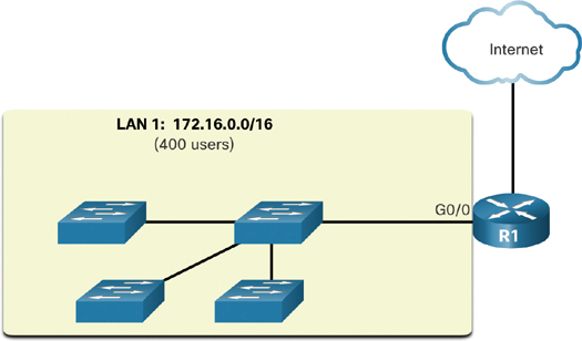
Figure 11-15 Large Broadcast Domain
The solution is to reduce the size of the network to create smaller broadcast domains in a process called subnetting. These smaller network spaces are called subnets.
In Figure 11-16, the 400 users in LAN 1 with network address 172.16.0.0/16 have been divided into two subnets of 200 users each: 172.16.0.0/24 and 172.16.1.0/24. Now broadcasts are propagated only within the smaller broadcast domains. Therefore, a broadcast in LAN 1 would not propagate to LAN 2.

Figure 11-16 Segmenting a Large Broadcast Domain
Notice that the prefix length has changed from a single /16 network to two /24 networks. This is the basis of subnetting: using host bits to create additional subnets.
Note
The terms subnet and network are often used interchangeably. In most cases, a network is a subnet of some larger address block.
Reasons for Segmenting Networks (11.4.3)
Subnetting reduces overall network traffic and improves network performance. It also enables an administrator to implement security policies such as which subnets are allowed or not allowed to communicate together. In addition, subnetting reduces the number of devices affected by abnormal broadcast traffic due to misconfigurations, hardware/software problems, or malicious intent.
There are various ways of using subnets to help manage network devices, as shown in Figures 11-17 through 11-19.

Figure 11-17 Subnetting by Location
Network administrators can create subnets using any other division that makes sense for the network. Notice in Figures 11-17 through 11-19 that the subnets use longer prefix lengths to identify networks.

Figure 11-18 Subnetting by Group or Function
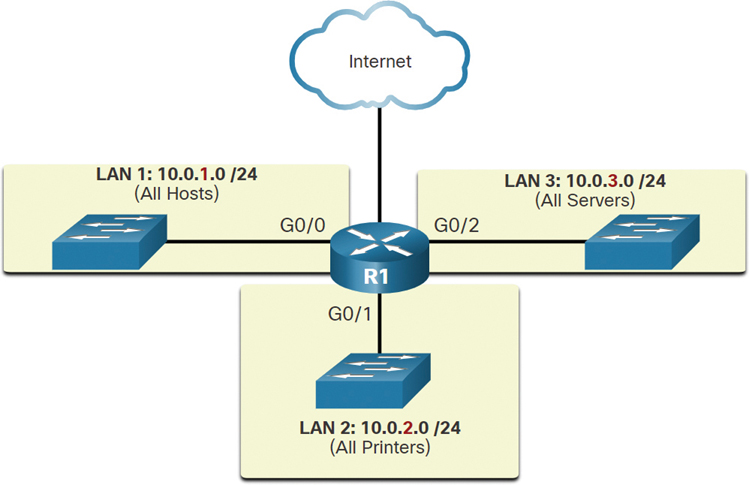
Figure 11-19 Subnetting by Device Type
Understanding how to subnet networks is a fundamental skill that all network administrators must develop. Various methods have been created to help understand this process. Although it may be a little overwhelming at first, pay close attention to the detail and, with practice, subnetting will become easier.
Check Your Understanding—Network Segmentation (11.4.4)
Refer to the online course to complete this activity.
Subnet an IPv4 Network (11.5)
Without subnetting, the performance of an IPv4-based network would quickly decrease as the number of hosts increased. Proper subnetting allows better control of network traffic and greatly improves network efficiency.
Subnet on an Octet Boundary (11.5.1)
In the previous section, you learned several good reasons for segmenting a network. You also learned that segmenting a network is called subnetting. Subnetting is a critical skill to have when administering an IPv4 network. It is a bit daunting at first, but it gets much easier with practice.
IPv4 subnets are created by using one or more of the host bits as network bits. This process involves extending the subnet mask to borrow some of the bits from the host portion of the address to create additional network bits. The more host bits that are borrowed, the more subnets that can be defined. The more bits that are borrowed to increase the number of subnets, the lower the number of hosts per subnet.
Networks are most easily subnetted at an octet boundary: /8, /16, or /24. Table 11-4 identifies these prefix lengths. Notice that using longer prefixes decreases the number of hosts per subnet.
Table 11-4 Subnet Masks on Octet Boundaries
Prefix Length |
Subnet Mask |
Subnet Mask in Binary (n = network, h = host) |
Number of Hosts |
/8 |
255.0.0.0 |
nnnnnnnn.hhhhhhhh.hhhhhhhh.hhhhhhhh 11111111.00000000.00000000.00000000 |
16,777,214 |
/16 |
255.255.0.0 |
nnnnnnnn.nnnnnnnn.hhhhhhhh.hhhhhhhh 11111111.11111111.00000000.00000000 |
65,534 |
/24 |
255.255.255.0 |
nnnnnnnn.nnnnnnnn.nnnnnnnn.hhhhhhhh 11111111.11111111.11111111.00000000 |
254 |
To understand how subnetting on the octet boundary can be useful, consider the following example: Say that an enterprise has chosen the private address 10.0.0.0/8 as its internal network address. That network address can connect 16,777,214 hosts in one broadcast domain. Obviously, having more than 16 million hosts on a single subnet is not ideal.
The enterprise could further subnet the 10.0.0.0/8 address at the octet boundary /16, as shown in Table 11-5. This would enable the enterprise to define up to 256 subnets (that is, 10.0.0.0/16 to 10.255.0.0/16), and each subnet would be capable of connecting 65,534 hosts. Notice that the first two octets identify the network portion of the address, whereas the last two octets are for host IP addresses.
Table 11-5 Subnetting Network 10.0.0.0/8 Using a /16 Prefix
Subnet Address (256 Possible Subnets) |
Host Range (65,534 Possible Hosts per Subnet) |
Broadcast |
10.0.0.0/16 |
10.0.0.1–10.0.255.254 |
10.0.255.255 |
10.1.0.0/16 |
10.1.0.1–10.1.255.254 |
10.1.255.255 |
10.2.0.0/16 |
10.2.0.1–10.2.255.254 |
10.2.255.255 |
10.3.0.0/16 |
10.3.0.1–10.3.255.254 |
10.3.255.255 |
10.4.0.0/16 |
10.4.0.1–10.4.255.254 |
10.4.255.255 |
10.5.0.0/16 |
10.5.0.1–10.5.255.254 |
10.5.255.255 |
10.6.0.0/16 |
10.6.0.1–10.6.255.254 |
10.6.255.255 |
10.7.0.0/16 |
10.7.0.1–10.7.255.254 |
10.7.255.255 |
… |
… |
… |
10.255.0.0/16 |
10.255.0.1–10.255.255.254 |
10.255.255.255 |
Alternatively, the enterprise could choose to subnet the 10.0.0.0/8 network at the /24 octet boundary, as shown in Table 11-6. This would enable the enterprise to define 65,536 subnets, each capable of connecting 254 hosts. The /24 boundary is very popular in subnetting because it accommodates a reasonable number of hosts and conveniently subnets at the octet boundary.
Table 11-6 Subnetting Network 10.0.0.0/8 Using a /24 Prefix
Subnet Address (65,536 Possible Subnets) |
Host Range (254 Possible Hosts per Subnet) |
Broadcast |
10.0.0.0/24 |
10.0.0.1–10.0.0.254 |
10.0.0.255 |
10.0.1.0/24 |
10.0.1.1–10.0.1.254 |
10.0.1.255 |
10.0.2.0/24 |
10.0.2.1–10.0.2.254 |
10.0.2.255 |
… |
… |
… |
10.0.255.0/24 |
10.0.255.1–10.0.255.254 |
10.0.255.255 |
10.1.0.0/24 |
10.1.0.1–10.1.0.254 |
10.1.0.255 |
10.1.1.0/24 |
10.1.1.1–10.1.1.254 |
10.1.1.255 |
10.1.2.0/24 |
10.1.2.1–10.1.2.254 |
10.1.2.255 |
… |
… |
… |
10.100.0.0/24 |
10.100.0.1–10.100.0.254 |
10.100.0.255 |
… |
… |
… |
10.255.255.0/24 |
10.255.255.1–10.2255.255.254 |
10.255.255.255 |
Subnet Within an Octet Boundary (11.5.2)
The examples shown thus far have borrowed host bits from the common /8, /16, and /24 network prefixes. However, subnets can borrow bits from any host bit position to create other masks.
For instance, a /24 network address is commonly subnetted using longer prefixes by borrowing bits from the fourth octet. This provides an administrator with additional flexibility when assigning network addresses to a smaller number of end devices.
Table 11-7 shows six ways to subnet a /24 network.
Table 11-7 Subnetting a /24 Network
Prefix Length |
Subnet Mask |
Subnet Mask in Binary (n = Network, h = Host) |
Number of Subnets |
Number of Hosts |
/25 |
255.255.255.128 |
nnnnnnnn.nnnnnnnn.nnnnnnnn.nhhhhhhh 11111111.11111111.11111111.10000000 |
2 |
126 |
/26 |
255.255.255.192 |
nnnnnnnn.nnnnnnnn.nnnnnnnn.nnhhhhhh 11111111.11111111.11111111.11000000 |
4 |
62 |
/27 |
255.255.255.224 |
nnnnnnnn.nnnnnnnn.nnnnnnnn.nnnhhhhh 11111111.11111111.11111111.11100000 |
8 |
30 |
/28 |
255.255.255.240 |
nnnnnnnn.nnnnnnnn.nnnnnnnn.nnnnhhhh 11111111.11111111.11111111.11110000 |
16 |
14 |
/29 |
255.255.255.248 |
nnnnnnnn.nnnnnnnn.nnnnnnnn.nnnnnhhh 11111111.11111111.11111111.11111000 |
32 |
6 |
/30 |
255.255.255.252 |
nnnnnnnn.nnnnnnnn.nnnnnnnn.nnnnnnhh 11111111.11111111.11111111.11111100 |
64 |
2 |
For each bit borrowed from the fourth octet, the number of subnetworks available is doubled, and the number of host addresses per subnet is reduced:
/25 row: Borrowing 1 bit from the fourth octet creates 2 subnets supporting 126 hosts each.
/26 row: Borrowing 2 bits creates 4 subnets supporting 62 hosts each.
/27 row: Borrowing 3 bits creates 8 subnets supporting 30 hosts each.
/28 row: Borrowing 4 bits creates 16 subnets supporting 14 hosts each.
/29 row: Borrowing 5 bits creates 32 subnets supporting 6 hosts each.
/30 row: Borrowing 6 bits creates 64 subnets supporting 2 hosts each.
Video—The Subnet Mask (11.5.3)
Refer to the online course to view this video.
Video—Subnet with the Magic Number (11.5.4)
Refer to the online course to view this video.
Packet Tracer—Subnet an IPv4 Network (11.5.5)

In this activity, starting from a single network address and network mask, you will subnet the Customer network into multiple subnets. The subnetting scheme should be based on the number of host computers required in each subnet, as well as other network considerations, such as future network host expansion.
After you have created a subnetting scheme and completed the table by filling in the missing host and interface IP addresses, you will configure the host PCs, switches, and router interfaces.
After the network devices and host PCs have been configured, you will use the ping command to test for network connectivity.
Subnet a Slash 16 and a Slash 8 Prefix (11.6)
This section discusses and gives examples of subnetting networks that have /16 and /8 prefix lengths.
Create Subnets with a Slash 16 Prefix (11.6.1)
Some subnetting is easier than other subnetting. This section explains how to create subnets that each have the same number of hosts.
In a situation requiring a larger number of subnets, an IPv4 network is required that has more hosts bits available to borrow. For example, the network address 172.16.0.0 has a default mask of 255.255.0.0, or /16. This address has 16 bits in the network portion and 16 bits in the host portion. The 16 bits in the host portion are available to borrow for creating subnets. Table 11-8 highlights all the possible scenarios for subnetting a /16 prefix.
Table 11-8 Subnet a /16 Network
Prefix Length |
Subnet Mask |
Network Address (n = Network, h = Host) |
Number of Subnets |
Number of Hosts |
/17 |
255.255.128.0 |
nnnnnnnn.nnnnnnnn.nhhhhhhh.hhhhhhhh 11111111.11111111.10000000.00000000 |
2 |
32766 |
/18 |
255.255.192.0 |
nnnnnnnn.nnnnnnnn.nnhhhhhh.hhhhhhhh 11111111.11111111.11000000.00000000 |
4 |
16382 |
/19 |
255.255.224.0 |
nnnnnnnn.nnnnnnnn.nnnhhhhh.hhhhhhhh 11111111.11111111.11100000.00000000 |
8 |
8190 |
/20 |
255.255.240.0 |
nnnnnnnn.nnnnnnnn.nnnnhhhh.hhhhhhhh 11111111.11111111.11110000.00000000 |
16 |
4094 |
/21 |
255.255.248.0 |
nnnnnnnn.nnnnnnnn.nnnnnhhh.hhhhhhhh 11111111.11111111.11111000.00000000 |
32 |
2046 |
/22 |
255.255.252.0 |
nnnnnnnn.nnnnnnnn.nnnnnnhh.hhhhhhhh 11111111.11111111.11111100.00000000 |
64 |
1022 |
/23 |
255.255.254.0 |
nnnnnnnn.nnnnnnnn.nnnnnnnh.hhhhhhhh 11111111.11111111.11111110.00000000 |
128 |
510 |
/24 |
255.255.255.0 |
nnnnnnnn.nnnnnnnn.nnnnnnnn.hhhhhhhh 11111111.11111111.11111111.00000000 |
256 |
254 |
/25 |
255.255.255.128 |
nnnnnnnn.nnnnnnnn.nnnnnnnn.nhhhhhhh 11111111.11111111.11111111.10000000 |
512 |
126 |
/26 |
255.255.255.192 |
nnnnnnnn.nnnnnnnn.nnnnnnnn.nnhhhhhh 11111111.11111111.11111111.11000000 |
1024 |
62 |
/27 |
255.255.255.224 |
nnnnnnnn.nnnnnnnn.nnnnnnnn.nnnhhhhh 11111111.11111111.11111111.11100000 |
2048 |
30 |
/28 |
255.255.255.240 |
nnnnnnnn.nnnnnnnn.nnnnnnnn.nnnnhhhh 11111111.11111111.11111111.11110000 |
4096 |
14 |
/29 |
255.255.255.248 |
nnnnnnnn.nnnnnnnn.nnnnnnnn.nnnnnhhh 11111111.11111111.11111111.11111000 |
8192 |
6 |
/30 |
255.255.255.252 |
nnnnnnnn.nnnnnnnn.nnnnnnnn.nnnnnnhh 11111111.11111111.11111111.11111100 |
16384 |
2 |
Although you do not need to memorize this table, you do need to have a good understanding of how each value in the table is generated. Do not let the size of the table intimidate you. It is big because it has 8 additional bits that can be borrowed, and, therefore, the numbers of subnets and hosts are simply larger.
Create 100 Subnets with a Slash 16 Prefix (11.6.2)
Consider a large enterprise that requires at least 100 subnets and that has chosen the private address 172.16.0.0/16 as its internal network address.
When borrowing bits from a /16 address, start borrowing bits in the third octet, going from left to right. Borrow a single bit at a time until the number of bits necessary to create 100 subnets is reached.
Figure 11-20 displays the number of subnets that can be created when borrowing bits from the third octet and the fourth octet. Notice that there are now up to 14 host bits that can be borrowed.
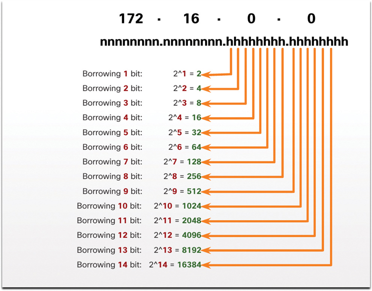
Figure 11-20 Number of Subnets Created
To satisfy the requirement of 100 subnets for the enterprise, 7 bits (that is, 27 = 128 subnets) would need to be borrowed (for a total of 128 subnets), as shown in Figure 11-21.
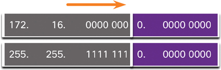
Figure 11-21 172.16.0.0/23 Network
Recall that the subnet mask must change to reflect the borrowed bits. In this example, when 7 bits are borrowed, the mask is extended 7 bits into the third octet. In decimal, the mask is represented as 255.255.254.0, or a /23 prefix, because the third octet is 11111110 in binary, and the fourth octet is 00000000 in binary.
Figure 11-22 shows the resulting subnets, from 172.16.0.0/23 up to 172.16.254.0/23.
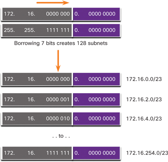
Figure 11-22 Resulting /23 Subnets
After borrowing 7 bits for the subnet, there is 1 host bit remaining in the third octet, and there are 8 host bits remaining in the fourth octet, for a total of 9 bits not borrowed. 29 results in 512 total host addresses. The first address is reserved for the network address, and the last address is reserved for the broadcast address, so subtracting for these two addresses (29 – 2) leaves 510 available host addresses for each /23 subnet.
As shown in Figure 11-23, the first host address for the first subnet is 172.16.0.1, and the last host address is 172.16.1.254.
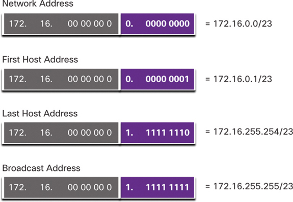
Figure 11-23 Address Range for the 172.16.0.0/23 Subnet
Create 1000 Subnets with a Slash 8 Prefix (11.6.3)
Some organizations, such as small service providers or large enterprises, may need even more than 100 subnets. For example, a small ISP may need 1000 subnets for its clients. Each client needs plenty of space in the host portion to create its own subnets.
Say that an ISP has a network address 10.0.0.0 255.0.0.0, or 10.0.0.0/8. This means there are 8 bits in the network portion and 24 host bits available to borrow toward subnetting. Therefore, the small ISP will subnet the 10.0.0.0/8 network.
To create subnets, you must borrow bits from the host portion of the IPv4 address of the existing internetwork. Starting from the left at the first available host bit, borrow a single bit at a time until you reach the number of bits necessary to create 1000 subnets. As shown in Figure 11-24, you need to borrow 10 bits to create 1024 subnets (210 = 1024). You end up borrowing 8 bits from the second octet and 2 additional bits from the third octet.
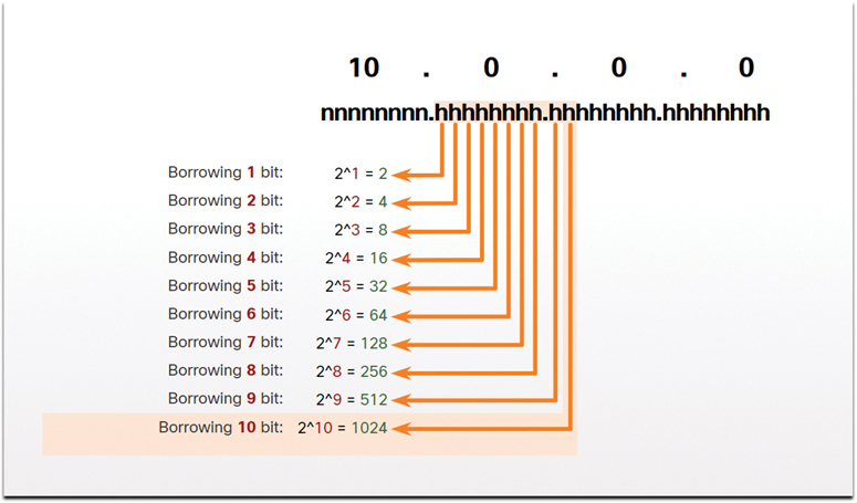
Figure 11-24 Number of Subnets Created
Figure 11-25 shows the network address and the resulting subnet mask, which converts to 255.255.192.0, or 10.0.0.0/18.
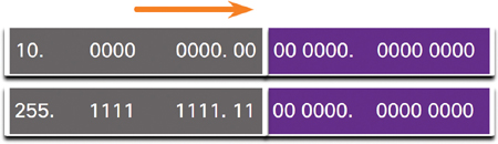
Figure 11-25 10.0.0.0/18 Network
Figure 11-26 displays the subnets resulting from borrowing 10 bits, creating subnets from 10.0.0.0/18 to 10.255.128.0/18.
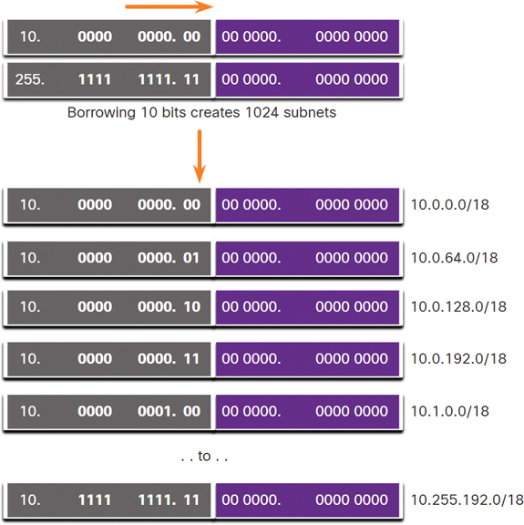
Figure 11-26 Resulting /18 Subnets
Borrowing 10 bits to create the subnets leaves 14 host bits for each subnet. Subtracting 2 hosts per subnet (1 for the network address and 1 for the broadcast address) leaves 214 – 2 = 16,382 hosts per subnet. This means that each of the 1000 subnets can support up to 16,382 hosts.
Figure 11-27 shows the specifics of the first subnet.
Video—Subnet Across Multiple Octets (11.6.4)
Refer to the online course to view this video.
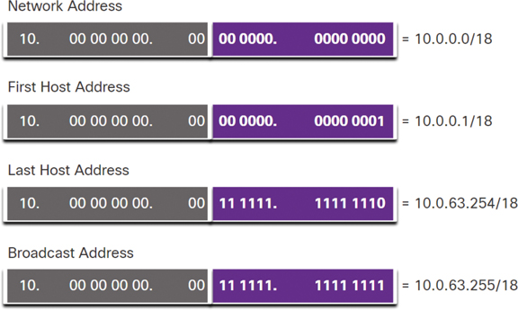
Figure 11-27 Address Range for the 10.0.0.0/18 Subnet
Activity—Calculate the Subnet Mask (11.6.5)
Refer to the online course to complete this activity.
Lab—Calculate IPv4 Subnets (11.6.6)
In this lab, you will complete the following objectives:
Part 1: Determine IPv4 Address Subnetting
Part 2: Calculate IPv4 Address Subnetting
Subnet to Meet Requirements (11.7)
This section discusses the differences between subnetting areas of a network that use private IPv4 address space and areas that use public IPv4 address space. Although the technique of subnetting is the same, there are some important considerations.
Subnet Private Versus Public IPv4 Address Space (11.7.1)
Your organization’s network may use both public and private IPv4 addresses. This affects how you will subnet your network.
Figure 11-28 shows a typical enterprise network, which includes the following components:

Figure 11-28 Intranet and DMZ in an Enterprise Network
Intranet: This is the internal part of a company’s network, accessible only within the organization. Devices in the intranet use private IPv4 addresses.
DMZ: This is part of the company’s network containing resources available to the internet, such as a web server. Devices in the DMZ use public IPv4 addresses.
The intranet and the DMZ have unique subnetting requirements and challenges.
The intranet uses private IPv4 addressing space. This means the organization can use any of the private IPv4 network addresses, including the 10.0.0.0/8 prefix, with 24 host bits and more than 16 million hosts. Using a network address with 24 host bits makes subnetting easier and more flexible. This includes subnetting on an octet boundary using a subnet mask of /16 or /24.
For example, the private IPv4 network address 10.0.0.0/8 can be subnetted using a /16 mask. As shown in Table 11-9, this results in 256 subnets, with 65,534 hosts per subnet. If an organization has a need for fewer than 200 subnets, allowing for some growth, this gives each subnet more than enough host addresses.
Table 11-9 Subnetting Network 10.0.0.0/8 Using a /16 Prefix
Subnet Address (256 Possible Subnets) |
Host Range (65,534 Possible Hosts per Subnet) |
Broadcast |
10.0.0.0/16 |
10.0.0.1–10.0.255.254 |
10.0.255.255 |
10.1.0.0/16 |
10.1.0.1–10.1.255.254 |
10.1.255.255 |
10.2.0.0/16 |
10.2.0.1–10.2.255.254 |
10.2.255.255 |
10.3.0.0/16 |
10.3.0.1–10.3.255.254 |
10.3.255.255 |
10.4.0.0/16 |
10.4.0.1–10.4.255.254 |
10.4.255.255 |
10.5.0.0/16 |
10.5.0.1–10.5.255.254 |
10.5.255.255 |
10.6.0.0/16 |
10.6.0.1–10.6.255.254 |
10.6.255.255 |
10.7.0.0/16 |
10.7.0.1–10.7.255.254 |
10.7.255.255 |
… |
… |
… |
10.255.0.0/16 |
10.255.0.1–10.255.255.254 |
10.255.255.255 |
Another option using the 10.0.0.0/8 private IPv4 network address is to subnet using a /24 mask. As shown in Table 11-10, this results in 65,536 subnets, with 254 hosts per subnet. If an organization needs more than 256 subnets, then a /24 mask can be used, with 254 hosts per subnet.
Table 11-10 Subnetting Network 10.0.0.0/8 Using a /24 Prefix
Subnet Address (65,536 Possible Subnets) |
Host Range (254 Possible Hosts per Subnet) |
Broadcast |
10.0.0.0/24 |
10.0.0.1–10.0.0.254 |
10.0.0.255 |
10.0.1.0/24 |
10.0.1.1–10.0.1.254 |
10.0.1.255 |
10.0.2.0/24 |
10.0.2.1–10.0.2.254 |
10.0.2.255 |
… |
… |
… |
10.0.255.0/24 |
10.0.255.1–10.0.255.254 |
10.0.255.255 |
10.1.0.0/24 |
10.1.0.1–10.1.0.254 |
10.1.0.255 |
10.1.1.0/24 |
10.1.1.1–10.1.1.254 |
10.1.1.255 |
10.1.2.0/24 |
10.1.2.1–10.1.2.254 |
10.1.2.255 |
… |
… |
… |
10.100.0.0/24 |
10.100.0.1–10.100.0.254 |
10.100.0.255 |
… |
… |
… |
10.255.255.0/24 |
10.255.255.1–10.2255.255.254 |
10.255.255.255 |
The 10.0.0.0/8 network can also be subnetted using any other number of prefix lengths, such as /12, /18, /20, and so on, which gives the network administrator a wide variety of options. Using a 10.0.0.0/8 private IPv4 network address makes subnet planning and implementation easy.
What About the DMZ?
Because the devices in the DMZ need to be publicly accessible from the internet, these devices require public IPv4 addresses. The depletion of public IPv4 address space became an issue beginning in the mid-1990s. Since 2011, IANA and four out of the five RIRs have run out of IPv4 address space. Although organizations are making the transition to IPv6, the remaining IPv4 address space remains severely limited. This means an organization must maximize its own limited number of public IPv4 addresses; the network administrator must therefore subnet the network’s public address space into subnets with different subnet masks in order to minimize the number of unused host addresses per subnet. This is known as variable-length subnet masking (VLSM).
Minimize Unused Host IPv4 Addresses and Maximize Subnets (11.7.2)
To minimize the number of unused host IPv4 addresses and maximize the number of available subnets, there are two considerations when planning subnets: the number of host addresses required for each network and the number of individual subnets needed.
Table 11-11 displays the specifics for subnetting a /24 network. Notice that there is an inverse relationship between the number of subnets and the number of hosts. The more bits that are borrowed to create subnets, the fewer host bits remain available. If more host addresses are needed, more host bits are required, resulting in fewer subnets.
The number of host addresses required in the largest subnet determines how many bits must be left in the host portion. Recall that two of the addresses cannot be used, so the usable number of addresses can be calculated as 2n – 2.
Table 11-11 Subnetting a /24 Network
Prefix Length |
Subnet Mask |
Subnet Mask in Binary (n = Network, h = Host) |
Number of Subnets |
Number of Hosts per Subnet |
/25 |
255.255.255.128 |
nnnnnnnn.nnnnnnnn.nnnnnnnn.nhhhhhhh 11111111.11111111.11111111.10000000 |
2 |
126 |
/26 |
255.255.255.192 |
nnnnnnnn.nnnnnnnn.nnnnnnnn.nnhhhhh 11111111.11111111.11111111.11000000 |
4 |
62 |
/27 |
255.255.255.224 |
nnnnnnnn.nnnnnnnn.nnnnnnnn.nnnhhhh 11111111.11111111.11111111.11100000 |
8 |
30 |
/28 |
255.255.255.240 |
nnnnnnnn.nnnnnnnn.nnnnnnnn.nnnnhhh 11111111.11111111.11111111.11110000 |
16 |
14 |
/29 |
255.255.255.248 |
nnnnnnnn.nnnnnnnn.nnnnnnnn.nnnnnhh 11111111.11111111.11111111.11111000 |
32 |
6 |
/30 |
255.255.255.252 |
nnnnnnnn.nnnnnnnn.nnnnnnnn.nnnnnnh 11111111.11111111.11111111.11111100 |
64 |
2 |
Network administrators must devise a network addressing scheme that accommodates the maximum number of hosts for each network and the number of subnets. The addressing scheme should allow for growth in both the number of host addresses per subnet and the total number of subnets.
Example: Efficient IPv4 Subnetting (11.7.3)
In this example, an ISP has allocated a corporate headquarters the public network address 172.16.0.0/22 (with 10 host bits). As shown in Figure 11-29, this address provides 1022 host addresses.
Note
172.16.0.0/22 is part of the IPv4 private address space; it is not an actual public IPv4 address.
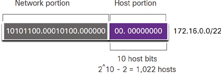
Figure 11-29 Network Address
The corporate headquarters has a DMZ and four branch offices, each needing its own public IPv4 address space. Corporate headquarters needs to make the best use of its limited IPv4 address space.
The topology shown in Figure 11-30 consists of five sites: a corporate office and four branch sites. Each site requires internet connectivity and, therefore, five internet connections. This means that the organization requires 10 subnets from the company’s 172.16.0.0/22 public address. The largest subnet requires 40 addresses.
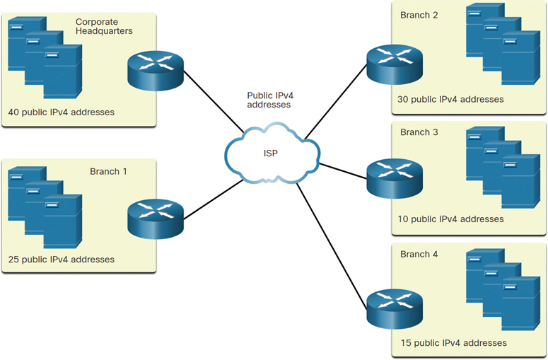
Figure 11-30 Corporate Topology with Five Sites
The 172.16.0.0/22 network address has 10 host bits, as shown in Figure 11-31. Because the largest subnet requires 40 hosts, the administrator needs a minimum of 6 host bits to provide addressing for 40 hosts. (This is determined by using the formula 26 – 2 = 62 hosts.)
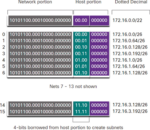
Figure 11-31 Subnet Scheme
Using the formula for determining subnets results in 16 subnets (that is, 24 = 16). The internetwork in this example requires 10 subnets, so this will meet the requirement and allow for some additional growth.
In this case, the first 4 host bits can be used to allocate subnets. This means 2 bits from the third octet and 2 bits from the fourth octet will be borrowed. When 4 bits are borrowed from the 172.16.0.0/22 network, the new prefix length is /26, with a subnet mask of 255.255.255.192.
As shown in Figure 11-32, the subnets can be assigned to each location and router-to-ISP connections.
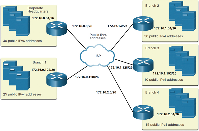
Figure 11-32 Subnet Assignments to Each Site and the ISP
Activity—Determine the Number of Bits to Borrow (11.7.4)
Refer to the online course to complete this activity.
Packet Tracer—Subnetting Scenario (11.7.5)
In this activity, you need to subnet the network address 192.168.100.0/24 and provide the IP addressing for the network shown in the topology. Each LAN in the network requires enough space for at least 25 addresses; this includes end devices as well as the switch and the router. The connection between R1 to R2 will require an IP address for each end of the link.
VLSM (11.8)
This section discusses a technique called variable-length subnet masking (VLSM) that can be used to subnet a subnet. VLSM is typically used to help conserve IPv4 address space.
Video—VLSM Basics (11.8.1)
As mentioned in the previous section, public and private addresses affect the way you subnet a network. There are also other issues that affect subnetting schemes. A standard /16 subnetting scheme creates subnets that each have the same number of hosts. Not every subnet you create will need this many hosts, and many IPv4 addresses will be unused. Perhaps you will need one subnet that contains many more hosts. This is why variable-length subnet masking (VLSM) was developed.
Refer to the online course to view this video.
Video—VLSM Example (11.8.2)
Refer to the online course to view this video.
IPv4 Address Conservation (11.8.3)
Due to the depletion of public IPv4 address space, making the most out of the available host addresses is a primary concern when subnetting IPv4 networks.
Note
The larger IPv6 address allows for much easier address planning and allocation than IPv4 allows. Conserving IPv6 addresses is not an issue. This is one of the driving forces for transitioning to IPv6.
Using traditional subnetting, the same number of addresses is allocated for each subnet. If all the subnets have the same requirements for the number of hosts, or if conserving IPv4 address space is not an issue, these fixed-size address blocks are efficient. However, with public IPv4 addresses, that is typically not the case. For example, the topology shown in Figure 11-33 requires seven subnets: one for each of the four LANs and one for each of the three connections between the routers.
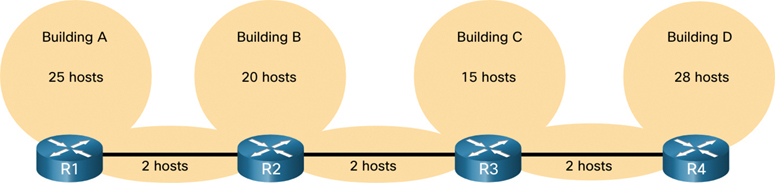
Figure 11-33 Topology Example for IPv4 Addressing
Using traditional subnetting with the address 192.168.20.0/24, 3 bits can be borrowed from the host portion in the last octet to meet the subnet requirement of seven subnets. As shown in Figure 11-34, borrowing 3 bits creates eight subnets and leaves 5 host bits with 30 usable hosts per subnet. This scheme creates the needed subnets and meets the host requirement of the largest LAN.
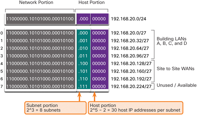
Figure 11-34 Basic Subnetting Scheme
These seven subnets could be assigned to the LAN and WAN networks, as shown in Figure 11-35.
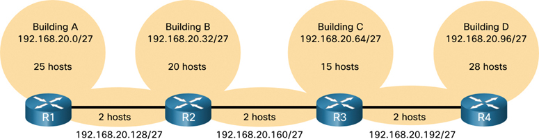
Figure 11-35 IPv4 Addresses Assigned with a /27 Subnet Mask
Although this traditional subnetting meets the needs of the largest LAN and divides the address space into an adequate number of subnets, it results in significant waste of unused addresses.
For example, only two addresses are needed in each subnet for the three WAN links. Because each subnet has 30 usable addresses, there are 28 unused addresses in each of these subnets. As shown in Figure 11-36, this results in 84 unused addresses (that is, 28 × 3).
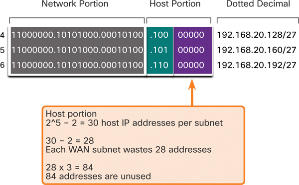
Figure 11-36 Unused Addresses on WAN Subnets
Furthermore, this scheme limits future growth by reducing the total number of subnets available. This inefficient use of addresses is characteristic of traditional subnetting. Applying a traditional subnetting scheme to this scenario is not very efficient and is wasteful.
Variable-length subnet masking (VLSM) was developed to avoid wasting addresses by making it possible to subnet a subnet.
VLSM (11.8.4)
In all the previous subnetting examples, the same subnet mask was applied for all the subnets. This means that each subnet has the same number of available host addresses. As illustrated on the left side of Figure 11-37, traditional subnetting creates subnets of equal size. Each subnet in a traditional scheme uses the same subnet mask. As shown in the right side of the figure, VLSM allows a network space to be divided into unequal parts. With VLSM, the subnet mask varies depending on how many bits have been borrowed for a particular subnet—hence the variable part of the VLSM.
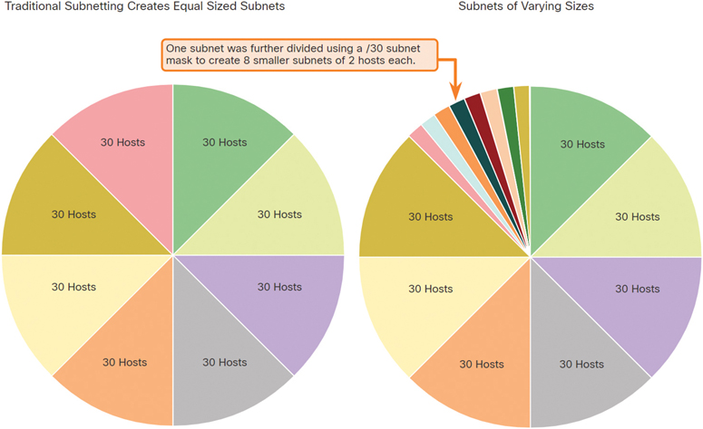
Figure 11-37 Traditional Subnetting Versus VLSM
VLSM is just subnetting a subnet. The same topology used previously is shown in Figure 11-38. In this case, we again use the 192.168.20.0/24 network and subnet it for seven subnets: one for each of the four LANs and one for each of the three connections between the routers.
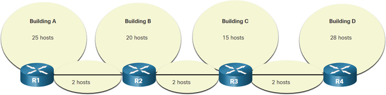
Figure 11-38 Topology Example for IPv4 Addressing
Figure 11-39 shows network 192.168.20.0/24 subnetted into eight equal-sized subnets with 30 usable host addresses per subnet. Four subnets are used for the LANs, and three subnets could be used for the connections between the routers.
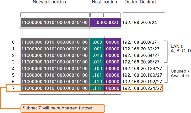
Figure 11-39 Basic Subnetting Scheme
However, the connections between the routers require only 2 host addresses per subnet (1 host address for each router interface). Currently all subnets have 30 usable host addresses per subnet. To avoid wasting 28 addresses per subnet, VLSM can be used to create smaller subnets for the inter-router connections.
To create smaller subnets for the inter-router links, one of the subnets will be divided. In this example, the last subnet, 192.168.20.224/27, will be further subnetted. Figure 11-40 shows the last subnet subnetted further by using the subnet mask 255.255.255.252, or /30.
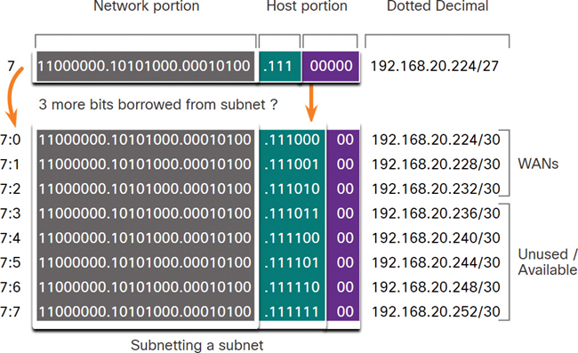
Figure 11-40 VLSM Subnetting Scheme
Why /30? Recall that when the number of needed host addresses is known, the formula 2n – 2 (where n equals the number of host bits remaining) can be used. To provide two usable addresses, 2 host bits must be left in the host portion.
Because there are 5 host bits in the subnetted 192.168.20.224/27 address space, 3 more bits can be borrowed, leaving 2 bits in the host portion. The calculations at this point are exactly the same as those used for traditional subnetting. The bits are borrowed, and the subnet ranges are determined. Figure 11-41 shows how the four /27 subnets have been assigned to the LANs and three of the /30 subnets have been assigned to the inter-router links.
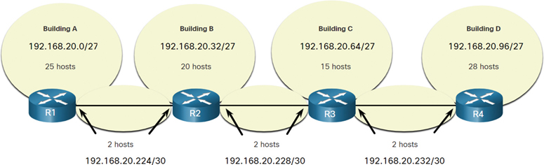
Figure 11-41 VLSM Addressing Scheme Assigned to Networks
This VLSM subnetting scheme reduces the number of addresses per subnet to a size appropriate for the networks that require fewer subnets. Subnetting subnet 7 for inter-router links allows subnets 4, 5, and 6 to be available for future networks and makes five additional subnets available for inter-router connections.
Note
When using VLSM, always begin by satisfying the host requirements of the largest subnet. Continue subnetting until the host requirements of the smallest subnet are satisfied.
VLSM Topology Address Assignment (11.8.5)
Using the VLSM subnets, the LAN and inter-router networks can be addressed without unnecessary waste.
Figure 11-42 shows the network address assignments and the IPv4 addresses assigned to the router interfaces.

Figure 11-42 IPv4 Addresses Assigned to Interfaces
Using a common addressing scheme, the first host IPv4 address for each subnet is assigned to the LAN interface of the router. Hosts on each subnet will have a host IPv4 address from the range of host addresses for that subnet and an appropriate mask. Hosts will use the address of the attached router LAN interface as the default gateway address.
Table 11-12 shows the network addresses and the range of host addresses for each network. The default gateway address is displayed for each of the four LANs.
Table 11-12 VLSM Addressing Table
|
Network Address |
Range of Host Addresses |
Default Gateway Address |
Building A |
192.168.20.0/27 |
192.168.20.1/27–192.168.20.30/27 |
192.168.20.1/27 |
Building B |
192.168.20.32/27 |
192.168.20.33/27–192.168.20.62/27 |
192.168.20.33/27 |
Building C |
192.168.20.64/27 |
192.168.20.65/27–192.168.20.94/27 |
192.168.20.65/27 |
Building D |
192.168.20.96/27 |
192.168.20.97/27–192.168.20.126/27 |
192.168.20.97/27 |
R1–R2 |
192.168.20.224/30 |
192.168.20.225/30–192.168.20.226/30 |
|
R2–R3 |
192.168.20.228/30 |
192.168.20.229/30–192.168.20.230/30 |
|
R3–R4 |
192.168.20.232/30 |
192.168.20.233/30–192.168.20.234/30 |
|
Activity—VLSM Practice (11.8.6)
Refer to the online course to complete this activity.
Structured Design (11.9)
To accommodate all the current and future devices that need IP address, it is necessary to develop a plan and an addressing schema that meets the requirements of the network.
IPv4 Network Address Planning (11.9.1)
Before you start subnetting, you should develop an IPv4 addressing schema for your entire network. You must determine how many subnets you need, how many hosts a particular subnet requires, what devices are part of the subnet, which parts of your network use private addresses and which use public, and many other factors. A good addressing scheme allows for growth. A good addressing scheme is also the sign of a good network administrator.
Planning IPv4 network subnets requires you to examine both the needs of an organization’s network usage and how the subnets will be structured. Performing a network requirement study is the starting point. This means looking at the entire network—both the intranet and the DMZ—and determining how each area will be segmented. The address plan includes determining where address conservation is needed (usually in the DMZ) and where there is more flexibility (usually in the intranet).
Where address conservation is required, the plan should determine how many subnets are needed and how many hosts per subnet are needed. As discussed earlier, conservation is usually required for public IPv4 address space within the DMZ, and it can often be addressed by using VLSM.
Address conservation is usually less of an issue in the corporate intranet than in the DMZ. This is largely due to the fact that private IPv4 addressing, including 10.0.0.0/8, provides more than 16 million host IPv4 addresses.
For most organizations, private IPv4 addresses allow for more than enough internal (intranet) addresses. For many larger organizations and ISPs, even private IPv4 address space is not large enough to accommodate the internal needs. This is another reason organizations are transitioning to IPv6.
For intranets that use private IPv4 addresses and DMZs that use public IPv4 addresses, address planning and assignment are important.
An address plan should typically include a determination of the needs of each subnet in terms of size. How many hosts will there be per subnet? The address plan also needs to include how host addresses will be assigned, which hosts will require static IPv4 addresses, and which hosts can use DHCP for obtaining their addressing information. This will also help prevent duplication of addresses, while allowing for monitoring and management of addresses for performance and security reasons.
Knowing your IPv4 address requirements will help you determine the range, or ranges, of host addresses to implement and help ensure that there are enough addresses to cover your network needs.
Device Address Assignment (11.9.2)
Within a network, different types of devices require addresses:
End-user clients: Most networks allocate IPv4 addresses to client devices dynamically, using Dynamic Host Configuration Protocol (DHCP). This reduces the burden on network support staff and virtually eliminates entry errors. With DHCP, addresses are only leased for a period of time, and they can be reused when the lease expires. This is an important feature for networks that support transient users and wireless devices. Changing the subnetting scheme means that the DHCP server needs to be reconfigured, and the clients must renew their IPv4 addresses. IPv6 clients can obtain address information by using DHCPv6 or SLAAC.
Servers and peripherals: Each server or peripheral should have a predictable static IP address. Use a consistent numbering system for these devices.
Servers that are accessible from the internet: Any server that needs to be publicly available on the internet must have a public IPv4 address, most often accessed using NAT. In some organizations, internal servers (which are not publicly available) must be made available to remote users. In most cases, these servers are assigned private addresses internally, and the user is required to create a virtual private network (VPN) connection to access the server. This has the same effect as the user accessing the server from a host within the intranet.
Intermediary devices: These devices are assigned addresses for network management, monitoring, and security. Because network administrators need to know how to communicate with intermediary devices, they should have predictable, statically assigned addresses.
The gateway: Routers and firewall devices have an IP address assigned to each interface that serves as the gateway for the hosts in that network. Typically, the router interface uses either the lowest or highest address in the network.
When developing an IP addressing scheme, it is generally recommended that you follow a set pattern for allocating addresses to the various types of devices. Having such conventions benefits administrators when adding and removing devices and when filtering traffic based on IP address, and it also simplifies documentation.
Packet Tracer—VLSM Design and Implementation Practice (11.9.3)
In this activity, you are given a /24 network address to use to design a VLSM addressing scheme. Based on a set of requirements, you will assign subnets and addressing, configure devices, and verify connectivity.
Summary (11.10)
The following is a summary of the topics in the chapter and their corresponding online modules.
IPv4 Addressing Structure
An IPv4 address is a 32-bit hierarchical address that is made up of a network portion and a host portion. The bits in the network portion of the address must be identical for all devices that reside in the same network. The bits in the host portion of the address must be unique to identify a specific host within a network. A host requires a unique IPv4 address and a subnet mask to show the network/host portions of the address. The prefix length is the number of bits set to 1 in the subnet mask. It is written in “slash notation,” which is a / followed by the number of bits set to 1. Logical AND is the comparison of 2 bits. Only a 1 AND 1 produces 1, and any other combination results in 0. Within each network are network addresses, host addresses, and a broadcast address.
IPv4 Unicast, Broadcast, and Multicast
Unicast transmission refers to a device sending a message to one other device in one-to-one communications. A unicast packet is a packet with a destination IP address that is a unicast address, which is the address of a single recipient. Broadcast transmission refers to a device sending a message to all the devices on a network in one-to-all communications. A broadcast packet has a destination IP address with all ones (1s) in the host portion, or 32 one (1) bits. Multicast transmission reduces traffic by allowing a host to send a single packet to a selected set of hosts that subscribe to a multicast group. A multicast packet is a packet with a destination IP address that is a multicast address. IPv4 has reserved the 224.0.0.0 to 239.255.255.255 addresses as a multicast range.
Types of IPv4 Addresses
Public IPv4 addresses are globally routed between ISP routers. Not all available IPv4 addresses can be used on the internet. Blocks of addresses called private addresses are used by most organizations to assign IPv4 addresses to internal hosts. Most internal networks use private IPv4 addresses for addressing all internal devices (in intranets); however, these private addresses are not globally routable. A host can use the loopback address to direct traffic back to itself. Link-local addresses are more commonly known as APIPA addresses, or self-assigned addresses. In 1981, IPv4 addresses were assigned using classful addressing: A, B, or C. Public IPv4 addresses must be unique and are globally routed over the internet. Both IPv4 and IPv6 addresses are managed by IANA, which allocates blocks of IP addresses to the RIRs.
Network Segmentation
In an Ethernet LAN, devices locate other devices by using ARP. A switch propagates a broadcast out all interfaces except the interface on which it was received. Routers do not propagate broadcasts; instead, each router interface connects a broadcast domain, and broadcasts are propagated only within that specific domain. A large broadcast domain is a network that connects many hosts. A problem with a large broadcast domain is that the hosts can generate excessive broadcasts and negatively affect the network. The solution is to reduce the size of the network to create smaller broadcast domains in a process called subnetting. These smaller network spaces are called subnets. Subnetting reduces overall network traffic and improves network performance. An administrator may subnet by location, between networks, or by device type.
Subnet an IPv4 Network
IPv4 subnets are created by using one or more of the host bits as network bits. This is done by extending the subnet mask to borrow some of the bits from the host portion of the address to create additional network bits. The more host bits that are borrowed, the more subnets that can be defined. The more bits that are borrowed to increase the number of subnets, the smaller the number of hosts per subnet. Networks are most easily subnetted at the octet boundaries: /8, /16, and /24. Subnets can borrow bits from any host bit position to create other masks.
Subnet a /16 and a /8 Prefix
A situation requiring a larger number of subnets calls for an IPv4 network that has more host bits available to borrow. To create subnets, you must borrow bits from the host portion of the IPv4 address of the existing internetwork. Starting from the left with the first available host bit, borrow a single bit at a time until you reach the number of bits necessary to create the number of subnets required. When borrowing bits from a /16 address, start borrowing bits in the third octet, going from left to right. The first address is reserved for the network address, and the last address is reserved for the broadcast address.
Subnet to Meet Requirements
A typical enterprise network contains an intranet and a DMZ, both of which have subnetting requirements and challenges. An intranet uses private IPv4 addressing space. The 10.0.0.0/8 network can also be subnetted using any other number of prefix lengths, such as /12, /18, /20, and so on, which means the network administrator has many options. Because devices in the DMZ need to be publicly accessible from the internet, these devices require public IPv4 addresses. An organization must maximize its own limited supply of public IPv4 addresses. To reduce the number of unused host addresses per subnet, a network administrator must subnet the public address space into subnets with different subnet masks. This is known as variable-length subnet masking (VLSM). Administrators must consider how many host addresses are required for each network and how many subnets are needed.
Variable-Length Subnet Masking
Traditional subnetting might meet an organization’s needs for its largest LAN and divide the address space into an adequate number of subnets. But it is also likely to result in significant waste of unused addresses. VLSM allows a network space to be divided into unequal parts. With VLSM, the subnet mask varies depending on how many bits have been borrowed for a particular subnet—hence the variable part of the VLSM. VLSM is just subnetting a subnet. When using VLSM, always begin by satisfying the host requirements of the largest subnet. Continue subnetting until the host requirements of the smallest subnet are satisfied. A subnet always needs to be started on an appropriate bit boundary.
Structured Design
A network administrator should study the network requirements to better plan how IPv4 network subnets will be structured. This means looking at the entire network—both the intranet and the DMZ—and determining how each area will be segmented. The address plan includes determining where address conservation is needed (usually within the DMZ) and where there is more flexibility (usually within the intranet). Where address conservation is required, the plan should determine how many subnets are needed and how many hosts per subnet are needed. As discussed earlier, conservation is usually required for public IPv4 address space within the DMZ, and it can often be addressed by using VLSM. The address plan includes how host addresses will be assigned, which hosts will require static IPv4 addresses, and which hosts can use DHCP for obtaining their addressing information. In a network, different types of devices require addresses: end-user clients, servers and peripherals, servers that are accessible from the internet, intermediary devices, and gateways. When developing an IP addressing scheme, it is generally recommended that you follow a set pattern for allocating addresses to the various types of devices. Having such conventions benefits administrators when adding and removing devices and when filtering traffic based on IP address, and it also simplifies documentation.
Packet Tracer—Design and Implement a VLSM Addressing Scheme (11.10.1)
In this activity, you will design a VLSM addressing scheme based on a network address and host requirements. You will configure addressing on routers, switches, and network hosts:
Design a VLSM IP addressing scheme based on the given requirements.
Configure addressing on network devices and hosts.
Verify IP connectivity.
Troubleshoot connectivity issues, as required.
Lab—Design and Implement a VLSM Addressing Scheme (11.10.2)
In this lab, use the 192.168.33.128/25 network address to develop an addressing scheme for the network displayed in the topology diagram. Use VLSM to meet the IPv4 addressing requirements. After you have designed the VLSM address scheme, you will configure the interfaces on the routers with the appropriate IP address information. The future LANs at BR2 need to have addresses allocated, but no interfaces will be configured at this time.
Practice
The following activities provide practice with the topics introduced in this chapter. The lab is available in the companion Introduction to Networks Labs & Study Guide (CCNAv7) (ISBN 9780136634454). The Packet Tracer activity instructions are also provided in the Labs & Study Guide. The PKA files are available in the online course.
Labs
Lab 11.6.6: Calculate IPv4 Subnets
Lab 11.10.2: Design and Implement a VLSM Addressing Scheme
Packet Tracer Activities
Packet Tracer 11.5.5: Subnet an IPv4 Network
Packet Tracer 11.7.5: Subnetting Scenario
Packet Tracer 11.9.3: VLSM Design and Implementation Practice
Packet Tracer 11.10.1: Design and Implement a VLSM Addressing Scheme
Check Your Understanding Questions
Complete all the review questions listed here to test your understanding of the topics and concepts in this chapter. The appendix “Answers to ‘Check Your Understanding’ Questions” lists the answers.
1. What is the prefix length notation for the subnet mask 255.255.255.224?
/25
/26
/27
/28
2. How many valid host addresses are available on an IPv4 subnet that is configured with a /26 mask?
254
190
192
62
64
3. Which subnet mask would be used if 5 host bits are available?
255.255.255.0
255.255.255.128
255.255.255.224
255.255.255.240
4. A network administrator subnets the 192.168.10.0/24 network into subnets with /26 masks. How many equal-sized subnets are created?
1
2
4
8
16
64
5. What subnet mask is represented by the slash notation /20?
255.255.255.248
255.255.224.0
255.255.240.0
255.255.255.0
255.255.255.192
6. Which statement is true about variable-length subnet masking?
All the subnets are equally sized.
The sizes of subnets may be different, depending on requirements.
Subnets may only be subnetted one additional time.
Bits are returned, rather than borrowed, to create additional subnets.
7. Why does a Layer 3 device perform the ANDing process on a destination IPv4 address and subnet mask?
to identify the broadcast address of the destination network
to identify the host address of the destination host
to identify faulty frames
to identify the network address of the destination network
8. How many usable IPv4 addresses are available on the 192.168.1.0/27 network?
256
254
62
30
16
32
9. Which subnet mask would be used if exactly 4 host bits are available?
255.255.255.224
255.255.255.128
255.255.255.240
255.255.255.248
10. Which of the following are components of an IPv4 address? (Choose two.)
subnet portion
network portion
logical portion
host portion
physical portion
broadcast portion
11. If a network device has a mask of /30, how many IPv4 addresses are available for hosts on this network?
64
8
2
32
16
4
12. What does the IPv4 address 172.17.4.250/24 represent?
network address
multicast address
host address
broadcast address
13. If a network device has a mask of /28, how many IP addresses are available for hosts on this network?
256
254
62
32
16
14
14. What is the purpose of the subnet mask in conjunction with an IPv4 address?
to uniquely identify a host on a network
to identify whether the address is public or private
to determine the subnet to which the host belongs
to mask the IP address to outsiders
15. A network administrator is variably subnetting a network. The smallest subnet has a mask of 255.255.255.224. How many usable host addresses will this subnet provide?
2
6
14
30
62