Be forewarned that you may find this section excessively technical, even if you haven’t already made that objection to other parts of the book. Unfortunately, that’s the nature of the beast—technical climbing is technical. If your eyes tend to glaze over as you wade in, feel free to skip ahead, but realize that the discussion lays the groundwork for many of the points I make that run counter to old-school “wisdom.” The forces encountered while climbing and the best ways of dealing with them are indeed difficult to grasp. Most climbers are hazy about the magnitude of climbing forces and the strength of hardware; they often believe that forces are much higher than they actually are, and they don’t appreciate where in the safety system the highest peak forces appear or, for that matter, from which direction. Uneducated climbers tend to attribute anchor failures to lack of strength or simply bad luck. Worse, climbers may develop untenable confidence born only of the absence of disaster in their recent past. Erroneous and misleading information on climbing forces and anchors appears even in texts by respected authors, contributing to the Scylla and Charybdis of overconfidence or paranoia. Don’t be surprised if you read contradictory material elsewhere.
Might as well dive in by discussing ways of describing mass, force, and weight; getting these tangled up confounds discussions of climbing forces. For scientific work nearly the entire world uses a version of the metric system called the International System of Units, abbreviated SI (from the French Le Système International d’Unités). In the SI scheme, mass (an intrinsic property of matter) is expressed in kilograms. Force, a consequence of mass being accelerated or decelerated, is expressed in units called newtons, named after Sir Isaac himself. In the avoirdupois system used in the United States, things are not so simple, or maybe they’re too simple, especially for those who were dozing in freshman physics class. The avoirdupois system has several schemes with units scaled to particular applications. In the version I’ll use, both mass and force are expressed in pounds. There are other schemes in which mass is expressed in slugs or force in poundals. NASA uses an even screwier system in which force is expressed in pounds and mass in slinches; it was trouble managing conversions of units from this scheme that led to the demise of the Mars Climate Orbiter space mission and tens of millions of dollars, so don’t feel like you’re alone if you find this stuff daunting.
Although Americans express both mass and force in pounds, these are very different things. Confusion centers on the notion of weight. Colloquially “weight” usually means mass. When your doctor puts you on a scale to measure your weight, she does so by balancing your mass with calibrated masses built into the scale. But … when you step on your bathroom scale at home you’re actually measuring force—the force, resulting from your mass being acted upon by the acceleration due to gravity, that’s pressing down on the spring inside your scale. Both scales read the same (unless, like me, you lean to the side of your bathroom scale to shave off a few pounds). In fact, they both read the same even if your weight is read out in kilograms. Confused? Maybe you could be a NASA engineer.
To help keep things straight, I’ll use “pound-force” (lbf) to refer to force. One pound (lb) of mass is approximately 0.4536 kilograms (kg). One pound-force is about 4.448 newtons; one thousand newtons (1 kilonewton, kN) is approximately 224.81 lbf. An apparently stationary object requires a force, expressed in lbf, approximately equal to its mass, expressed in lb, to prevent it from falling into the earth. For example, a 1 lb object hanging on a rope would put a force of approximately 1 lbf on that rope. I say “approximately” because gravity varies by about half a percent depending on where in the world it’s measured. If that object had the good sense to be stationary in Canada, every kilogram of its mass would require a force of approximately 9.807 newtons to restrain its descent. That proportion gives rise to another unit of force, the decanewton, sometimes abbreviated DaN but correctly daN or, to be excruciatingly correct, dekanewton and still daN. It’s equal to 10 newtons. The dekanewton is commonly used because it’s conveniently close to a kilogram-force (the force on its rope caused by 1 kilogram), which makes it equal to about 2.248 pounds-force (lbf). I won’t grind you with the distinctions of energy and momentum; hopefully, you remember that from high school. If all this seems arcane, you’re right. All you need to remember is that 1 kN is about 225 lbf.
MORE AVOIRDUPOIS
Elsewhere in this book you will encounter unit conversions between the U.S. avoirdupois system and the rest of the world’s metric system. Avoirdupois can be tricky, as when using pounds for both mass and force. As another example, an avoirdupois ounce can refer to weight or volume. Sixteen ounces is equal to either a pint or a pound, depending on context. An ounce is either 29.57 milliliters (volume) or 28.35 grams (mass, weight). A liquid pint is about 16 percent larger than a dry pint, so a pint of bumbleberry jam is bigger than a pint of bumbleberries. A pint (0.4732 liters) of cold water weighs about three quarters of an ounce more than one pound; a pint of warm water weighs less. A gallon of cold water weighs 8.344 lb. In the metric system, volume is consistently expressed in liters (or milliliters,  0 of a liter), and weight in grams (or kilograms, 1,000 grams). A liter of cold water weighs almost exactly one kilogram, and a liter is 1,000 cubic centimeters or milliliters, and about 61 cubic inches.
In a simple system like climbing (simple compared to that errant Mars mission), there are few sources of forces, mainly the weights and movements of climbers’ bodies. I’ll distinguish two types of forces: static and dynamic. Static forces are those occurring when all the objects in a system are at rest with respect to each other; typically static forces come from the weights of the objects. Dynamic forces arise when objects are being speeded up or slowed down. Dynamic forces don’t just turn off and on; they build up to a peak and then taper down to static forces when things stop moving. It’s peak forces that break anchors, hardware, and climbers. Peak forces are often hard to determine empirically, but they are what’s most important in a safety system.
The simplest example of significant climbing force is the weight of a climber hanging on a rope. Obviously, the force on the rope is equal to the weight of the climber, unless she’s metric, in which case we’ll need to multiply her weight by 9.8 N/kg (from a few paragraphs back); so a 75 kg (165 lb) climber just hanging puts a force on the rope’s anchor of about 0.74 kN, or 165 lbf. This is a static force.
We now have the first glimmer of utility in these numerical calisthenics. Remember in the discussion of climbing gear in Chapter 10 I said that carabiner gates were required to open when holding a load of 0.8 kN or less? If our climber were hanging from a biner, she knows she’ll be able to open its gate—deliberately or accidentally. She’s plenty safe hanging there, however, since the open-gate strength of carabiners is required to be at least 7 kN, ten times the force her weight is putting on it.
What if our hanging or rappelling climber were to put as much force as possible on that climbing rope, by wildly jumping around and jerking the rope (but not climbing up and falling on slack rope)? In climbers’ parlance this is referred to as “bounce testing” and might be employed to check an anchor’s security. The magnitude of this peak force would be a good thing to know, so such forces have been measured. It turns out that you can just about double the force of your weight if you really work at it, making the highest peak force on the anchor about 1.5 kN from our example climber.
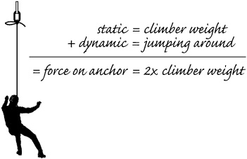
Forces from a hanging climber.
This discussion reinforces another concept introduced in Chapter 10: the difference between secure and strong. Certainly a rappel anchor must be secure, because it is the sole connection between the descending climber and his religious views on the hereafter. It does not, however, need to be particularly strong, because the possible peak forces are somewhere south of 1.5 kN (337 lbf), something a loop of burly shoelace might hold. The lesson is to be very attentive to the security of the rappel anchors you build, making sure that knots are tied properly, that anchors won’t somehow release themselves, that carabiners are clipped as they should be, that the directions of applied forces are taken into account, and that locking carabiners are used where appropriate; the strength issue will probably take care of itself. In other words, rappel anchors don’t have to be bomb proof, they have to be goof proof.
In this example of belaying, the rope from the climber runs up to a carabiner and back down to someone holding it with a belay device; this setup is sometimes called top roping with a slingshot belay. The belayer sensibly keeps the rope slack free, so the climber can’t fall any distance before the rope goes tight. Forces are basically static. The force on the climber’s strand is simply the climber’s weight, which is 0.74 kN in this example. Because of friction on the rope through the top carabiner, the force felt by the belayer will be reduced to 60 to 70 percent of the force from the hanging climber, or about 0.50 kN. The actual ratio is highly variable in practice, depending on characteristics and history of the rope, diameter of the carabiner, angle of rope wrap, and so on—typically there will be a one-third reduction of force when the rope passes through a carabiner used as a pulley, as in this example. The anchor holding the carabiner must sustain both forces simultaneously, for a total of about 1.2 kN (275 lbf). If the climber jumps around and deliberately applies the maximum force of 1.5 kN, the peak force at the belay would be about 1 kN, and the peak force at the top anchor would be the sum, 2.5 kN (560 lbf).
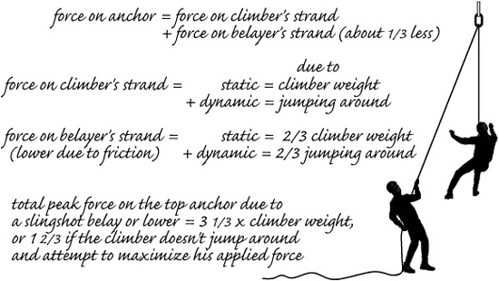
Forces from a climber hanging on belay.
There are some interesting points here. Our force analysis always focuses on the critical topmost anchor—if it fails, the entire safety system fails. The top anchor must hold a force that’s more than the weight of the hanging climber, but not twice that weight. If a frictionless pulley were used instead of a carabiner, the force on both strands would be equal, so friction actually reduces the force on the top carabiner as well as at the belay. Friction makes it possible for a lighter person to hold a heavier climber on a rope passed through at least one carabiner.
The purpose of constructing a pulley system is to decrease the force that a person pulling on a load must exert to move the load. Typically, the load is either a climber who has fallen and is hanging on the rope or is a bag of supplies known affectionately as “the pig.” I’ll get into pulley systems in detail when I cover self-rescue in Chapter 25, but it’s common to read cautions that the anchors for pulley systems must be exceptionally strong because of the higher forces possible. In fact, the opposite is true. The pulley system actually reduces the forces on pulley anchors and distributes the total force of pulling up the climber, or pig, over all the anchors and the puller. For example, in a pulley system having a 3:1 mechanical advantage, the puller feels one third and the anchors feel only two thirds of the load.
The forces I’ve been describing are basically static, but the main purpose of the roped safety system is to prevent injury to climbers in the event of a fall, when forces will be dynamic, and peak forces will be much higher than static forces. There are two approaches to examining exactly how much higher peak forces could be: start at the climber end of the rope, or start at the belayer end. The usual approach is to start at the climber end, but that leads to paranoia and is a poor guide to reality. I’ll start at the belayer end.
A falling climber could generate some pretty high forces; the purpose of the roped safety system and the belay is to bring the falling climber to a stop slowly enough that the peak forces don’t rise to the point that they break the safety system or injure the climber. In the bad old days, when ropes had little energy-absorbing capability, it was incumbent upon the belayer to execute a dynamic (slipping) belay as the principal energyabsorbing component of the safety system. The hip belay was developed for this, but it works only if the belayer wears gloves to reduce friction burns to his hands and to avoid complete loss of control of the rope as it slips around him, converting motional energy to heat. Belay brakes and energy-absorbing ropes came along that made for big improvements.
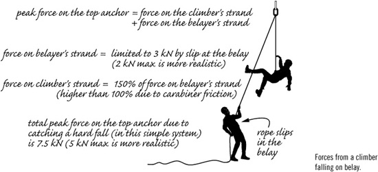
Forces from a climber falling on belay.
The belay brake (belay/rappel device) acts as a force multiplier, increasing the belayer’s holding power, static and dynamic. Static holding power depends on grip strength, posture, fatigue, rope diameter, and other things; it varies widely. Figure 0.18 kN (40 lbf) for one strong hand for about 1 second or 0.1 kN (25 lbf) for half a minute. This force is important when lowering another climber or yourself, but not in catching a fall. The force on the rope caused by a falling climber comes on suddenly, so you might expect that it would be difficult to establish a strong grip quickly enough; you’d be correct. It turns out, however, that you don’t have to.
The highest force that a falling climber generates occurs only for a fraction of a second, when the peak force at the belay also occurs. The belay peak force arises as the rope accelerates the belayer’s hand, arm, and part of his upper body, jerking them toward the belay brake. This force ranges from 0.15 to 0.3 kN (about 33 to 67 lbf); it can be reduced by about 15 percent if the belay setup allows the belayer’s entire body to be pulled or lifted, but that benefit is limited to around 3 feet (1 m) of motion even in the hardest fall—something you’d want to build into the belay setup whenever possible. Forces throughout the safety system subside to static levels in about a second. If the peak force would rise higher than the belayer and force multiplication designed into the belay brake can hold, rope will slip through the belay brake until energy is dissipated and the force on the rope diminishes. The belay basically acts to spread the fall energy over time and limit the maximum, peak force on the rope at the belay.
A static belay is one without any rope slip, as if the rope were tied off; a dynamic belay allows rope to slip while absorbing energy and limiting forces. All actual belays are dynamic to some degree, even with a GriGri. But is that a good thing or bad? In fact, what’s the basic purpose of a belay? This is an important point that climbers need to get their heads around, but it isn’t one that’s brought out in other texts, including The Classic.
As in the previous example of top roping forces, the force on the topmost anchor is the sum of the forces on the climber’s strand of rope and the belayer’s strand. In other words, the safety system component that receives (and must withstand) the highest force during a fall is the topmost anchor. The purpose of the belay is to keep the force on the topmost anchor as low as possible.
Static belays maximize forces throughout the safety system while dynamic belays reduce them, but if the belay is too dynamic, the climber will fall farther than necessary. The goal, then, is to produce a belay that’s sufficiently dynamic to keep the force on the topmost anchor comfortably below failure; there are many ways to do that. If the topmost anchor can’t possibly fail, the goal becomes making the belay sufficiently dynamic that the force on the climber isn’t too severe as she’s brought to a halt. Accomplishing these goals is highly contextual; the strength of anchors depends on many factors, including the medium in which they are placed (rock, ice, or snow). The distance a climber could fall safely depends on the terrain. The force conveyed to the climber (and anchors) as she’s brought to a stop depends on the energy-absorbing characteristics of the rope and other energy-absorbing components of the safety system. The ideal belay will always be a guess and a compromise; knowing the principles is the place to start. The guiding focus in trad climbing and mountaineering is reducing the peak force on the topmost anchor.
The hip belay, when used with a modern climbing rope, can hold a maximum force on the rope of about 1 kN without considerable slipping; that’s not enough for belaying a leader, so we’ll leave it out of the discussion. Belay brakes (belay/rappel devices) have been designed for compromise between rope slip and rope hold when used by a typical belayer on one strand of rope, and also when used by a typical rappeller on two strands of rope. Older designs were intended for fatter ropes; newer models accommodate modern, thinner ropes, sometimes by offering asymmetrical braking features that give a choice of holding power. Adding an additional carabiner to tube and plate brakes increases their force multiplication by about 40 percent. Still, all brakes hold the rope only up to some force limit without slipping. For old-fashioned brakes used with modern ropes, that maximum force on the rope and belayer is about 2 kN (450 lbf). Modern devices increase that to as much as 2.5 kN. The least intrinsically dynamic brake in common use is the Münter hitch, which slips around 3.5 kN in its stronger orientation and around 2.5 kN in its weaker orientation. Figures are for single ropes and depend somewhat on rope diameter and other factors.
If we take these figures and consider friction through the topmost carabiner, the strand of rope holding the climber will be limited to a maximum force 1.5 times greater, or about 3 to 5.25 kN. That’s the peak force on the climber irrespective of any force reduction by rope stretch. The top anchor will be subject to at most 5.5 to 8.5 kN peak force during any possible fall in this simple system. Those figures are probably less than you expected.
Is this good or bad? Is it the whole story? If it were the whole story, it would be good, and you’d already know more about safety system forces than the majority of climbers, but there are other factors that could substantially increase or decrease these forces.
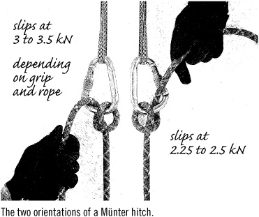
The two orientations of a Münter hitch.
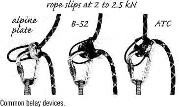
Common belay devices.
The UIAA long ago established an upper limit of 12 kN (2,700 lbf) for the force an energy-absorbing rope could transmit to a fallen climber; they figure that’s the maximum force a climber’s body could endure without fatality. This number comes from old studies of Scandinavian military parachutists, but when a parachutist pulls the rip cord he’s had time to get into a favorable position that, along with his specialized harness, lessens the consequences of impact caused by the chute opening. Falling climbers don’t have these luxuries and wouldn’t know what to do if they did. Nevertheless, for want of a better number, 12 kN is it. That’s more than twice the number we just figured, so what’s up? A couple of things. The 12 kN is a test number, whereas our figure is more practical. More importantly, the 12 kN would occur only in the worst-case fall, one in which the topmost anchor fell out or never was placed, the falling climber went past the belay before hitting the end of the rope, and the rope was tied off, not belayed.
The highest possible fall factor is usually said to be 2, but it could be higher if a substantial part of the climber’s tether is made of materials that don’t absorb energy, such as a long Dyneema sling or daisy chain. A factor 2 fall results when the climber falls from directly above a solid anchor to which the rope is tied. In such a fall, the climber (and anchor) would feel a peak force equal to the impact force rating of the rope (typically 8 to 10 kN), plus or minus some details.
Let’s take a look at the force on an example climber using a typical climbing rope. If the climber falls from 4 m (13 feet) above the anchor where the rope is tied for a total fall distance of 8 m (26 feet) on a 4 m length of rope—a factor 2 fall—the peak force felt will be around 10 kN. The rope would stretch about 35 percent (1.4 m or 4.5 feet) while delivering that force. Rope stretch is not figured into fall factor calculations. If the same climber took a 16 m fall on 8 m of rope (same fall factor of 2), the peak force and rope stretch percentage would be the same.
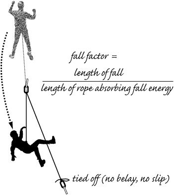
Fall factor.
A force of 10 kN would reflect a shattering fall, probably enough to injure the climber or end the day, but in a realistic factor 2 fall the fallen climber wouldn’t experience anywhere near that force. Why not? Because the rope wouldn’t be tied off, it would be belayed, and the belay would slip. The belayer might get rope burns and might release the rope, but even a Münter hitch could only apply 2.5 kN to the belayer’s rope and to the climber. Rope will slip at the belay until enough energy was absorbed to drop the force on the rope below the 2 kN applied by a typical belay brake. This is the basis of the energy absorbers designed for via ferrata, climbing routes on fixed iron rungs that, for protection, use a nearby cable with periodic anchors. Rope slippage is proportional to the fall distance: a whopping 10 feet would be added to our example 26-foot fall. Providing the climber didn’t hit anything on the way down, this factor 2 fall would result in only mild forces on the climber and belayer’s anchor (2 kN); not much more than a hanging climber could create by jumping around on the rope. This example should convince you, however, to wear gloves when belaying.
So a real-world, belayed factor 2 fall puts only 2 kN on the fallen climber and the belay. I’ll bet you find that surprising; it’s certainly not what you’ll read elsewhere. What will surprise you even more (unless you’re a physicist) is that the amount of force and rope slip at the belay is independent of the rope characteristics; they’ll be the same for a stretchy half rope used as a single, a typical 10.5 mm single rope, or a static rope.
Let’s take another example, this time a factor 1 fall, where the distance of the fall is equal to the length of energy-absorbing rope. If the climber ascends 4 m, places an anchor, climbs up another 4 m, and then falls (8 m, 26 feet), the maximum force on the example climber would be about 3 kN (675 lbf), and the force on the top anchor would be 5 kN (1,125 lbf), because, again, the belay would allow the rope to slip (about 6.5 feet, 2 m) at a force at the belay of 2 kN. Using a static rope would result in about the same forces, but more slip (10 feet, 3 m).
If you’ve been schooled by tradition, you’re wondering, “What the heck is going on here? This isn’t what I’ve been led to believe! How come a factor 1 fall hits the climber harder than a factor 2 fall? How come a static rope results in the same forces as a wimpy half rope? How come the forces are so low?” The simple answer is that the rope isn’t the only component of the safety system that lowers peak forces. The belay plays a big part, and that’s by design.
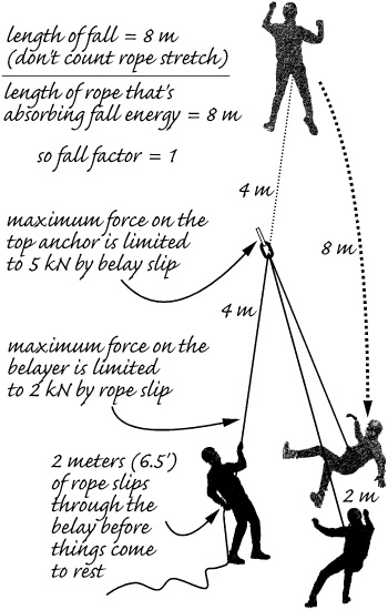
Fall factor example: a factor 1, tied-off fall.
In typical climbing situations the fall factor is often 0.3 or less, lower yet on sport climbs. During an 8 m fall of factor 0.3, the force on the falling climber will hit a peak of 3 kN (675 lbf), the belay would feel 2 kN, and the top anchor 5 kN, same as before, but the belay would slip only 3 feet. That’s with a typical 10.5 mm single rope; a half rope used as a single would result in slightly lower forces and no rope slip. An 8 m factor 0.2 fall on a 10.5 mm rope will result in the same forces, but no rope slip at the belay. A static rope would result in the same forces, but twice as much rope slip.
To summarize, during high-factor falls, energy absorption at the belay (due mostly to rope slip, which can be considerable) soaks up most of the fall energy and keeps forces low; at fall factors around 0.2 (depending on the rope), the belay doesn’t slip, and the rope’s energy absorption keeps forces even lower. This is probably surprising to you, but there’s more to the story.
The previous computations assumed that the climber is an iron weight tied directly to the rope. A real climber is a flexible object attached to the rope by a conforming harness; distortion of the falling climber’s body will reduce forces about 5 percent, and harness distortion will absorb another 5 percent in typical falls. Even the tightening of knots under load will absorb some of the fall energy, maybe 3 percent. Lifting of the belayer’s body may also reduce peak forces by a significant amount, maybe 10 to as much as 20 percent, if design of the belay system permits (this is the only influence that can be controlled by climbers). The overall consequence is that fall forces for short falls are less than those calculated, because of all these various factors that absorb energy and reduce peak forces. How much less depends on many things, even the climbers’ positions and postures, but the falling climber would more likely be shaken, not disturbed, in a fairly short though high-factor fall. The belayer, too, would be shaken, but hopefully wouldn’t release the rope or be pulled into an unsafe position. A fall that occurs after several anchors have been placed may see peak forces at the belay reduced further as anchor carabiners and runners are jerked into alignment by the tightening rope. On the other hand, carabiners and runners have no energy-absorbing stretch, even though they may contribute to the lengths of falls.
It may seem curious to name a product for what it prevents instead of what it promises to deliver, but that’s what Yates did with Screamers. These are conventionally sewn runners that are folded and sewn again in such a way that the secondary stitching rips when the applied force exceeds a certain level, typically 2 to 2.5 kN (450 to 560 lbf). In ripping, the Screamer absorbs energy and limits the peak force until all the secondary stitches are gone. Screamers and their several competitors are intended to be used at questionable intermediate anchors, not at the waist of the leader or at the belay; they limit the force on the placement, not the climber. The ripping point is just above the sum of the peak force from a thrashing climber, 1.5 kN, plus that from the belayer, 0.5 kN, so they rip only in some kind of actual fall, not from hanging or thrashing on the rope.
There are comparable gadgets that have been developed for safety on via ferrata, where climbers are typically attached to an anchored vertical cable, and fall factors much higher than 2 are possible. These devices, which can replace Screamers, are typically based on a short length of rope that slips under control of friction; they can be reused if the rope in them is rethreaded, whereas ripping runners can’t be rejuvenated. In the process of ripping or slipping, force limiters absorb energy and reduce peak forces, typically by about 15 to 20 percent.
The previously discussed influences help explain why sport climbing falls are not as severe as you’d expect (and why the sport is popular). Sport climbing anchors are placed close together and in optimal locations; this means that fall factors are low after only a couple of anchor clips, and the rope usually runs reasonably straight. Things are very different for trad climbers and mountaineers, who may choose or be forced to place widely spaced intermediate anchors on wandering routes.
Not if you’re the leader, he isn’t. It’s not uncommon for the trad leader to be out of sight of the belayer almost as soon as she leaves the belay stance; wandering and increasing friction on the rope continues from there. The friction of the rope around intermediate anchor carabiners, plus any friction against rock over which the rope runs, reduces the effective length of rope that’s absorbing fall energy, increasing the effective fall factor. When there are several anchors along the lead rope, even in a reasonably straight alignment, the effective fall factor can be double that calculated simply by the length of rope from the belay to the falling leader. If the rope also runs, even slightly, against rock in between those intermediate anchors, the effective fall factor can reach three times the one calculated, increasing the force felt by the climber and top anchor by 75 percent. Sharp bending of the rope at intermediate anchors or over rock makes things much worse. It can readily happen that only the rope from the climber to the next-to-last intermediate anchor is absorbing energy and reducing peak forces. A consequence of so much friction on the climbing rope is that the alpine leader can sometimes take a fall without the belayer even realizing it. Friction can mean there’s little energy-absorbing slip at the belay, which essentially becomes static. That is not a good thing.
Every such situation is different, but the general rules for avoiding increased forces are to use long runners to keep the rope as straight as possible, avoid having the rope running against rock and around corners, and place pro more frequently at the beginning of a pitch and farther apart at the end. These principles can restrict the feasible length of wandering mountaineering pitches.
Few climbers fully appreciate the factor-increasing phenomena; they just hate leading when there’s significant rope drag. It underscores the recommendation that choosing a rope having a low impact force rating is important for mountaineers—they may often find themselves relying on short sections of rope to absorb energy and reduce peak forces on themselves and their anchors.
The highlights of the preceding discussion include the following:
![]() Forces caused by a fall are likely to be lower than expected, especially at the belay.
Forces caused by a fall are likely to be lower than expected, especially at the belay.
![]() Forces are likely to be highest at unexpected points, particularly at the topmost anchor.
Forces are likely to be highest at unexpected points, particularly at the topmost anchor.
![]() Slip at the belay is what limits forces during harder falls; the rope has little effect.
Slip at the belay is what limits forces during harder falls; the rope has little effect.
![]() Rope characteristics limit forces (by stretching) during easy falls.
Rope characteristics limit forces (by stretching) during easy falls.
![]() Forces on critical elements of the safety system (the fallen climber and the topmost anchor) are significantly increased by rope friction at anchors and against rock.
Forces on critical elements of the safety system (the fallen climber and the topmost anchor) are significantly increased by rope friction at anchors and against rock.
Let’s take a look at the strength of individual components of rock, snow, and ice climbing safety systems.
International strength standards for climbing harnesses require them to sustain a force of 15 kN (3,380 lbf). The details of this specification are a bit nebulous, but suffice it to say that the harness is stronger than the climber. There are plenty of knots sufficiently strong to connect the rope to the climbers’ harnesses; none will fail to hold 15 kN. The belay loop, if your harness has one, is at least as strong. Your main HMS carabiner will probably be 25 percent stronger than the standard’s minima, or about 25 kN along the main axis and 9 kN cross-loaded or with the gate open.
All carabiners sold today will be adequately strong. Notice the pictograms on the spine. There’s a double-headed arrow pointing lengthwise and an adjacent number indicating the rated strength along the major axis when the gate is closed as normal. The UIAA/EN 362/EN 12275 minimum standard is 20 kN (4,500 lbf). Oval carabiners are allowed to pass with 18 kN, but few weasel. A double-headed arrow pointing across the carabiner indicates the strength when the biner is cross-loaded between its spine and gate; the minimum for this test is 7 kN (about 1,500 lbf). The remaining symbol is supposed to suggest a carabiner with the gate open; the minimum strength is also 7 kN, tested along the major axis. Ovals can skate by with lower numbers on this test, too. These strength numbers are based on single tests of new carabiners; manufacturers usually proof test each carabiner to half the closed gate strength, leaving telltale divots when they do. Contrary to old-school wisdom, carabiners do not lose strength when they are dropped (even off Yosemite’s El Cap) or abused, unless they are visibly severely damaged. Mangled carabiners or any that have been loaded near their limits, which happens very rarely in climbing, should be destroyed.
The strongest rock protection is undoubtedly a sling around a tree or permanent rock feature. Many fourth-class and parts of fifth-class climbs can be protected using runners, without hardware other than carabiners, and mountaineers endeavor to do so whenever possible (which is whenever they have enough long slings). Natural anchors should be good for the strength of the runner, ranging from over 20 kN for sewn slings to around 9 kN for a tied loop of 5 mm accessory cord.
Manufacturers of climbing hardware protection are required to quote strength ratings; these ratings include the strength of the main device, any associated runners or cable crimps, and the device’s holding power in rock—which depends on the quality of both the stone and the placement. Hmmm. Anyhow, strength ratings given for medium to large chocks, passive cams, and active cams are usually in the range of 10 to as high as 20 kN (2,250 to 4,500 lbf). Pro that fits cracks smaller than around 10 mm (½ inch) has lower strength ratings, and the really tiny ones may be rated at only 2 kN and are only for holding body weight when aid climbing, not holding falls. All such strength ratings are somewhat hypothetical in that they assume a solid placement, good rock, and the testing force applied in the most favorable direction.
Connecting a runner to a chock without using a carabiner.
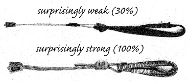
If you’re running out of carabiners, the question is sometimes raised as to whether a runner could be connected directly to the runner that’s permanently connected to the chock (commonly a wire cable), without using a carabiner. Definitely don’t use a lark’s foot (aka girth hitch) to connect a sling directly to a wire cable, but it turns out that passing a webbing runner through a cable loop and clipping the ends (so there are four strands supporting the load) results in surprisingly little loss of strength. If you tie your own chock runners with Tech Cord, as I recommend for the middle sizes, the loss of strength of another runner connected without a carabiner is insignificant.
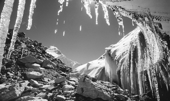
Just as rock has natural protection, so does ice. If you throw a sling around a substantial icicle, be sure that its base is well formed into a big, solid ice flow. Absent the good fortune to find a handy icicle, the other natural pro options are ice bollards and the Abalakov V-thread. Ice bollards should be as strong as the equivalent diameter of icicle in the same quality of ice, but bollards are intended only as rappel anchors, so a kilonewton or so is all the strength required. Making them secure lies in the craft of the ice sculptor, and security is the real issue. Security comes mainly from undercutting the rear edges of the bollard and ensuring that the rope will not pull from an untoward direction. Be diligent and expect to invest some time chipping away; in fact, unless you have no other option or unless a natural feature of the ice contributes, crafting ice bollards takes an inordinate amount of time.
The Abalakov V-thread is one of those elements of climbing that, like the European Death Knot, leaves you incredulous when you first encounter it, yet it’s potentially stronger than a more reassuring ice screw. This natural ice anchor is made by drilling two intersecting holes in solid ice using a long ice screw, after clearing away any rotten ice on the surface. You want the angle between the holes to be 60°. If you have two screws, leave the first one partly sticking out as a visual reference for targeting the second hole; after the second hole is started you can remove the first screw and peer down its hole in hopes of seeing the second screw appear. Five, six, or seven millimeter cord or 9/16-inch webbing is threaded through the V-shaped channel by teasing it down one side and snagging it with a wire hook poked in from the other; use wire in your ten essentials or a coat hanger you brought for the purpose. Cord is easier to work than webbing. Tie the ends of the cord or webbing into a loop with a double fisherman’s knot. The holes don’t need to be angled down or up, and they might better be drilled in a vertical pattern, one above the other, depending on how the ice looks (in a little gully, for example; remember that the weight of ice causes it to favor horizontal fractures). As with ice screws, place v-threads in recesses rather than on bulges. V-threads are more secure than ice bollards and take less time to establish, but they require a long (17 or 22 cm) ice screw; long ice screws are not the most useful. V-threads are less prone to melting out than screws. Popular ice climbing areas become festooned with V-threads by mid-season, and by summer the rock is strewn with abandoned cord loops—a chance for gear scavengers to clean up the environment. V-threads are used as rappel anchors or for belaying the second, meaning a worst-case force around 1.5 kN (340 lbf). There’s no way to determine the actual strength of a given V-thread placement, but figure 5 kN if the quality of the ice and your handicraft inspire confidence and the distance between the holes is at least 4 inches (10 cm). You’ll get double that strength if you can drill intersecting holes twice as far apart. V-threads in good ice have been tested to nearly 20 kN, so their use as a leader belay anchor (Anchor #1) is certainly conceivable and potentially better than a screw; I’ve never seen this actually done. I’m unaware of any tests of V-threads in hard alpine ice (in contrast to water ice), but I suspect they would work as well as comparably sized bollards, which means well enough for rappel anchors on the slopes involved.
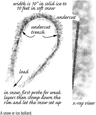
A snow or ice bollard.
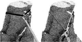
Ice screws and ice hooks are the only popular hardware alternatives from among many that have been experimented with since curved-pick ice axes made climbing near vertical water ice feasible. Ice hooks are somewhat specialized, highly variable in their placements (which tend to be in rock or frozen dirt as much as ice), must be hammered in and chopped out, and are only infrequently relied upon by mountaineers, so I’ll stick to ice screws. Modern tubular ice screws have polished, well-spaced, high-relief threads. Tests have shown that these threads, when the screw is placed in “good” ice, are more effective at anchoring the screw than the picket effect of the screw body. In good ice, the screw should be angled about 15° toward the direction of the expected pull, for maximum holding power. This is contrary to old-school advice to angle the screw away from the direction of pull. When properly placed in really good ice, an ice screw can hold over 20 kN. That’s the good news. The bad news is that ice is a highly variable medium, and the variation from placement to placement even in good ice is quite wide and difficult to predict. If subjected to the same statistically based specification as other pro, an ice screw nominally rated at 10 kN might need to be rated at only 5 kN to account for the variability of the ice in which it’s placed. Longer screws are slightly stronger than shorter screws, but most strength comes from ice near the surface; if that ice is “bad” or fractured, a longer screw helps only a little, even though it reaches down into solid ice. That’s because the screw will bend and fail in the weak surface ice; weak surface choss must be removed to put the screw head in solid ice. This is particularly important on a glacier or at the base of a waterfall, where even the best ice may be aerated, and reaching anchor-grade ice may require considerable excavation. The screw alone is stronger, even if it can’t be placed fully into the ice, than if it’s tied off at the surface of the ice with a slip knot runner or the wire of a wired nut, unless the extended length exceeds 5 cm (2 inches)—which would be a scary-looking placement. In “not so good” ice, placing the screw perpendicular to the surface or angled 5 to 15° away from the direction of pull may be the strongest option, but not good ice is even more variable than good ice.
An Abalakov V-thread anchor with rap ring and backup runner ready to rappel.
What is “good” ice? Pretty much what you’d expect: ice that has formed slowly into solid flows from meltwater, not from frozen water spray or metamorphosed snow. Usually such ice will be on lower-angled surfaces and may even be transparent. Warm ice tends to be more plastic and to resist fracturing better than very cold ice, so screw placements are stronger. Bad ice, which all ice is to some degree, looks like white foam plastic and may have obvious air pockets. If cold, it’s brittle; if warm, the ice may turn to slush as you climb. If the screw is warmed by sunlight on its exposed features or by water running behind the ice, it will melt loose surprisingly quickly, making its threads useless. I can assure you that having water come running out of an ice screw as you place it is unwelcome for a number of reasons, not the least of which is your sudden awareness that it may fall out even before you can clip it, yet you have limited options and limited time to explore them. Think of a good ice screw placement as having a strength of about 10 kN, a mediocre placement as having a strength of 5 kN, and an exceptionally good placement as having a strength of 15 kN in the real world. Learn to clip ice screws with your fingers crossed.
When placing multiple, equalized screws in ice flows, my dictum of placing anchors more or less vertically in line with the applied force (as opposed to side by side as most texts illustrate) becomes even more important than on rock. This is because ice tends to fracture horizontally due to internal stress caused by its weight; you don’t want to enhance this effect with your anchor sites. Place your ice screws as far apart as feasible, 2 feet at least, to prevent one screw from weakening the ice of its neighbor or the failure of one screw fracturing the ice where the other is placed. If you’re considering purchasing a couple of screws in hopes of coming across ice of good enough quality to place them, have a look at the Petzl/Charlet Laser Sonic. These have the expected integral crank for placement ease, but the handle end is a rotating bolt hanger; this allows you to remove and even place them with the runner or a keeper cord attached—no more dropped screws bounding down the gully below you, making chimes that sound like a cash register. Place them at your waist like any other screw, but you can be clipped in before you start cranking.
If you think ice protection is screwy, you’ll find that snow protection is a real crapshoot. In favorable snow, anchors can be amazingly strong, but in snow like you’d want to ski on or kick steps in, considerable skill and time will be required to construct worthy anchors. Same story if the snow is firm, but highly sun cupped. The exact nature of the snow may not be apparent, so you can seldom be certain of the results of your efforts. To make things worse—or better, if you’re lucky—snow is constantly changing, even minute by minute. Here are some guidelines to help you understand the potential strength of snow anchors and how to make the most of them.
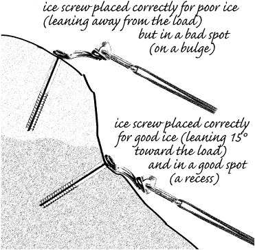
Ice screws in good and bad ice.
In soft snow, a strong snow bollard must be huge, maybe 10 feet across—requiring at least 40 feet of rope and excavating a lot of snow. If the snow is that soft, there’s little reason for an anchor because climbing is secure enough without a belay, especially on a slope of low enough angle that stumbling around and constructing a big bollard is feasible. A large bollard in heavy, well-consolidated snow can be very strong, maybe up to 10 kN, but success is hard to predict; a sound snow bollard looks exactly like one that will allow the rope to slice through a weak layer in the snow. Snow bollards are used mostly as descending anchors on lower-angled terrain, so they need withstand only about 0.5 kN.
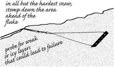
The aim of a snow bollard is to contact a sufficiently large surface area (length) of rope against a sufficiently large amount of sufficiently firm snow. Snow that has been worked (stomped) tends to harden after several minutes; damp snow can turn very solid, as you see with the snow left by plows. Usually, building a snow bollard in old snow in a shaded area beats building one on nearby sunny snow. You’ll want to stomp down the snow around the bollard periphery, on the inside of the bollard’s rope channel; the snow outside the rope or the depth of the bollard’s ditch doesn’t affect strength. Start the stomping process as you define the bollard’s teardrop shape, and evaluate the snow’s hardening as you refine the undercut. If the snow is too firm to work with your feet, you’re in luck—a smaller bollard, maybe only a few feet across, is justified; just make sure that it isn’t only the surface that’s firm.
If you imagine yourself constructing a bollard on steep snow in order to descend a steeper section immediately below, consider this: one of the most common starting points for avalanches is a “pillow” of snow—a convex bulge. In other words, the very spot where you’re about to dig a big trench through the surface layer of snow that may be under tension and ready to release. If a ski cut could cause a release, cutting a big slot and tromping around while doing so seems foolhardy. If you do manage to slice off the bollard with the rope, you’re in double trouble because it’ll join you for the ride down.
What about a hip belay? After all, we’re not talking about a super steep slope or hard falls on snow. Wouldn’t the inherent weakness of a hip belay be turned from a liability into an asset when belaying on snow? The answer is yes. If you want a weak, dynamic belay, a body belay on snow might be just the ticket. A hip belay can be expected to hold a kilonewton at most, and the rope will slip even then; it will slip more if the rope is snow covered, and the belayer is wearing insulated gloves. Holding the rope will be the limiting element if the belayer digs a deep U-shaped channel to sit in and is well braced, basically becoming a cogent deadman anchor with a frozen butt. Adding additional backup protection is probably pointless, for if it were actually secure, hardware protection would be a better choice for the belay anchor than a belayer’s body. Running the rope through a carabiner at your waist will increase your holding power and decrease the tendency for the taut rope to twist you around, though it isn’t likely that a hip belay will be called upon for power.
There are many situations in which a mountaineering party might need a weak belay when climbing or descending steep or icy snow. Hard core types might do without, but a typical party will be far safer to expend the additional time to establish anchored belays. That means knowing how to set them up efficiently and what results to expect. Old-school texts often don’t get it right.
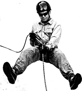
Boot-Ax Belay. In every mountaineering text you’ll see an illustration of the classic boot-ax belay. Invariably the illustration incorrectly shows the hands reversed from the strongest position, even in The Classic; either leg can be uphill but the hand position is critical to getting the maximum wrap of rope around the boot. Strength is not the boot-ax belay’s forte, but you might as well get all that’s available. In strong snow, when it’ll be difficult to force the ax shaft all the way down (but do it anyway), a proper boot-ax belay without crampons can hold 2 kN (450 lbf), maybe a bit more if the belayer has a high tolerance for pain. In softer snow, holding power will be significantly less, even when wearing crampons and even after stomping down the area around the placement and giving the snow time to set up. Hopefully, soft snow will also result in gentle falls, or none, because any belay using an ax is likely to whack the belayer when it pulls out. One problem with this belay is the difficulty of safely taking in rope; fancy flailing in an awkward position is needed. Nevertheless, the weakness of the belay (keep in mind it’s the topmost anchor) makes it imperative to take up rope quickly and minimize slack to the climber. The boot-ax belay is more efficient handling descenders than climbers and is best used to guard against short slips turning into long slides.
Sitting hip belay on snow with both strands of rope through a single carabiner at the waist.
The Stomper. Another classic, weak belay that’s frequently illustrated in a suboptimal orientation is the boot-carabiner-ax belay. Note that the belaying carabiner’s runner should go through the hole in the ax head or, unless it’s otherwise tethered, the ax may be lost if the belay fails. Like any other hip belay, even when correctly executed, the stomper belay is limited to holding little more than a kilonewton, depending on the belayer’s grip strength and pain threshold; it’s for slips on slopes, not falls on ropes. The boot-carabiner-ax business doesn’t add significant brake action; it merely redirects the rope. The force on the carabiner will be approximately equal to the sum of the force on the rope from the fallen climber plus the force being held by the belayer, or roughly 150 percent of the force the falling climber applies. A Münter hitch belay would make better use of any strength a snow placement provides—that would be the new-school approach. Using a Münter hitch on a boot-carabiner-ax belay for ascenders is a pain in the back, because you’ll have to bend over and use both hands to take in rope. It works great, however, for descending mountaineers and is easier on backs than the boot-ax belay, ascending or descending.
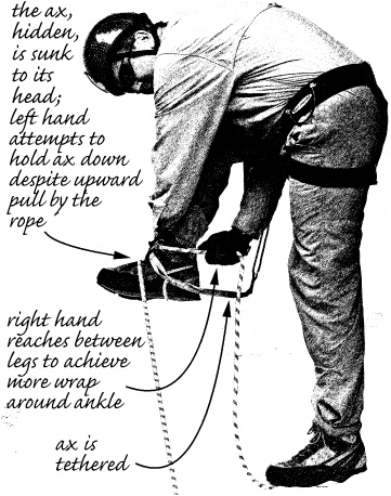
The boot-ax belay.
Torn between the boot-ax belay and the stomper? Go with the latter. Rope management is easier, it’s less directional, it allows the belayer a better view of what’s being belayed, it’s less likely to cause injury by the flying ax should the belay fail, it causes less pain on the belayer, and it’s slightly more robust. Both belays are best used for the second or descenders, not for belaying leaders who could take significant falls.
Laying It on the Line. What about a self-arrest on snow—how strong could that be? This is of certain interest because a self-arrest might be the anchor that stops another climber who’s fallen, particularly into a crevasse—a potentially serious fall, even though the fall factor cannot exceed 1. A well-executed self-arrest in good, horizontal snow can momentarily withstand 2 or 3 kN once solidly established; the limiting factor is the ability of the arrester to briefly endure the pain of holding the force on his harness, reminiscent of medieval torture methods. If you consider the length of rope between glacier hikers, the likely fall distance, and the force reduction by snow (especially if knots are tied in the rope), you arrive at a maximum force on the falling climber of around 2 kN—pretty close to the strength of a single self-arrest. The key to traveling safely on crevassed glaciers and keeping fall forces manageable is to keep the rope linking travelers as tight as practical and for the belayer(s) to attentively go into self-arrest as quickly as possible upon a fall. If the party is inattentive, delays arrests, and allows excessive slack in the rope (or carries coils!), fall forces could exceed the ability of self-arrests to hold, allowing what might have been only an individual’s slip to turn into a party’s desperate tumble toward the abyss.
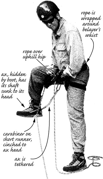
The stomper belay.
Hardware anchors for snow are of two kinds: pickets and deadmen. A picket is an aluminum stake with a T-shaped cross section intended to be driven into harder snow or softer ice. They are available in 2-foot and 3-foot lengths, but the 3-foot versions are just evidence of desperation (understandable, if you’re seeking strong anchors in soft snow) and take longer to place; there’s little strength to be gained from the 3-foot versions. The strength of a picket depends on the quality of the snow or alpine ice into which it’s driven, mainly the surface strength. Whack them in as far as you can, angled about 15° away from the likely direction of pull, and attach the connecting carabiner or runner at or only slightly below the surface; attaching the load higher substantially weakens the placement, and attaching it lower creates an upward force unless the runner is entrenched. You’ll have a reasonably capable anchor, one that could even be used for a leader belay anchor or intermediate climbing protection. When the snow is soft, stomp it thoroughly in front of the picket; it’s the strength of the snow or ice at the surface that limits the strength of driven pickets. A picket that’s had an end exposed to the sun for a time may only be resting, not anchoring; you may be able to slide it up and out with your fingertips. Place pickets with their heads below the snow surface whenever possible and cover exposed metal with snow to prevent solar melt out; just be sure that a pull on the runner will not bring them up and out. Whacked well into glacier ice, pickets make appropriate rescue anchors, given the way rescue systems distribute loads. Some pickets have a stainless metal end covering to hold up against repeated pounding into firm snow or névé; if you’re planning a lot of this, bring along a hammer tool and spare your ax. In the end, the strength and security of a driven picket is more about the snow or ice than about the aluminum; you might figure on a placement strength of from 1 to 6 kN, depending. Hopefully that will be all you need, or hope you’ll be able to place two and combine their strengths.
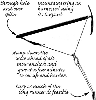
A mountaineering ax can be used as a driven or buried picket. You can even purchase pickets that appear to be headless axes. Axes are B- or T-rated according to several tests (see Chapter 15 for details on ax features). You’ll be using a B-rated ax having a shaft rated to hold 2.5 kN. That rating applies to the head resisting being ripped off. You can do better using the ax as a picket if the snow is firm and well stomped in front of the placement, and if you attach a runner through the hole in the ax head and stomp the shaft down until the ax head is at or just below the snow surface. Angle the shaft of the ax about 15° away from the direction of pull and hope for 3 to 4 kN, best case, because that’s all the ax itself can handle. With ideal alpine or glacier ice you could even use the pick of your ax as a driven picket and attach the load-connecting runner to the hole in the spike. If you’re holding a companion who’s fallen into a crevasse, this may be your only option; place your pick with conviction. If you’ve climbed vertical ice, you know that a remarkably short length of pick or crampon point can support body weight, so it shouldn’t be surprising that the entire pick sunk to the shaft would support substantially more if conditions are favorable, which would be unfavorable for attempts to deeply embed the shaft of the ax. Figure a couple of kilonewtons, maybe more unless the head pulls off, and figure on some effort digging out the pick if it doesn’t.
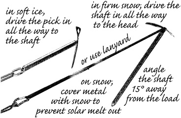
Mountaineering ax used as a picket.
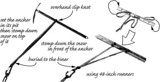
A deadman is any object buried in snow for use as an anchor. The trick is to cut a narrow slot for a straight and direct connection to the deadman, and then to drive or bury the deadman perpendicular to the slot and the direction of pull. A picket makes a great deadman, better than a horizontally buried ice ax shaft, but nowhere near as good as a buried ski. Nontraditional objects might serve in desperation, including a snowshoe, a lassoed backpack stuffed with snow, or even your partner’s sacked tent with poles; use slip knots to attach runners around the objects. After digging out the hole for the deadman, stomp snow around the buried object and allow a few minutes for the snow to set up before loading the anchor; soft snow will harden considerably after it’s been worked this way, and heavy wet snow may become ice hard. The resultant placement can be remarkably secure. In heavy summer snow I’ve called off the pulling test out of fear of damaging the shaft of my ax; an entire party of mountaineers was unable to pull out a ski buried under only a few inches of snow (attach the runner with a slip knot and be sure it won’t be cut by the ski edges). In the same conditions, an 8-foot wide snow bollard could be sliced out by the determined pulling of three people.
In good (heavy, damp, not too cold) snow, a picket deadman might hold 8 kN, close to metal failure. In cold, fluffy snow you might be lucky if your deadman holds 1 kN. This means a picket is stronger as a deadman that is connected at its center than as a driven picket that is connected at its end; theoretically it should be twice as strong. Using a carabiner to attach the runner to a picket isn’t the best way to achieve this strength; a webbing runner passed through two holes and over the ends better spreads out the load. Even cinching a runner directly through a single hole will be sufficient (not “girth hitched” around the picket, which tends to crush the picket as it tightens). Use one of those 4-foot runners I recommend; the longer the better. Always stomp down the snow well ahead of a deadman in hopes it will set up with improved strength, but your results will vary unpredictably. The snow-stomping business is critical to the strength of any deadman placement, and you always want to construct a burial pit that’s large enough for plenty of backfill with stomped-on snow; dig the pit from the load side, so your feet will be stomping snow as you dig. If you must attempt a deadman anchor in soft snow as part of a rescue, you’ll want to equalize together as many snow anchors as you can set up; I’ll cover complex anchors later, in Chapter 12.
Vertical Burial. A picket used as a deadman can be placed vertically, attached by a runner in the middle and entrenching the runner ahead of the picket. Horizontal placements are vulnerable to weak layers in the snowpack, so always probe the snow before you plan your burial. A vertical picket deadman is 20 percent or more stronger than a horizontally placed picket deadman. It’s certainly faster to place in firm snow, but be sure you don’t lose the opportunity to stomp the snow around the hardware to gain strength, as you’d always do when establishing a horizontal placement. In optimal conditions you might hit 9 kN before failure of the picket itself occurs, especially if you use my method of attaching the runner to distribute the force over the picket.
In order of increasing strength in the same snow we have: a picket driven completely into the snow, the same picket buried horizontally as a deadman, and for the greatest strength the same picket placed vertically as a center-connected deadman.
Horizontally buried pickets as deadmen.
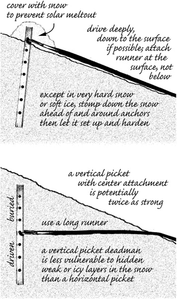
Picket as a vertical deadman.
An ice ax can also be buried as a deadman. Attach a runner to its middle using a slip knot. Failure of the shaft sets a strength limit around 4 kN, and you might get close to this in heavy, well-stomped and set-up snow. You get slightly more strength using the lanyard to hold both ends. In general, any deadman held by its ends is stronger than if held by its middle.
Snow flukes are deadmen made of bent sheet aluminum with cables that attempt to hold the plates at favorable angles, causing flukes to increase their burial depth when pulled on. I assume that a fair number of these things get sold, but in my personal experience they aren’t worth their weight on the pack. Standards call for a mechanical strength of 6 kN (1,350 lbf), which suggests that strength in snow will be less. I’ve had better luck with the flat versions with bent edges than those with a single bend in the middle, but neither inspired confidence. They either pulled out outright, or moved off to the side and pulled out, or dived down to a frozen layer and pulled out along it (be sure to probe for a hidden ice or weak layer before placing a snow fluke—especially important on a snow-covered glacier). There may be snow conditions where good security is possible, but pickets are more secure and much more versatile in my opinion. In a pinch, you could use your shovel blade or a snowshoe as a snow deadman by constructing a harness from that length of 6 mm cord you wisely carry; their large area makes for impressive holding power, especially if the snow in front is firm or well stomped.
Mountaineering ax used as a horizontal deadman.
Flukes’ weakness might be inevitable given their size. All things being equal, the holding power of any deadman is proportional to the area resisting the pull against the snow, so a picket deadman and a fluke with similar areas should be comparably strong. For example, a 2-foot-long by 2-inch-wide picket will have approximately the same area as a 6-inch by 8-inch fluke. All things are not equal, however, as the fluke’s cable holds it at an angle that reduces its effective area and strength. If the fluke works its way down to an ice layer, that angle can increase, and the fluke will hold even more poorly. Flukes should be buried as deeply as feasible, behind stomped-on and setup snow. In good, well-stomped snow their tested strength can be impressive, but just stuffing them down into snow is ineffectual. Never place multiple flukes in a line, as any movement of the first fluke through the snow will create a weakness that will make the following flukes much less effective. Don’t use a fluke as part of a joined (“equalized”) anchor system if their typical movement could compromise other placements.
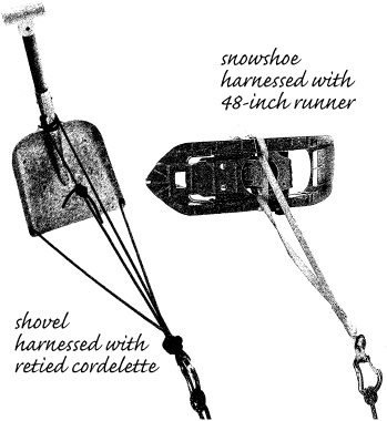
Improvised snow anchors.
Multiple snow anchors involve some subtleties that don’t arise on rock. Multiple, connected anchors are an effective approach to compensating for the variable and unpredictable nature of snow. The strength of a snow anchor placement depends not just on the snow in immediate contact with the hardware, but also on the snow that lies broadly in front of the anchor in the direction of the load. In old-school texts you see illustrations of anchors made with, for example, two perpendicular ice axes in contact. Such a placement is far weaker than placing the axes widely apart and connecting them with an equalizing runner—obvious once you realize that it’s the snow around the axes and not the axes themselves that limit strength. When snow at one ax fails, any ax close by will also fail. When setting up equalized anchors, it’s reasonable to assume that snow placements are equally strong if placed far enough apart so they act independently—that’s the new-school approach, where cordelettes come into play.
A correctly placed fluke.
Force multiplication; anchors above, loads below.
If worse comes to worst and your snow placement fails, expect that failure under load will be sudden. Not only will you no longer have an anchor, but you may be threatened by flying hardware with pointy ends. Flukes in poor snow fail progressively and may even travel some distance under the surface without losing what strength they have; the snow acts like a force limiter. If you notice that a vertical picket is being pulled toward its load, back off immediately because that’s an indication that the supporting snow has been compromised, and catastrophic failure is imminent.
The UIAA has taken care to specify the key hardware components of the safety system by requiring minimum strengths that will prevent any single element from being an obviously weak link. The security of anchor placements, not the strength of their hardware, is what determines their overall benefit to the roped safety system. The upshot is that the safety of climbers depends on their personal knowledge and skill in using and placing secure anchors—climbers’ fate rests in their own hands.
The safety goal of the skillful roped climber is to place secure anchors and minimize the forces on anchor placements, especially the topmost anchor. Unfortunately, there are a number of subtle ways that forces can be increased beyond what might be expected. These scenarios are referred to as force multiplication. Force multiplication can be categorized as lever effects or pulley effects.
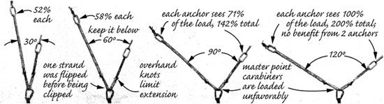
Force multiplication can arise when two anchors are thoughtlessly connected. If the angle formed by the runners connecting the anchors rises above 30°, the forces on the anchors increase above their expected share of the load. When the included angle reaches 120°, each anchor will experience a load equal to 100 percent of the applied force. In other words, at that angle and higher there’s no strength benefit in having two anchors—both anchors bear the full force, defeating “equalization.” Furthermore, the direction of the force is sideways instead of in the direction of the rope’s pull.
It’s unfortunate that many illustrations in climbing texts show anchors side by side, often with connecting runners at high angles. To avoid sneaky force multiplication, a proficient new-school climber is always searching for anchor placements that are essentially in line with the applied force, whether in rock, ice, or snow.
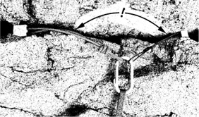
Another example is the construction of an anchor by looping a short runner around a rock feature.
The forces on the rope used in a Tyrolean traverse or on the webbing used in a slack line can be incredibly high. In order to avoid an initially wild ride down the first half of the rope and a major grunt hauling yourself up the remainder, the rope of a Tyrolean traverse needs to be as flat as possible. That means the rope must be tight, and that means a very high included angle at the point where the traversing climber is hanging, almost 180°. Tyrolean traverses should be avoided, and when set up just for fun, they should be made with beefy static line and really beefy anchors and backups.
Another example is a hand line set up to protect members of a mountaineering party as they traverse an exposed section of rock or steep snow during a climb—a technique often illustrated in mountaineering texts, including The Classic. The anchors at the ends of such a line must be exceptionally strong and secure, because lever-type force multiplication increases the tension on the line to greater than the force of a falling climber.
Lever-type force multiplication can also develop on protection that’s placed in opposition. Sometimes the exact angle is difficult to determine, but you can be sure that high forces can arise.
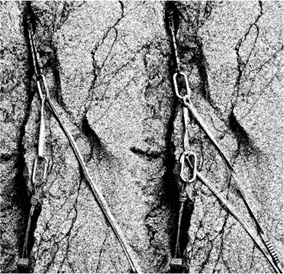
In addition to force multiplication caused by the high included angle of the chocks’ runners, the carabiner in this placement illustration is triaxially loaded, which significantly reduces its strength.
Force multiplication, reduced with a longer runner.
Sneaky force multiplication.
We’ve already encountered the most common example of pulley-type force multiplication, the upper carabiner in a belay system acting as a force-doubling pulley.
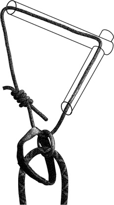
Another example arises when placing protection pieces in opposition. You might at first think this setup is clever: the lower chock protects against an upward pull and the upper placement resists a downward pull, and the two hold each other in place. Don’t be seduced. The force on the upper anchor will be twice that on the rope, twice what it would be if the upper anchor were used alone—force multiplication at work.
Pulley-effect force multiplication and a cure.
The problem is fixed by tying a clove hitch at the upper carabiner with both strands or at each carabiner with a single strand, as shown; your choice will depend on the consequences to the security of the placements when the anchor is loaded.
There are numerous other examples of where force multiplication arises in climbing and mountaineering. Some instances may be benign, others not. If you’re a physics geek you might be able to perform a vector analysis of what’s going on, but if you’re like most of us, you should just develop an informed intuition and rely on it. If a setup looks squirrely, it probably is.