‘DANCING IN ATTENDANCE’
Ishould like to suggest that you look at some photos of ships at anchor. Perhaps go onto www.navsource.org and look at images from the late nineteenth and first half of the twentieth centuries. Very often you will see the larger ships with smaller vessels and boats milling around.
These may be the ship’s own boats. Or they could be harbour craft of various types, oilers and colliers, victualing craft, barges and lighters, tugs, pilots’ launches or even private yachts in earlier times.
Each of these smaller craft has its own purpose vis-à-vis the larger one: transporting officers and men, loading fuel and supplies, off-loading junk and rubbish, pushing or pulling the ship. The ship’s own boats may be simply tied up to the boat booms, waiting to be used.
The depiction of this kind of scene is the purpose of what I consider to be the simplest of ship dioramas. I give it the generic title ‘Dancing in Attendance’. It may not be a complex idea, but this does not prevent it from being a remarkably effective form of diorama. In its most basic form it may not be big and brash enough to impress judges at a big competition, but that is not my intention. What I want to do is to put a model ship into context and bring it to life, and an arrangement where there is just one or two small boats having a purposeful relationship with the main vessel can do this superbly.
Look at the pictures on page 22 below. These show my model of the armoured cruiser HMS Kent and will illustrate this point.
The ship is at anchor. The port boat boom is rigged and two of the ship’s boats are moored to it. A steam launch is by the accommodation ladder hanging from the quarterdeck and a few people are fussing around at the top of the ladder.
This is the ‘dancing in attendance’ idea stripped down to its absolute fundamentals. It is so stripped down that it would turn no heads in the diorama classes of most large competitions. In fact, it has been entered in single ship classes. Nevertheless, as an example of a bit of animation being put into a model, it is my sincere opinion that it works very well indeed. Even though it was a number of years ago that I built this model, it remains one of my favourites.
Let’s examine what happens when we look at the model. The viewer’s eye is taken on a journey. It is first drawn to the steam launch and the accommodation ladder. It is as though we are entering the model by climbing the ladder, just as the officer has done. This area forms one of the main foci of interest. Attention can then move to the mainmast. With its intricate rigging, this is another major focus of interest. We then go along the main deck, past boats on the skid beams and davits, and the funnels with their guys. These are secondary foci of interest. We arrive at the bridge area. This is the second major focus. There is the foremast, again with rigging and the signal flags giving a touch of colour, and activity happening on the bridge. From the bridge, attention can go to the foredeck, or alternatively, via the men cleaning the 6-pounder gun, to the boat boom, and thence back to the steam launch.
A successful diorama will be telling a story to the viewer. This diorama is telling a story, but I don’t know what it is. Maybe you know better? The areas of main interest are where the viewer finds himself asking questions about what is going on in the model, and his imagination is then called into play in order to answer them. You look at the quarterdeck and say to yourself: ‘Who is that, coming on board?’, ‘Where has he come from?’, ‘Who is he going to see?’, ‘What news or orders has he brought?’, ‘Will they soon be sailing away?’ Or you will look at the flag signals and ask to whom they are directed and what they are saying. And I would have to reply, in all honesty, that I don’t know the answer to that one either. D-R-M are simply my father-in-law’s initials. As a signal it could mean anything from ‘Party tonight, bring your own booze’ to ‘The Bosun’s down with the measles!’

HMS Kent

HMS Kent. Bridge and foremast

HMS Kent. Steam launch at the quarterdeck

If this chapter is called ‘Dancing in Attendance’ then this diorama must be the Royal Ballet. This is Jim Baumann’s model of the French battleship Henri IV. Just look at all the pleasure craft and fishing boats swirling around. The whole thing bewitches the eye. Being a sailor, Jim has ensured that all the sails are set correctly for the direction that he has decided the wind is blowing. (PHOTO BY JIM BAUMANN)

I’m not sure what Jim has done with the lighting in this photo. Maybe he lowered the light levels deliberately or maybe not. But the effect is to make it look like one of those seventeenth century Dutch paintings with boats in a storm. You cannot deny that it is extremely atmospheric. (PHOTO BY JIM BAUMANN)
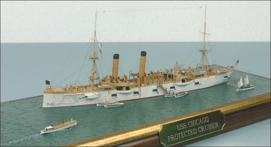
A vaguely similar idea, but not so well executed. This is my model of the USS Chicago with boats around her. Jim had often said he would like to have one of my models in his collection, so I hoisted his daughter’s initials in signal flags, and this one is now sitting in one of his display cabinets

This shows the overall layout. The Chicago is not on the centre line of the base and not parallel to the sides. Neither is it on the exact diagonal. It is positioned slightly towards the back of the base. This gives room in the water for the steam launch and the sailing boat not to feel crowded and have their own individual identities
Before I go any further into the construction of a particular diorama, I think this would be a good point to describe the processes involved in making your own base, as this is something that all dioramas are going to need.
If you are going to be picky about the size of base you want to have, it tends to follow that readymade bases are not going to be suitable. It is possible to get bases custom-made to your exact specifications, but it is actually not too difficult to make your own. I have always done so; I only rarely use commercial bases, and have never had one specially made.
My bases are made from MDF, usually 4mm thick, and they are surrounded with a frame cut from picture frame moulding, which I buy in 2.4 metre lengths, and I cut my own joints using a small mitre box.
I cut the moulding in an unusual and specific way. If you take a conventional picture frame and place it on the table face up, you will notice that the rebate that takes the glass, picture and backing is on the back, or rather the bottom as you are now looking at it. If you were to imagine the glass as the sea surface and the model is floating in it, then the frame ends up being raised above the sea. To my mind this makes the ship look as though it is floating in a swimming pool.
So what I do is to turn the moulding outwards by 90° so that the rebate is brought to the front inner edge of the frame. The sheet of MDF is now raised up so that the surface of the sea appears to be on top of the frame, and the ship is not so constrained.

I am making a base and case for my next project, HMS Agincourt in 1/700 scale. I wanted the size of the sea to be fourteen inches long by four inches wide. I think it’s easier to cut wood to fit exactly into and around an acrylic case, than it is to cut acrylic sheet, or order it, such that the resulting case will fit neatly. So I ordered 2mm thick acrylic first of all, and had it delivered ready cut to size, bearing in mind the need to have an allowance for the butt joints at the corners. You can see that I am assembling the case around a piece of cardboard of the appropriate size, to keep the ends from slipping too far inside, and the corners square. The bulldog clips are there to do the same at the top, being positioned exactly 2mm from the end of each side piece. The edges have been sanded smooth and polished where necessary so that they will glue well without the joints being too obtrusive. I have used a solvent cement called Evo-Plas Tensol 12, which is specifically intended for plastics like this, and obtained from the company that supplied the acrylic

Using the mitre box to cut 45° angles. The mitre box is clamped firmly to the worktop. The metal bookend from IKEA or a similar emporium is also clamped at an appropriate distance to act as a stop, so that I can cut pieces of moulding that are identical lengths. I am using a sharp dovetail saw. Incidentally, this one is a saw that cuts on the ‘pull’ stroke, in Japanese fashion, and I find it very good. I have posed this picture for the camera. If I were actually cutting, I would be holding the moulding in place with my left hand, and that would be all you could see. I’m sure I have a most elegant left hand, but it is hardly relevant to the book
Two points require to be made about this process. First, the moulding has to be chosen carefully so that it will still look attractive around the base when it is turned outwards like this. Secondly, you have to cut the mitres yourself, not get a picture framer to do it for you. Commercial framers use guillotines rather than saws, and if the moulding is put into the machine in what is regarded as the ‘wrong’ way it gets crushed instead of cut cleanly.
Before now I have just kept my models in a glass fronted cabinet to protect them from dust and damage. This protection is only partial; in particular static electrical build-up still attracts dust. So I have recently decided to include an integral acrylic case with my bases, and I shall show you how to do this too.
USS LANGLEY
I am going to illustrate the process of constructing a ‘Dancing in Attendance’ diorama with my model of the USS Langley, the US Navy’s first aircraft carrier. It uses the 1/700 resin kit from Loose Cannon, and is combined with the yard oiler and garbage lighter from Battlefleet Models and some dockyard barges that I scratchbuilt. You might say that the theme is one of ‘In One Side & Out The Other’, with the oiler representing the ‘in’ and the barges and garbage lighter the ‘out’. I know it’s a fairly tenuous thought, but feel free to take it or leave it.
I love the little harbour craft that are produced by Battlefleet. They may not be the most detailed or advanced kits on the market, but they are incredibly useful for the diorama builder. You only need to place one or two around a more major vessel, bearing in mind that the smaller vessels have to be doing something, and you are on your way to an instant diorama. Add some mooring ropes to show that the vessels have a definite relationship and some crew figures communicating with each other, and there you are. You can win a prize.

The acrylic case has had its top glued on and is now reasonably rigid. I measured the lengths of moulding directly from the case, so that the frame would fit snugly around it but still be easy to remove. A baseboard of MDF was cut to the same size as the cardboard in the first photo, and this has been glued into the rebate in the frame. You have now formed a slot into which the case will neatly fit
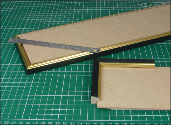
I may not have explained the reason for turning the moulding through 90° entirely clearly, so this photo should make the point. In the front I have cut the moulding in the normal orientation that you would use to frame a picture. The position of the rebate causes the frame to sit proud of the base, just like, as I said earlier, a swimming pool. At the rear is the base as I intended. Turning the moulding brings the rebate to the top and the base is now level with the top of the frame. You can see that there is no gap under the ruler. I really think this is a much superior way of going about it. It is just that you have to do it all yourself rather than paying a picture framer. If you don’t count the time spent building the acrylic case, it takes less than an hour to make a typical base, so it is not only cheaper than having it made for you, it is probably also quicker, unless you live over a framer’s shop!


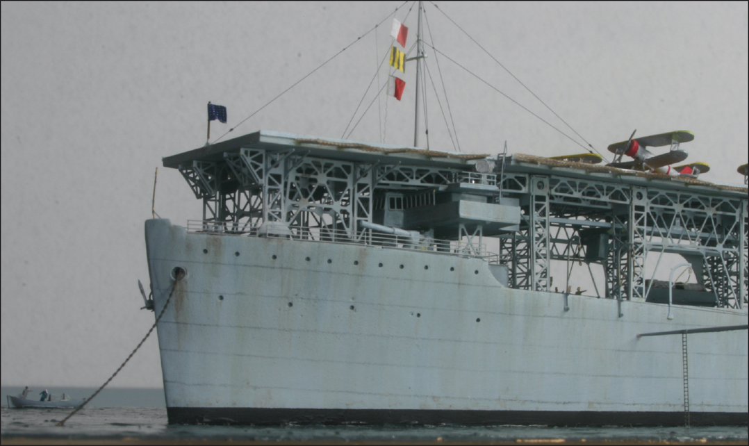
Here we see some of the work that I did on Langley’s hull. The shape of the parts is only approximate, and a lot of them need to be defined much better. Detail is crude, lacking, or inaccurate. The hatches on the ‘hangar deck’ were ground away and replaced with a thinner sheet of plasticard, engraved to represent the hinged plates that gave access to the interior of the ship. The resin bulwarks were cut away and plastic replacements fitted. A coat of grey primer showed up areas of the hull surface that were uneven and required filling and rubbing down, as you can see. All the deckhouses on the after end of the ship had unsightly raised window details trimmed off. They were then covered with five thou plasticard with rather more accurate, square window openings cut into them. Thanks to Peter Van Buren for showing where the windows ought to be. I worked on the assumption that his model was rather more accurate. It also gave me some indication of the arrangement of the trunking to the folding funnels, which ran across the deck. Talk about Health & Safety!
Really that is all that I have done with this diorama. There has been no complicated quayside or buildings to construct. Just one large ship and a few little ones.
The small craft that are doing the dancing in attendance, although they are subsidiary to the main vessel in real life, are not mere bit players in the diorama. It is they that bring it to life. They are every bit as important as the large ship. You could even say that they are more important. They are what make the diorama. Without them you would be looking at a model of a single ship.
When you look at the diorama, your eyes are drawn into it by way of the little vessels. For this reason it is important to take just as much care in making and finishing them as you would with the main vessel.
So let’s get on and build the model.
I bought the Loose Cannon Langley in 2008, at the IPMS US Nationals. There was a very nicely done example of the kit on the competition table, so I knew that it was possible to get a good result. But I didn’t realise just how much work this kit would take. Loose Cannon choose some very interesting subjects, and are to be commended for this. Many ships would not appear in kit form were it not for Loose Cannon. But unfortunately, they take a great deal of effort to bring the detail, and even the shapes of basic structures up to scratch.
I did not have a good set of drawings of the Langley, although I believe they are commercially available. For reference I used photos in books and on the web, such as are found on Navsource and some extremely scrappy little drawings in Whitely’s book on aircraft carriers. I also drew inspiration from Peter Van Buren’s 1/350 model of the ship, and from photos of a builder’s model that appeared on the Steel Navy website, but which seems to differ from the photographic records in many ways, and to be something of an approximation to the appearance of the original ship.

When you open the box for this kit, the thing that strikes you first is the large sheet of photo-etch for all the girders that support the flight deck. It does not have quite the finesse that we have come to expect from Gold Medal or White Ensign, but the thicker brass folds very easily, and certainly looks the business. But looks can be deceiving, and when I began dry fitting everything onto the ship, I discovered that it was too long for the hull. Or maybe the hull master had been built without allowing for the resin shrinking. Every longitudinal component (those marked with a letter on the photo) had to be slightly trimmed at both ends in order for the transverse members to sit at the correct positions along the hull. Towards the stern even more drastic surgery was needed. The rivet counters, or perhaps the diagonal girder counters, will pull me up for it, but I don’t care. It looks OK. The bridge, which can be see nestling under the girders at the break of the fo’c’sle, was built from plastic card and strip, as the kit part was awful, being built up from just vague shapes and none of them square. I don’t know how accurate my interpretation is, but it is not terribly visible on the completed model

This is the base for the model. It has been made much earlier in the process than is my usual practice, but if you are working out the precise positions for the various vessels, you need to know the size and shape of the base you will use. A piece of 6mm MDF forms the surface, and some thick and rough surfaced watercolour paper glued on top. I normally glue the hull of the model directly to the paper, but the bottom of the Langley’s hull was uneven, and the cutout helped to hide this

These are the Battlefleet kits. They are very simple products, and to me some of the shapes look a little ‘stereotyped’, but they look the business as the bustling little handmaids of the big ships. I particularly like the garbage lighter, with its hatches in the side of the hull. It reminds me of a smaller and dumpier version of a ship that is sometimes seen sailing in the River Clyde, loaded down to the gunwales as it goes downstream and high in the water as it returns, having discharged its load of processed sewage into the sea somewhere near Ailsa Craig! I’m sorry, that was too much information, wasn’t it?

These are plastic masters that I made for resin casting. They represent a selection of the barges that were used around US Navy dockyards. The basic hull dimensions were obtained from Navsource, and other visual details found on the same website and also in the background of photos in books by Squadron and Classic Warships Publishing. I do not claim that they are totally accurate. The hulls are made from two pieces of sixty or eighty thou plasticard glued together and cut to size. The superstructure is built from engraved plasticard to replicate corrugated steel sheeting. The window cut outs are backed with more plastic. Rubbing strakes and other details are made from Evergreen strip. After I had made a silicone rubber mould for my own use, and cast copies in resin, I sent the masters off to Harry Abbott of Battlefleet Models, for his own use. He is producing and selling copies with my blessing

Here you see the arrangement that I came up with for the major components of the diorama. As in the Chicago diorama, the Langley is slightly towards the back of the composition. This means I can have three craft in front and one behind without it looking odd. The two rectangular barges occupy the wide end of the larger triangle that has been formed in the base. This is because, sitting side by side, they are wider than either the oiler or the garbage lighter. The barges and the garbage lighter, being tied up alongside the Langley, have to be parallel to her, but the oiler is at a bit of an angle, and this implies movement and ‘life’. When complete, there will be some work boats about the place, and these will tend to break up the straight lines

The kit included a wooden flight deck. It is a personal choice, but I do not like the current trend for wooden decks, as the grain of natural wood looks out of place on a model. I much prefer to see a good paint job on a plastic or resin deck. Although this deck had been laser-cut to give fine transverse planking, the grain of the wood was running fore and aft, which was entirely wrong. So, using the wood deck as a pattern, I made a replacement out of scribed plastic card. But when I came to fit it, I found that the wooden deck had the elevator engraved in the wrong place, right over one of the transverse girders. So what you see here is replacement number two. I am quite pleased with the netting at the edge of the flight deck. I made this from a pair of nylon tights, which I stole from my long-suffering wife. I stretched them by placing an open box inside them, and then painted diluted PVA glue onto the fabric. I blew vigorously onto it to burst all the bubbles in the holes. When dry, the fabric was stiff and could be cut into strips that do not fray and look much more like rope netting than photo-etch does

Here you can see the yard craft completed and painted. The oiler has had pipes and valves put along and across the deck, and some hatches, using photos from United States Navy Destroyers of World War II by John C Reilly as guidance. The garbage lighter has had the deck hatches opened up on one side and the interior hollowed out. Metal masts have been added to both vessels, along with photo-etched railings, davits, etc. The colour scheme for all four craft is primarily black, but I actually painted them in a very dark grey. These were working boats, and proudly grimy. So, following the techniques that I showed in my previous book, I used artist’s oil paints to apply filters, pin-washes, vertical streaking, horizontal scratches and scuff marks, dry-brushing, etc. The use of the colour known as burnt umber is especially useful for grime and rust, which is often depicted in hues that I consider too bright and orangey. The overall effect is something that is fundamentally black, but with a lot of visual texture or variety
And now here are a few photos of the completed diorama. If you are wondering about the aircraft on the flight deck, I must make a confession. The kit included some P-40 Tomahawks, rather than biplanes. Rather than mess around trying to scratch-build them I just found some Japanese ones in the spares box and trimmed the tail fins to make them look rather squarer and American. Rivet counters, leave me alone!
I also tried to mark lines along the hull in pencil to imitate the plating. This was not very successful, and in retrospect I would have been better to have thought ahead and used strips of Bare Metal Foil.