CHAPTER III
MAKING STRAIGHT AND CIRCULAR FORMING TOOLS
Forming tools are made in either straight or circular shapes. Forming tools for the lathe or planer are ordinarily made flat or straight. In some cases a flat formed blade is bolted to a holder, but tools that are to be used very little are often made solid, the formed cutting edge being machined and filed on the flat forged end of the tool. When a number of different tools are needed, it is more economical to make one shank or holder and attach separate cutters or blades of the required form.
The diagram A, Fig. 1, shows a straight forming tool of the vertical or straight-faced type. This style of tool is used on automatic turning machines, etc., especially for large work. As the plan view shows, the rear side is dovetailed to fit the holder which, in turn, is attached to the cross-slide of the machine. The circular type of forming tool B is used in preference to the flat or straight type for many classes of work, especially in connection with automatic screw machine practice, because it is easily duplicated after a master tool for turning it is made. The circular tool can be ground repeatedly without changing its shape. The straight form of tool may also be ground repeatedly without affecting the shape, when it is made with a formed surface which is of uniform cross-section; some straight or flat tools, however, especially when made for producing a comparatively small amount of work, are filed to shape before hardening and when the top of the tool is ground down for sharpening, the shape of the cutting edge changes owing to the clearances. A straight-faced tool A can be made without clearance on angular or curved surfaces, but edges which are at right angles with the axis of the work should preferably be given a slight side clearance; this clearance angle, however, will affect the accuracy of the tool very little as the top is ground away for sharpening, and the error resulting from this cause could be disregarded on many classes of work.
Forming tools are also made which operate tangentially instead of radially; that is, the cutting edge, instead of moving in toward the center of the work, moves along a line tangent to the outside surface being formed. The tool may be mounted on a vertical slide operated by a hand lever, or it may be fed horizontally. When using the cutters shown in Fig. 1, the entire cutting edge comes into action and, in some cases, this results in chattering and springing of the work. With a tangent cutter, it is possible to prevent this trouble by beveling the front end so that the point of the tool begins cutting first and then passes beyond the center of the work, while the remaining part of the inclined cutting edge gradually comes into the working position.

Fig. 1. (A) Straight Forming Tool of Vertical Type. (B) Circular Forming Tool
There are many different methods of making forming tools, but little has been written on this subject in a way which will enable the inexperienced toolmaker or machinist to compute the distances, diameters, or angles so as to produce the required dimensions on the finished work. For instance, if a circular tool is to produce certain diameters on the work, and we transfer the exact ratio of these different diameters from the drawing to the forming tool, we will not be able to get the required dimensions when the cutting edge of the tool is one-quarter of an inch below the center. If we have to make a straight forming tool which, in the machine, is to stand at an angle of 15 degrees, we can, when it is not very wide, use a master forming tool. When, however, the tool is very wide, so that the use of the master tool is impracticable, and it is necessary to mill or plane it to shape, some computation is then necessary in order to make the shape such that it will produce the required dimensions on the work when the tool is held at an angle in the machine. The calculations connected with straight and circular forming tools will be referred to later.
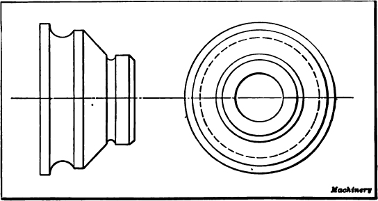
Fig. 2. Example of Forming Tool Work
Making Straight Forming Tools. — The following method of making straight forming tools has proved satisfactory and will produce accurate results if the work is done carefully. Suppose that we are called upon to make the tools for producing with accuracy such a piece of work as shown in Fig. 2, and that a master former is to be made so that at any future time the forming tool can be duplicated at small expense.
The master former may be made as in Fig. 3, being an accurate duplicate of the model with the addition of a shank about an inch and a half in length on each end, these shanks serving as an arbor for the tool. The formed part is milled down to the center, to produce a cutting face for future operations, after which the tool is hardened, tempered and the face accurately ground. To facilitate this face grinding the fixture shown in Fig. 4 is employed, the work being done on a surface grinder. The most essential point to be observed in grinding such a former is to have the cutting face radial, and this is accomplished by the use of this fixture. The fixture is placed on the grinder so that the line of centers is at right angles with the grinding wheel; the center c is removed from the block d, and the grinding wheel is brought to bear on the ball b, which is a running fit in the lever a. This lever is fulcrumed on the block d and is held upward by means of a spring attached to the short arm. With the grinding wheel at rest, the table of the grinder is now run back and forth and the wheel fed downward until it reaches such a position that when it passes over the ball b, the front end of the lever will indicate zero. This shows the operator that the periphery of the wheel is in perfect alignment with the center of the fixture. The center c is then replaced and the master former, with dog attached, is placed between the centers and ground. By the use of the handle e, which engages the knurled head of the adjustable center, the former is turned slightly after each cut across the face until a keen cutting edge on the former is obtained.
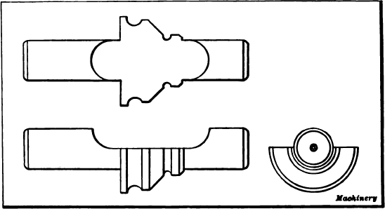
Fig. 3. Master Former used in Making a Straight Forming Tool
The block from which the forming tool is to be made is placed in the vise of the milling machine and roughed out as near to the formed shape as possible, after which the master former is substituted for the milling cutter, as shown in Fig. 5. The cutting face of the master former must stand at the same angle with the vertical as the forming tool is to stand when placed in the screw machine, and it is very essential to observe this point if accurate results are desired. When the proper angle of the former has been obtained, it is secured in position by a wooden wedge tapped in between the cone and the frame of the milling machine. The table is then run back and forth and the forming tool gradually cut to the desired shape by taking light scraping cuts with the master tool.
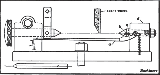
Fig. 4. Device for Grinding Master Former
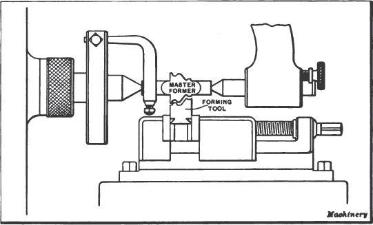
Fig. 5. Making Straight Forming Tool from Master Former
Straight forming tools are sometimes machined in the shaper. One method consists in filing a templet to fit the model and from this making the shaping tool, which, in turn, is placed in the shaper with the face standing at the same angle as will the forming tool when placed in the screw machine. Then the forming tool blank is put in the vise and shaped in the usual way. As the shaper tool inclines backward, the cutting edge has “negative rake” and works with a scraping action so that the cuts must be very light. Before using the shaper forming tool, it is usually advisable to rough out the blank to be formed to approximately the required shape, so that there will be little metal to remove by the forming tool.
The foregoing methods are based upon the duplication of the formers by mechanical means, but when making straight forming tools by the method described in the following, the dimensions of the tool are computed. We have already made it clear that an error will exist if we transfer to the tool the exact differences in the various radii on the work, and it is to overcome this error that we subtract from the dimensions of the work such differences as are caused by the tool standing at an angle in the machine, as will be explained more fully later.
Making Vertical Forming Tools. — The methods referred to in the following represent the practice at the Windsor Machine Co., in the production of the vertical forming tools such as are used on the Gridley automatic machines. These forming tools were made at first by being shaped to the form required, it being necessary for the mechanic to use his best judgment in allowing for changes in hardening, but as tools of different shapes were not affected alike by these changes, it was impossible to be sure of accurate results. To overcome this defect, the vertical style of forming tools are ground after the hardening operation. This grinding of the hardened tools has practically solved the problem of accuracy and has made it possible to turn parts of much more intricate shape, and secure true corners, curves, and angles on the work.
One of the most frequent questions arising in regard to grinding forming tools is the expense, many believing that it takes more time than is actually required and that it is not advisable to grind the tools owing to the cost. Within reasonable limits, the time should not be considered, because when a vertical tool is completed, it will produce hundreds of parts, to say nothing of the accuracy of production and duplicating qualities of the work. At first thought, one might charge all the time consumed in grinding plus the time it would take to finish a tool in the old way, but this is incorrect as much time is saved on the shaper work because it is not necessary to plane the form so accurately when the tool is to be ground afterward, and coarser feeds may be employed. Because of this advantage, very little extra time is required for grinding, and this additional time is certainly offset by the accurate surfaces and measurements obtained on the work.
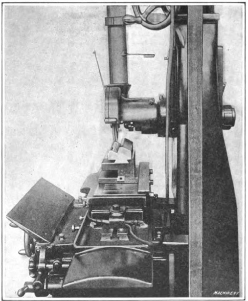
Fig. 6. Grinding a Hardened Forming Tool on Surface Grinder
Before grinding a forming tool, it is first roughed out on a shaper, 0.010 or 0.015 inch being left for grinding. The back of the tool or dovetail is finished to size so that no unnecessary grinding is required. The grinding is all done on a surface grinder fitted with a magnetic plate or chuck. The fixture for holding the tools while being ground is a very simple device and is illustrated in Fig. 6. It is essential that the top and bottom of the fixture be perfectly parallel and also that the fixed edge of the dovetail be true with both edges or sides of the base. If the straightedge on the magnetic chuck is true, obviously this holder can be removed and replaced without affecting the accuracy of the work; it can also be changed end for end, although care should be taken that the holder and magnetic chuck are clean when such changes are made. By inserting a thin piece of steel of the required thickness between the straightedge and fixture, the necessary clearance for the vertical faces of the tool can also be obtained, as will be described more fully later. A few of the many shapes of vertical forming tools that have been ground at the Windsor Machine Co., are shown in Fig. 7. In order to illustrate the general method of procedure in producing these forming tools, the different operations on the particular tool shown at G will be described in detail, as this tool is typical in many respects.
Dimensioning and Laying Out a Forming Tool. — When making the drawing of a forming tool, the draftsman Should make each horizontal measurement correspond exactly with each relative measurement of length on the article to be turned. The vertical measurements should, preferably, be given at right angles to the front face of the tool, so that the mechanic can work directly from the drawing; in this way, the liability of mistakes is lessened and the work can be done more rapidly. Of course, these dimensions at right angles to the face of the tool vary slightly from the actual dimensions on the work, owing to the clearance angle, and must be calculated, as explained in the paragraph, “Vertical Forming Tool Calculations.”
The exact method of procedure when laying out a tool depends, of course, largely upon the form of the cutting edge. Fig. 8 illustrates, in a general way, however, how this work is done. The tool shown by the diagrams A to F, inclusive, is similar to the one illustrated at G in Fig. 7. After copper-plating the front end or working face of the tool (by using a copper-sulphate solution) place the block on a surface plate with side x down; then with a scratch block resting upon a combination of size blocks equal in height to dimension a (see sketch B) plus 0.010 inch, scribe the first of the vertical lines (sketch J indicates how the scratch block is used in conjunction with the size blocks). By using different combinations of size blocks, scribe each succeeding vertical line until all the lines are laid out as indicated at B. The first measurement a is the only one that is made 0.010 inch greater than the dimension on the drawing, this allowance being left for grinding the left side; the distances between the other lines must be precise. Next place the block on surface y (see sketch A), and scribe, in the same manner, all horizontal lines, as indicated at C; then with a protractor set at the required angle, draw lines c–d and e–f, and also the two corner angles, as at D. With dividers, scribe arcs of the correct radius in each corner that is to be rounded. The block is now ready to be roughed out on the shaper.
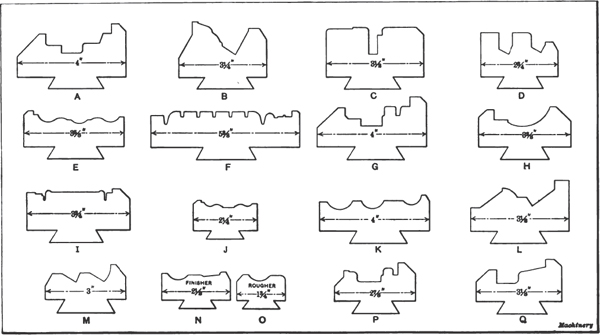
Fig. 7. Various Shapes of Vertical forming Tools which have been Finished by Grinding
It is needless to dwell on the method of removing the stock in the shaper, but when performing this operation, allowances for grinding should be made (as indicated by the dotted lines on sketch E, Fig. 8), 0.007 or 0.008 inch being left on a side; that is, measurements between faces such as g or h (sketch F) should be left about 0.015 inch narrow, while a measurement like k should be about 0.015 inch wide. No allowance need be made on vertical measurements because the same amount can be ground from each surface, so that there will be no change in the measurements. When roughing the tool out in the shaper, it is preferable to plane the surfaces straight or parallel, making no allowance for clearance on the side faces. The amount to be removed for clearance is so slight that it can easily be ground. When the tool has been roughed out, the upper end or working face should be beveled off to the required clearance angle which, at the Windsor Machine Co., is made 12 degrees.
Set of Wheels for Grinding Forming Tools. — When grinding forming tools, the general rule for the selection of wheels, viz., use soft wheels for hard metal and vice versa, cannot always be strictly adhered to. Numerous experiments have shown that excellent results in grinding are obtained by using alundum wheels, different grades and grains being selected according to requirements. The following list gives an ample variety and all the shapes that are required may be obtained by using one wheel or the other and dressing the wheel face off to suit the shape desired on the tool.
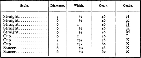
Quite a number of wheels is necessary to secure economical results, but when a stock of wheels is secured the consumption is small if they are handled properly. When first starting to grind form tools, one should not make too radical a change in the shape of a wheel face, but secure another size which is more suitable. In this way, there will soon be a variety large enough so that a wheel can be found which will require but little dressing to reproduce almost any form desired.
Method of Grinding a Forming Tool. — After the tool is hardened, it is ground to the finished dimensions. The first operation is to grind the upper end or working face of the tool. Enough should be ground off to insure sharp corners or edges, without having to grind too much on the formed surfaces. The next operation is that of grinding the formed part of the tool. The dovetailed clamping surfaces should first be inspected to see if they are clean. The tool is then clamped in a fixture similar to that shown on the surface grinder in Fig. 6. The tool shown in this illustration, however, does not correspond in form with the one selected as an example and illustrated in Fig. 8. Naturally, the first surface that should be ground is the one that is highest, thus providing a resting place for the base of the depth gage. All vertical measurements (as held for grinding) should be given from this surface. For measuring vertically when grinding, a micrometer depth gage has proved satisfactory, while for horizontal measurements, a set of size blocks may be employed.
If there is a dimension such as h of, say,  inch (see sketch F, Fig. 8), a 7- by
  -inch wheel of 46-H grade and grain would be about right for grinding. First grind the lower horizontal surface to within 0.001 inch of the required depth; then insert a thin strip of steel between the work-holder and straightedge of the chuck, in order to secure the necessary clearance for the sides of the tool. Use the sides of the wheel to rough off the sides of slot h to within 0.003 or 0.004 inch of the width at the narrowest end (working face) of the tool, grinding first the left side and then the right side. Next, raise the wheel and grind off the top surface of k and also surface N, allowing 0.001 inch for finishing. Adjust the work laterally and rough off surface O; then drop to surface M and grind that to 0.001 inch less than the required depth. Next, raise the wheel far enough to clear the beveled corner to the left of M, and rough off the side surface, care being taken not to grind too much in order to retain dimension g at the narrow end, in proper relation to slot h. Be sure that the strip of steel is at the proper end of the fixture to allow a clearance on this side.
Now take a 6- by  -inch saucer wheel (60-K) and dress off the face and sides, carefully retaining a sharp corner. With the fixture held as for the previous operation, grind the left side indicated by dimension h, great care being taken to grind it smooth and straight. While grinding, the lower edge of the wheel should be down even with the lower surface, and when the side is smooth, feed the wheel down far enough to take off the 0.001 inch from the lower surface that was left when rough-grinding; then feed the wheel to the right, thus finishing the lower surface as far as possible without touching the right-hand side of the slot. Note the reading of the handwheel dial and raise the grinding wheel one or two thousandths inch. Turn the fixture around, adjust the strip for clearance and then grind the other side of slot h until the required width is obtained. Of course, all measurements should be made at the working end or top face of the tool. Continue the grinding operation by feeding down to the same reading previously obtained and then feed horizontally to join the lower surface that was ground before turning the fixture around, thus finishing the slot. Raise the wheel and grind surface I and then side O, measuring from the slot h. Feed the wheel down far enough to take off the 0.001 inch left when roughing; then feed across surface N and the top surface of the part k.
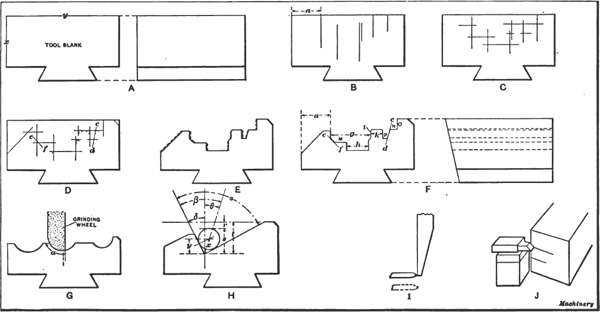
Fig. 8. Diagrams Illustrating Method of Laying Out a Forming Tool, Grinding Curved Surfaces, and Gaging Angular Tools
Turn the fixture around again and adjust the strip for clearance. Place a 6- by  -inch 46-K wheel on the machine and bevel off the left corner of the wheel so that the width of the chamfer is a little less than the width of chamfer e–f on the work. Dish the side of the wheel slightly, so that only the corner does the cutting, and grind the remaining side of g until the width is correct; then feed down until the upper corner of the chamfer is ground to the right depth, after which move the wheel a little to the right and feed down, grinding horizontal surface M to the required dimension; then feed to the left until this horizontal surface joins with the beveled corner. Next dress off the back of a 60-K saucer wheel to the proper angle for side c–d, using the fixture for angular dressing illustrated in Fig. 9. (This fixture will be described later.) Make the face of the wheel slightly narrower than the width of slot P at the bottom; then with work-holding fixture inclined horizontally to give clearance to the side of the slot, grind the left side of slot P until k is of the required width, feeding down until slot P is of the proper depth. Raise the wheel slightly, remove the clearance strip and with the fixture set parallel to the travel of the table, grind the angular side, feeding laterally and down until slot P is of the correct width when the index reading is the same as when finishing the other side. Care must be taken not to touch the straight side when grinding the angular surface, because the cutting edge would be the first to be ground away by the wheel, thus spoiling the tool. This slot can be roughed out with a coarser wheel, if desired, but should be finished with a 60-K to retain the sharp corners at the bottom. In this case, it is not likely that a roughing wheel would be economical to use, because changing wheels and forming or dressing two wheels would offset the extra time required for grinding with a 60-K wheel. Secure a 46-K saucer wheel and form it for grinding the small round corners. The work-holding fixture should be set in different positions so that the same wheel may be used on all the corners of the same radius. The tool is now finished, excepting the beveled surface at the left, and the left side. The beveled surface should extend a little below the largest diameter of the part to be turned, or, in this case, a little below the bottom surface of slot h.
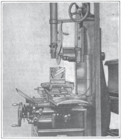
Fig. 9. Fixture on Magnetic Chuck of Surface Grinder is used for Dressing Grinding Wheels at an Angle
In measuring a slot with the size blocks, insert the block or combination of blocks in the slot near the widest end and move them toward the working end of the tool as far as possible. Continue grinding from the side until the block will just pass through at the cutting edge.
When forming tools were first ground at the Windsor Machine Co., a holder that swiveled was employed, but it soon became evident that this holder was unnecessary and, in fact, undesirable owing to the time taken to change it back and forth, to say nothing of the possibility of a mistake caused by not getting it true for different surfaces. It is much preferable to have a plain holder like the one illustrated in Fig. 6 and then use a fixture to dress off the emery wheel to the required angle.
Grinding Angular Surfaces. — The fixture used for dressing grinding wheels at an angle (illustrated in Fig. 9) consists of a block which holds the diamond and is traversed back and forth on an inclined block; the latter, in turn, swivels on a stud at the center of the fixture. The outer end of the inclined block rests on an adjustable screw, which, being movable in a slot, allows adjustment for any position from the vertical to the horizontal. There are two of these adjusting screws so that settings for two angles can be made at the same time, one on either side of the vertical. This swiveling block is set at any required angle relative to the top of the fixture, the top being ground parallel to the base. The fixture is about 4 inches wide, thus giving a good bearing surface for the bevel protractor. A vernier protractor can be set practically to within  minutes of the given angle, and very few form tools require greater accuracy, although, for very fine work, the sine bar may be used in setting the swivel block. By using this truing fixture, one can dress a surface
  inch wide just as accurately to a given angle as a surface 4 inches wide.
The grain and grade of wheels used for grinding surfaces on an angle are governed by the same condition as for straight grinding, except for a forming tool having two angular surfaces which, at the point of intersection, form a sharp corner as, for example, a tool for turning bevel gear blanks. For such work it is well to use a 46-M wheel; this wheel may seem too hard at first, but experience has shown that the best results are obtained with this grade. As little as possible should be left for grinding, and when using a wheel of the grade mentioned, rough out to within 0.001 or 0.002 inch of the size; then, after re-dressing the wheel, the surfaces may be finished smooth and a sharp corner obtained.
The best way to grind forming tools which are to be used for turning bevel gear blanks and similar shapes, is to take a 46-M wheel, say,  inch wide, and dress it down so as to make the width of each bevel in proportion to the width of the surface each side is to grind. The bottom of the angular groove is ground first by setting the wheel central, as indicated at A, Fig. 10, then feeding the wheel down and cutting to the full width of both bevels until the point of the wheel is about 0.002 inch less than the required depth. To grind the remaining surfaces, raise the wheel and move it sideways so that when it is fed down again, the wheel face will slightly overlap the surface already ground, as indicated by the dotted line in sketch B. The wheel is then moved farther up the incline, and so on until the entire surface is finished. In a similar manner, the opposite angular surface is ground. For finishing, re-dress the wheel and repeat the foregoing operation, taking off the 0.002 inch left when roughing. If these operations are performed carefully, a tool can be ground quite quickly without burning it, although it will become quite warm. The angular form of tool and those having large or irregular curves are the only ones that need a templet to work to, as all others can be gaged by direct measurement, using the graduated dials of the grinding machine and regular measuring tools.
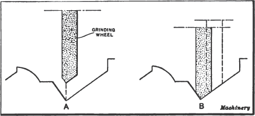
Fig. 10. Method of Grinding an Angular Surface
When grinding sharp square corners, dress the face of the wheel off with a diamond attached to the magnetic chuck. When dressing the side of a wheel, the diamond should not be carried beyond the periphery of the wheel as indicated by the dotted lines in sketch I, Fig. 8, but should stop just before reaching the edge or in the position shown by the full lines, because the diamond breaks the corner of the wheel more or less, if it passes beyond the periphery; therefore, it should be brought up close to the edge and then be returned. A little practice will enable one to grind sharp corners.
Gaging an Angular Tool. — When an angular tool for bevel gear blanks does not have a curved surface in conjunction with the angular surfaces, a mechanic versed in trigonometry can save time by a few simple calculations. The diagram H, Fig. 8, illustrates how the depth of a V-groove can be accurately gaged by using a cylindrical rod and calculating the distance r to the top surface from which the measurement is taken. For a tool of the form illustrated, the two angles and the distance t are always given. As depth t is down to a sharp corner, it is difficult to determine it by direct measurement but by laying a cylindrical rod in the groove and measuring down to this rod, an accurate measurement may be obtained. As dimension r is the one required, the distance s from the top of the rod to the apex of the angle must be determined. As a rod lying in a V-slot will always center itself, a line drawn through the center of the rod and the apex of the angle will be equidistant from each side of the angle, thus giving the angle β which is one-half of angle α. A line drawn through the center of the rod and through the point of contact on either side of the angle, will be at right angles to that side. This line, and the one extending from this point of contact to the apex of the angle and the line extending from the apex to the center of the rod, forms a right-angle triangle of which one side (radius of the rod), and angle β are known, so that dimension x may be obtained. (Hypotenuse equals side opposite divided by sine.) Drawing a vertical line through the apex of angle α and also one at right angles to this line through the center of the rod, gives a right-angle triangle of which dimension y is desired. Angles β and δ being known, angle θ is obtained easily, and, having dimension x, dimension y may also be obtained. (Side adjacent equals hypotenuse times cosine.) Therefore s will equal y plus one-half the diameter of the rod, and this dimension, subtracted from t, will give the required measurement r.
Points on Grinding Vertical Surfaces. — When grinding the sides of vertical surfaces of a forming tool, any neglect or carelessness will be manifest in the action of the tool when it is being used. Care must be taken to see that the wheel is not allowed any side play when finishing vertical surfaces, as otherwise when the wheel leaves the tool at the end, it will grind the corners back on account of the gradual lessening of the wheel area in contact, thus forming a convex surface adjacent to the cutting edge. This will allow the stock, when the tool is in use, to rub on the side below the cutting edge, which causes a “loading” of the tool and makes it impossible to secure a good finish on the work. As this lack of clearance caused considerable trouble, the Windsor Machine Co. adopted the plan of grinding a clearance on all straight side surfaces, to avoid any rubbing of the work or loading of the tool when in use. This clearance is obtained, as previously mentioned, by inserting a thin strip of steel between the edge of the grinding fixture (see Fig. 6), and the straightedge on the magnetic chuck, at whichever end of the fixture needs to be inclined outward in order to provide clearance for the cutting edge. This strip should be thick enough to provide a taper of about 0.035 inch per foot, which is approximately the minimum amount for good results. While more clearance would be better as far as the cutting action of the tool is concerned, it would result in too great a change of length as the tool is ground away on the top for sharpening. In most cases, however, a difference in length of 0.003 to 0-005 inch one way or the other is immaterial, especially on large work. Obviously, this liner can be inserted at either end of the holder, depending upon which side of the tool is being ground for clearance. This clearance is only necessary on straight sides as all curves and surfaces on an angle, no matter how slight, will clear themselves. The only exception as to curves is when one joins a straight side; then it should be ground at the same time that the straight side is ground for clearance.
Joining a Vertical Side and Beveled Surface. — Another grinding problem met with when finishing a forming tool similar to that shown at L in Fig. 7, is that of joining a straight or vertical side and a bevel, grinding the clearance on the vertical side and, at the same time, neatly joining it with the beveled surface. First, all the surfaces of the forming tool should be ground straight or without clearance; then a thin strip of steel, as previously stated, should be inserted to give the proper slant to the vertical side for obtaining the necessary clearance. This, of course, will throw the bevel out of true so that the wheel, if fed down close enough to it, would grind at the bottom of this surface before touching the top or cutting edge. To overcome this, the working face or upper end of the forming tool should be raised enough so that when a test indicator, attached to the wheel guard, is run along the beveled surface, the pointer will remain stationary. When finishing sides or vertical surfaces, the table should be traversed back and forth by hand, because a good surface cannot be obtained when the power feed is used, on account of the jar of the mechanism when it reverses. When grinding ordinary forming tools, little difficulty will be met with if the mechanic adheres to the use of the grain and grade of wheels recommended in the foregoing, and bears in mind that this is an operation wherein the old saying, “haste makes waste” is especially true.
Grinding Curved Surfaces. — The making of forming tools for producing irregular curves and surfaces is quite a different proposition from that of making tools having only straight and angular surfaces and here is where experience in grinding tools is required, because these curves are affected by the clearance angle; hence, the curve on the wheel is not exactly the same as the curve to be reproduced on the work. Obtaining the required shape and size, depends largely upon one’s ability in dressing the wheel to the correct curvature by hand. For instance, when grinding a tool which is to have a circular cutting edge, the wheel is first dressed to fit a true gage of the required radius and when finish-grinding, the wheel face is slightly altered by hand dressing to compensate for the angularity of the cutting face. In other words, it is necessary to make the wheel face slightly elliptical in order to secure a circular cutting edge along the beveled face at the top of the tool.
In grinding circular surfaces, it is advisable to never work on more than a quarter of a circle at a time because the work can be done more rapidly and better by following this rule. For example, to grind the tool illustrated at G in Fig. 8, the wheel should be dressed off so as to form a curve extending a little beyond the center at the bottom, as indicated by arrow a, to allow for joining the two halves of the surface neatly and smoothly. When grinding a curved surface of this kind, first grind one side and then note the dial reading on the machine. Next turn the holder around and grind the other side, feeding the wheel down to the same depth as shown by the previous reading. It is also necessary to feed the wheel laterally somewhat in order to compensate for the angularity of the top or working face of the tool. The form of the wheel must also be changed slightly in order to secure a true circle at the cutting edge.
As an example, illustrating the grinding of curves of large radii, let us assume that a tool is to be ground and that the radius of curvature required on the work is  inch. Secure a partly worn 6- by 1-inch cup wheel of 46-I grain and grade and one that is a little wider than half the width of the curve. Dress off the wheel to fit a
  -inch radius gage and then grind one side of the curve as indicated by the diagram G, Fig. 8, just cleaning up the side. Next raise the wheel and turn the fixture around for grinding the other side. Move the wheel over, and down, gradually, to the same reading as shown by the dial on the handwheel of the machine. Doubtless this will not make the rough planed recess either deep or wide enough so that the wheel must be fed down, say 0.002 or 0.003 inch, and laterally proportionately. When making these adjustments the dial readings should be noted. Now raise the wheel slightly and turn the fixture around again; then by moving the wheel over and down, the first side should be ground until the dial registers the same as for the other half of the curve. This operation must be repeated until the required depth is obtained, care being taken to keep the center of the curve in the proper place. The wheel must be dressed off at intervals for grinding the proper shape so that the cutting edge in the plane of the working face of the tool will be a true radius. All gages or templets for irregular surfaces and curves should be made to correspond with the curve required on the work and be held in the same plane as the working face of the tool, or, in this case, on a slant of 12 degrees, which is the required angle of clearance. No allowance should be made on the gage, the latter corresponding to the measurements required on the work and the tool being ground until the gage accurately fits the cutting edge, when held parallel with the top or working face.
While the wheel should be dressed to the required form with a diamond tool, the following trick is often worth knowing: After the curve on the work is ground approximately to shape and size, secure part of a broken 46-K emery wheel and using a flat surface, run this piece lightly back and forth once or twice over the working face of the wheel. Coarse emery cloth may also be used. As this operation dulls the wheel face, it must not be done until the tool is ground almost to the finished size; moreover, one must not attempt to secure the correct shape by dressing the wheel in this way. As previously mentioned, the shape should be obtained by dressing with the diamond tool, and not more than 0.001 inch be taken off of the tool after the emery wheel is smoothed with the emery brick. If there is a greater allowance, the tool is liable to be burned, when grinding with the dulled face of the wheel. When grinding curves, the wheel, as it does not feed laterally as in flat grinding, leaves fine scratches, the coarseness of which depends on the grain of the wheel; therefore a piece of emery wheel or cloth is used on the wheel prior to the final finishing operation, merely to obliterate these scratches. Ridges, however, cannot be ground out with a wheel that has been dulled in this way.
Wheels to use for Grinding Curved Surfaces. — When grinding curved surfaces, the grade of the wheel should be varied according to the radius of the curvature. For all radii above  inch, the use of a 46-H wheel is to be recommended. Although this grade is a little harder to shape than a softer grade, and secure a smooth surface, it will cut free without glazing or losing its form. For comparatively small radii, however, this grade will not hold its shape very well, and a 46-K is much more serviceable, down to a
  -inch radius. For a
  -inch or a
  -inch radius, No. 46 grain is too coarse for good results and a grain and grade of 60-K should be employed. For rapid grinding, 46-H wheels should be used on all broad surfaces such as those illustrated at C, F, I and Q, Fig. 7. This grain and grade of wheel should also be used for grinding sides or vertical surfaces whenever a sharp comer is not required, and even then it is well to rough-grind with this wheel, finishing with a finer wheel. A grain and grade of 46-K gives a good finish when a small radius is to be left in a comer, but if a sharp comer is necessary, a 60-K wheel should be used, care being taken to keep it from glazing. If the wheel is touched frequently with the diamond tool, it will last longer than if allowed to glaze over excessively.
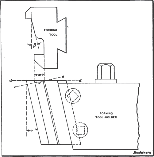
Fig. 11. Elevation and Plan of Forming Tool showing how Clearance Angle affects Dimensions of Tool
Vertical Forming Tool Calculations. — The vertical forming tool, as used on the Gridley automatic, is held on a 12-degree angle for clearance, but when grinding, the tool is held horizontally (as shown in Fig. 6) so that it is necessary to make an allowance on all radial as well as angular measurements, because there is a difference in the distance from one step to another on the tool, or a slight change in the angle, depending upon whether the measurement is taken along the top face of the tool or at right angles to the front face. To illustrate, if dimension x, Fig. 11, represents the distance that is to be reproduced on the work, it will be necessary, when grinding the tool, to make the depth y, measured at right angles to the front face, slightly less than the required depth x, owing to the angular position of the tool. Evidently the difference between x and y will depend upon the clearance angle α. The depth of y will equal dimension x multiplied by the cosine of angle α, or the side adjacent equals the hypotenuse times the cosine of α. For example, the part made with the tool shown at C, Fig. 7, should have a radius difference of one inch from the body part to the outside of the flange produced by the slot in the tool. As the top face of the tool is at a 12-degree angle while grinding, the slot should be ground to a depth equal to the radial dimension required on the work, times the cosine of 12 degrees, or 1 × 0.9781 = 0.9781 inch, instead of one inch.
Allowance must also be made when grinding angular surfaces. For example, suppose the angular surface of the forming tool illustrated in Fig. 11 is to reproduce an angle β of 15 degrees on the work. It is evident that in order to grind the tool to an angle β of 15 degrees on the top or along the cutting edge, the angle at right angles to the front face of the tool must be slightly less, owing to the clearance angle. For instance, if angle β is to be 15 degrees when measured in the plane d–d, the angle when measured along the plane e–e (which is square with the front face) will be a little less than 15 degrees and will represent the angle to which the face of the grinding wheel should be trued.
To determine the angle at which the tool must be ground, multiply the tangent of the angle required on the work, by the cosine of the clearance angle; the product equals the tangent of the angle when measured at right angles to the front face of the tool. Thus, taking the tangent of 15 degrees, which is 0.26795, and multiplying by the cosine of 12 degrees, or 0.97815, we have 0.26795 × 0.97815 = 0.26209, which is the tangent of 14 degrees 40 minutes, nearly; therefore, the grinding wheel should be dressed to this angle.
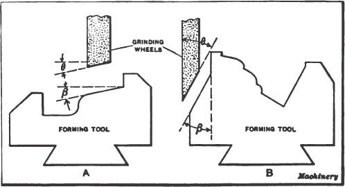
Fig. 12. The Angle of the Grinding Wheel must be varied slightly owing to Clearance Angle of Forming Tool
For angles larger than 45 degrees, it is preferable to work from a vertical line, or from a line at right angles to the axis of the work, instead of parallel to the axis. When working from a vertical line, divide the tangent of the required angle by the cosine of the angle of clearance, instead of multiplying, in order to obtain the tangent of the angle measured at right angles to the front face of the tool. The difference between the two methods is illustrated by the diagrams A and B, Fig. 12. When angle β is measured in the plane of the top face of the tool and from a horizontal line parallel to the axis of the work (as at A), angle θ of the wheel face equals tan β × cosine of clearance angle. On the other hand, when angle β is measured from a vertical line at right angles to the axis of the work (as at B), tan θ of the wheel face equals  . Suppose angle β (sketch B) is 30 degrees; then, dividing the tangent of the required angle by the cosine of the clearance angle, we have:
  = 0.50024, which is the tangent of the angle the wheel should be trued to, or approximately 30 degrees 33 minutes. Thus, we have the following very simple rules for obtaining grinding angles or the angle of the tool measured at right angles to the front face:
When working from a vertical line (at right angles to axis of Work) the tangent of the grinding angle equals the tangent of the angle of production (angle required on work) divided, by the cosine of the angle of clearance. When working from a horizontal line (parallel to axis of work) the tangent of the grinding angle equals the tangent of the angle of production, multiplied by the cosine of the angle of clearance.
Circular Forming Tool Calculations. — To provide sufficient periphery clearance on circular forming tools, the cutting face is off-set with relation to the center of the tool a distance C as shown at B, Fig. 1. Whenever a circular tool has two or more diameters, the difference in the radii of the steps on the tool will, therefore, not correspond exactly to the difference in the steps on the work. The form produced with the tool also changes, although the change is very slight, unless the amount of off-set C is considerable. Assume that a circular tool is required to produce a part having two diameters as shown. If the difference D1 between the large and small radii of the tool were made equal to dimension D required on the work, D would be a certain amount over-size, depending upon the off-set C of the cutting edge. The following formulas can be used to determine the radii of circular forming tools for turning parts to different diameters:
Let R = largest radius of tool in inches;
D = difference in radii of steps on work;
C = amount cutting edge is off-set from center of tool;
r = required radius in inches;
then:

If the small radius r is given and the large radius R is required, then

To illustrate, if D is to be  inch, the large radius R is
  inch, and C is
  inch, what radius r would be required to compensate for the off-set C of the cutting edge? Inserting these values in Formula (1):
 =1.0014 inch..
The value of r is thus found to be 1.0014 inch; hence the diameter = 2 × 1.0014 = 2.0028 inches instead of 2 inches, as would have been the case if the cutting edge had been exactly on the center-line of the tool.
Most circular forming tools are made without top rake, that is, the cutting edge is in a horizontal plane, as illustrated in Fig. 1. Tools made in this way are especially adapted for cutting brass but may not work entirely satisfactorily on tougher and harder metals. The amount of top rake for circular tools varies from o to approximately 18 degrees. When a circular forming tool is given top rake, corrections for the diameters of different steps must be made, the variation in diameter depending upon the angle of rake. The rather lengthy mathematical calculations involved are given in full in MACHINERY’S Reference Book, No. 101, “Automatic Screw Machine Practice,” page 20.
Grinding Notch in Circular Forming Tool. — The drawings A, B and C, Fig. 13, illustrate methods which are commonly used for making circular forming tools. The two saw cuts opposite the working side of the tool are intended to relieve the strains due to hardening. Before cutter A can be used the portion indicated by the dotted lines must be ground off. The method described in the following is intended to facilitate this operation. The formed surface of a circular tool must be polished to remove the scale if good results are desired. For this reason most forming tools are made as shown by Sketch A, and after the cutter is hardened and polished, a gash, as shown at B, is ground into the cutter, after which the cutter is ground as indicated at C. A wide tool made in this manner will require considerable time for grinding in order to remove the metal without drawing the temper of the tool. On the other hand, if the tool was originally milled before hardening, as shown at C, it would be almost impossible to polish the tool after hardening. The simplest and most effective means for overcoming this difficulty is indicated at D; the cutter is made with an extra slot, as shown, and after the tool is hardened and polished, the piece y is easily broken out, without injury to the cutter, by driving in a wedge as at x. The cutter may be held in a bench vise and only a slight tap of the hammer is necessary, after which the cut can be quickly finished off with an emery wheel. This method will save considerable expense in the making of circular forming tools.

Fig. 13. Methods of Cutting Notch in Circular Forming Tool
Making Concave Forming Tools in Milling Machine. — Fig. 14 illustrates a method of making a concave forming tool such as is used for backing off convex milling cutters. This tool has, of course, the same shape for its entire depth so that it may be ground and reground without changing its original form.
In the illustration, B represents the tool which is held in the holder A at an angle of 76 degrees with the table of the milling machine, this giving to the tool the proper cutting clearance. The first thing to be done, after placing the tool in the holder, is to mill off the top of the tool so that it will be parallel with the table of the machine. A semi-circle of the desired radius is then drawn on the back of the tool, and with any cutter that is at hand, it is milled nearly to the mark, care being taken not to go below it. For finishing the cutter, a plug C is made, the end being hardened and ground in a surface grinder. This plug is held in a special holder D, which fits the spindle of the milling machine, and when it is set so that its axis is perpendicular to the tool, the spindle of the machine should be firmly locked. Now, by moving the platen of the machine backward and forward by hand, the plug can be made to cut a perfect semi-circle in the tool.
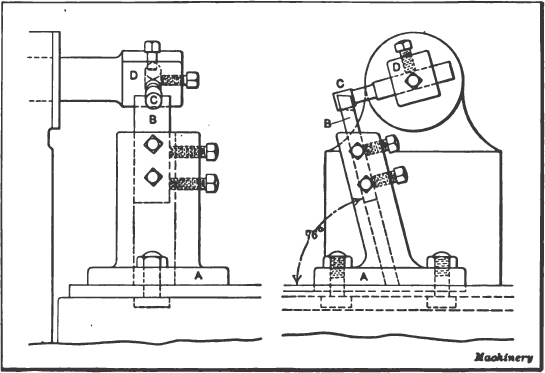
Fig. 14. Making a Concave Forming Tool in the Milling Machine
It is good practice to plane a little below half of the diameter of the plug, thus allowing some stock to be ground off after the tool is hardened. In hardening, these tools usually come out very satisfactorily, but, if any distortion takes place, it will be from the sides, and may be readily remedied by a little stoning. By using the concave tool for a planing tool, a convex tool may be formed, but in doing so care should be taken that both tools stand at an angle of 76 degrees with the bed of the machine. This shape of tool would be used for backing off a concave cutter.
Making Forming Tools for Gear Cutters. — The making of a forming tool for forming gear cutters is not work that is frequently given to the toolmaker, but there are some instances when a special gear cutter is wanted and lack of time prevents having it made by the cutter manufacturer, who is not always very prompt in filling such orders. The ordinary practice is to lay out the tooth curve full size or several times enlarged, and then make master tools to this drawing, by which the formed tool is planed. Following this method, it is necessary to make a special master planing tool for each side of the tooth and planing tools for the curves at the bottom; these operations combined with the method of using the tools and making the necessary corrections for the distortion due to the angle at which each tool is set in planing, are all likely to lead to inaccuracies in the tooth curve, making the results anything but satisfactory. By the following method (which was described by John Edgar in MACHINERY, July, 1914), all the multiplied inaccuracies incident to copying from this original draft are omitted. This method consists of generating the forming tool direct without any intermediate steps, and by mechanical means that alone determine the shape of the tooth curve, so that a correct involute curve is obtained without any approximations whatever.
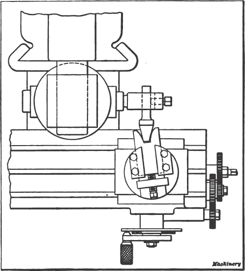
Fig. 15. Milling Machine set op to generate Forming Tool for Gear Cutters, with a Rack-shaped Tool
Probably the greatest drawback to the first method of procedure referred to, is the necessity of making the original drawing of the tooth curve, there being so many methods in use that are mere approximations. Such methods are all well enough for the purpose of representing gear teeth on a drawing, but if it is attempted to make the teeth themselves to these layouts, trouble is liable to be the result. Almost any toolmaker worthy of the name can produce a tool very close to the original curve; but the proposition of getting exactly the original curve is a job that must be left to some mechanical means if we are to get the closest possible degree of accuracy. This means is found in every toolroom and is the universal milling machine. For the operation of generating the tool, a universal milling attachment is required, which may make the use of the method impossible in some cases; but these attachments are now commonly found in the toolroom in connection with the milling machine.
Generating Forming Tool With Fly Cutter. — Fig. 15 shows the machine arranged for using the rack-shaped fly cutter. The forming tool is clamped in a special chuck held in the spindle of the dividing head, which is set in the vertical position. The head is shown set up with the change gears as for spiral cutting, the pitch for which the gears are chosen being equal to the circumference of the pitch circle. The universal spindle of the attachment is set at right angles to the axis of the main spindle and parallel to the direction in which the table travels. When set up in this manner, the machine is ready to generate the involute sides of the forming tool, by using a fly cutter that is shaped like the tooth of a rack of the same pitch. The process is similar to that used in some way in all generating machines. By setting the top of the forming tool blank at the height of the axis of the cutter spindle, and the fly cutter so that the cutting plane passes through the center of the cutter spindle, next adjusting the fly cutter to produce a gash of the proper depth, and then starting the machine and throwing in the feed for the table, we can generate the tooth space shown. This space is of the correct shape at the top of the tool only, as the angle of the fly cutter with the top of the forming tool affects the shape at all other positions deeper in the tool. A tool made in this manner would appear as shown at A in Fig. 16, and to make it of use as a forming tool it must be relieved up to the top for clearance. This can be done by filing or other means, so that the finished tool would have a 20-degree clearance (as indicated by the dotted line at B), extending all around the form. With the fly cutter made to close dimensions, the space generated will be of the correct width at the pitch line and to depth; and a forming tool made with it would likewise be of the correct size in relation to thickness and depth.

Fig. 16. Shape of Tool produced by Fly Cotter when Top of Blank is at Height of Cotter Spindle Axis
The necessity for relieving the tool after generating may be avoided by setting the fly cutter as shown in Fig. 17, 20 degrees being chosen as giving plenty of clearance for the tool in the forming and backing off of the cutter. If the cutter teeth are to be given more than the ordinary amount of relief, the angle should be increased. With the use of the fly cutter in this position, a correction will have to be made to counteract the angle at which it is set. This is done by making the angle of the fly cutter such that the angle on a line parallel with the top of the forming tool will be twice the pressure angle. The corrected angle of the side of the fly cutter may be found by the formula:
Tangent of angle of side of fly cutter = 
where α = pressure angle and β = clearance angle.
The included angle of the tool is twice the angle of the side, and the height at which the forming tool is set above the center of the cutter spindle is found by trial, by setting the fly cutter as shown in Fig. 17 and bringing the forming tool to the height of the tip of the fly cutter. This height is, of course, dependent on the radius of the circle swept by the fly cutter. The fly cutter should be set to sweep as large a circle as possible, to give the least possible amount of concavity to the forming tool. The shape generated by the fly cutter is nearly correct throughout the thickness of the forming tool when the latter is thin as compared to the sweep of the fly cutter; and the forming tool can be sharpened by grinding across the top face without greatly changing its form. The clearance, as produced in the case of the fly cutter set according to the preceding instructions, is not adapted to work that requires side relief, as in the case of small numbers of teeth, nor for bevel gear cutters.
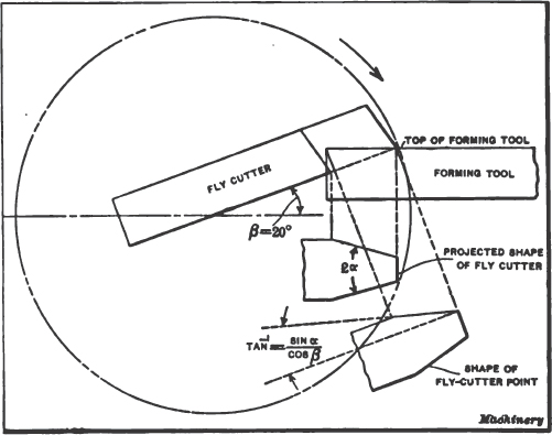
Fig. 17. Method of Setting Fly Cutter to Obtain the Required Clearance on the Forming Tool
This method of generating a forming tool is especially valuable when it is desirable to make cutters for any special number of teeth, when a standard cutter is not satisfactory.