32 Advanced Principles of Minimally Invasive Vertebral Body Stabilization in Severe Benign and Malignant Fractures: Stent-Screw Assisted Internal Fixation
Alessandro Cianfoni and Luigi La Barbera
Summary
The anterior and middle columns of the spine supports about 80% of the overall load across the spine. After vertebral augmentation the repaired vertebrae may refracture around the stabilizing cement or the refracture can involve the middle column of the vertebral body by fracturing posterior to the bone cement previously used in the augmentation procedure. The importance of the middle column has traditionally been underemphasized but is important to consider to maintain vertebral body stability given its weight bearing role and the fact that this area is typically not augmented with bone cement during most vertebral augmentation procedures. Osteolysis of the weight bearing portions of the vertebral bodies may be seen with osteolytic metastases. Although pedicle screw and rod fixation of the spine is commonly used in cases where the metastatic disease has compromised the stability of the spine, stand-alone vertebral augmentation may be another viable option to provide pain relief and stability to the spine. The technique of screw-assisted internal fixation (SAIF) was developed to address the limitations of stand-alone vertebral augmentation and is performed with a combination of vertebral body stents and percutaneous cannulated and fenestrated transpedicular screws. The vertebral body stent has advantages over balloon kyphoplasty in that the stent preserves the vertebral body height after the balloon that was used to expand it has been removed and the metallic mesh of the stent helps to control and confine the cement injection thereby making the stent more optimal for use in cases of severe fracturing or prominent osteolysis. In cases where additional support is necessary, such as with middle column fractures or fractures of the pedicles, the stents can be joined to screws placed using a transpedicular technique and cemented in place by injecting bone cement through the cannulated and fenestrated screw. The SAIF technique represents an image guided 360° fusion of the incident fracture level that is much less invasive and has even biomechanical stability than a traditional spanning pedicle screw and rod construct. The SAIF technique has also been shown to reduce the fracture risk of the superior endplate and the posterior vertebral body wall as compared to vertebral augmentation alone. The SAIF technique can be performed as a stand-alone construct or along with traditional spanning spine instrumentation and can be used to obviate or reduce the need for more invasive surgical techniques.
Keywords: screw assisted internal fixation, vertebral body stent, vertebral refracture, middle column, transpedicular screw
32.1 Introduction
Vertebral augmentation (VA) has been extensively used for pain palliation and stabilization of vertebral body (VB) fractures due to trauma, osteoporosis, and tumors.1–3
32.2 Osteoporotic Fractures
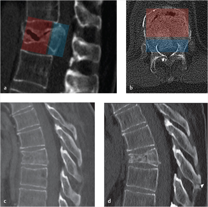
Osteoporotic vertebral fractures can occur spontaneously or due to trauma, generally a compressive load injury mechanism involving the VB.4 Both the anterior and middle columns together support about 80% of the overall spinal load (i.e., muscle forces and body weight) and are most commonly affected. The spectrum of severity ranges from mild and stable compression fractures,5 affecting the disk–end plate region and leading only to minor deformity to unstable fractures with a high-degree of osseous fragmentation, collapse deformity, middle-column involvement, pediculo-somatic junction fracture, and kyphotic deformity6,7 (▶Fig. 32.1a, b). The underlying poor bone quality surely represents a risk factor8,9 and might prevent osseous healing, potentially evolving toward the creation of osteonecrotic clefts10 and, together with the detrimental effect of the increased bending momentum due to kyphosis at the fracture level,11 might be responsible for fracture progression (▶Fig. 32.1c, d).
Cement VA is widely used to treat fragility fractures, palliate pain, restore axial load capability of the VB, and arrest fracture progression.12
Ideally, VB reconstruction, height restoration, and homogeneous cement augmentation should be obtained with bone cement filling the two anterior thirds of the VB from superior to inferior disk end plates on both sides of midline, especially for the most severe of these fractures.
In reality, vertebroplasty is not intended to restore VB structure or height, and balloon kyphoplasty (BKP) has not been proven to guarantee sufficient height restoration, either due to the fact that the balloon tamps expand following the path of least resistance, or due to the deflation effect between balloon removal and cement injection. Moreover, the polymethyl methacrylate (PMMA) cement does not have adhesive properties to ensure stability in highly fragmented osseous structures, and the cement might distribute into the fractured VB in a heterogeneous and unpredictable manner. The cement may extend around the trabeculae and into intra-osseous clefts and it is not always possible to safely augment the entire VB, especially the bone adjacent to the intervertebral disk and end plates. Cement injection, usually monitored with fluoroscopy or CT imaging, is halted if cement tends to leak outside of the VB, into veins or if it approaches the posterior third of the VB. The termination of the cement injection is for the purpose of minimizing the risk of epidural leakage.
Following VA, refracture of the treated VB is a well-known and reported event.13–17 The refracture usually implies subsidence of the non-augmented portions of the VB around the cement cast18 (▶Fig. 32.2). This occurrence might be asymptomatic or be accompanied by pain recurrence. The refracture may be simply a minimal remodeling of the VB around the cement augmentation or it may manifest as a more prominent collapse of the non-augmented portions of the VB.
Fig. 32.1 Osteoporotic fracture: anterior and middle-column involvement—fracture progression. (a, b) An osteoporotic T12 compression fracture involving anterior (transparent red) and middle (transparent blue) columns, with gas-filled cleft. (c) A mild T8 compression fracture, with minimal height reduction, treated conservatively evolves into a higher degree of compression deformity and kyphosis (d). Arrowhead in d points to a new distraction fracture of the spinous process.
Fig. 32.2 Refracture of a treated vertebral body (VB). (a, b) An osteoporotic L1 compression fracture that has been treated with vertebral augmentation (VA) using the SpineJack shows an unfilled portion of the VB inferior to the implant and the cement (white arrows in a). A follow-up X-ray performed a few weeks later shows the unfilled portion in the inferior portion of the L1 VB has collapsed against the bone cement (white arrows in b).
A less frequent event is the refracture of the middle column, at the junction between middle and posterior third of the VB where most commonly the junction between cement-augmented and non-augmented VB is located.19 These fractures are characterized by involvement and retropulsion of the posterior wall and eventually result in catastrophic splitting and separation between augmented anterior portion of the VB and middle column (▶Fig. 32.3). This may also be accompanied by a kyphotic deformity at the incident level. Such fractures are not frequent and are largely unreported but when they do occur they pose a real therapeutic challenge.20,21 These fractures may be repaired by surgical decompression of the central canal, corpectomy and grafting, and posterior stabilization, but this is a very invasive surgical procedure that is associated with significant morbidity and mortality risk, especially in elderly patients with scarce bone quality.22
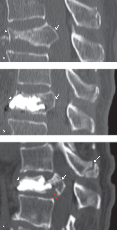
Fig. 32.3 Refracture of the middle column in a treated vertebral body (VB). Mid-sagittal sequential computed tomography (CT) images of an osteoporotic compression fracture (a), with severe collapse of the anterior column (arrowhead in a) and involvement of the middle column with posterior wall retropulsion (arrow in a). After technically successful vertebral augmentation (VA) (b) there is height restoration of anterior column (arrowhead in b) and reduction of posterior wall retropulsion (arrow in b). The middle column remains non-augmented, as in almost all cases of VA. After 6 weeks the patient presented with recurrent severe back pain. The follow-up CT (c) shows maintained fracture reduction at the anterior column (arrowhead in c) but refracture of the middle column with cleavage at the junction between augmented of non-augmented portions of the VB (red arrow in c), and increased posterior wall retropulsion (white arrow in c). There is also focal kyphosis and spinous process fracture (dashed arrow in c) at the adjacent cranial level.
In our anecdotal experience these refractures occur mostly, although not exclusively, in the lumbar region, likely due to a combination of higher loads (both forces and bending moment)23,24 that are accentuated by the kyphotic shape of the fractured vertebra.11
The importance of the middle-column stability might be indeed largely underestimated since the load-bearing capacity of the vertebra is usually referred to the anterior column as a whole structure, totally neglecting the important role of the middle column. Furthermore, the middle column, with the posterior third of the VB, the posterior wall, and the pediculo-somatic junctions, remains relatively non-augmented, even after satisfactory cement augmentation due to the safety measure to avoid cement dispersion too close to the posterior wall. The middle column, after cement augmentation, if observed on an axial post-procedure CT image, might be regarded as a “bare area,” not reinforced, and therefore a potential point of weakness of the vertebra (▶Fig. 32.4). Finally, some authors have reported the cement augmentation of the pedicles and pediculo-somatic junction, the so-called pediculoplasty,25 but it should be considered that main stress forces at the level of the pedicles and pediculo-somatic junction are tensile, and PMMA is known to have optimal resistance to compressive loads rather than to tensile ones.26
Another aspect to consider is the transition between the augmented anterior portion of the vertebra that is completely filled with high-modulus bone cement, and the middle column, which is much weaker, particularly when osteoporosis is present. The result is a load intensification effect on the middle column, possibly explaining the collapse seen in clinical practice. Standard VA might therefore represent an under-treatment in osteoporotic fractures with middle-column involvement.
32.3 Neoplastic Osteolysis
Spinal osteolysis may cause severe instability, leading to fractures and neural compression.27 Stability restoration is therefore of paramount importance in the treatment of lytic spinal tumors. To prevent or arrest vertebral collapse in patients with lesions affecting the weight-bearing portions of the vertebrae, posterior surgical fixation is widely used, but should be accompanied by anterior-column stabilization, either with corpectomy and grafting or with cement augmentation.28,29 Posterior fixation, however, may not be feasible in patients with advanced disease, multilevel lesions, and poor bone quality and corpectomy, and grafting is highly invasive and carries significant morbidity risk especially in fragile neoplastic patients.30
Stand-alone VA is considered a viable option to achieve pain palliation and reinforce the anterior column,2,3,31 but when the osteolysis causes extensive destruction of the cortical boundaries of the VB, the injection of cement may be challenging or impossible.32,33 Cement distribution in these highly destroyed vertebral bodies might be unpredictable, uneven, or result in early extra-vertebral leaks leading to insufficient augmentation and stabilization or to clinical complications including vascular migration or neural compression.
Fig. 32.4 “Bare area”: non-augmented middle column following cement augmentation. In the upper row, lateral fluoroscopic image (a) postaugmentation of L2 and L3 with vertebroplasty technique. The augmentation result and cement distribution can be considered satisfactory but if the augmented vertebral bodies are seen on axial computed tomography (CT) images (b, c), the middle column (transparent red) remains non-augmented and therefore relatively unprotected. This “bare area” is highlighted with transparent red color in b, c, and e. Analogous findings in another case displayed on the lower row, (d and e) showing the result of a kyphoplasty performed with vertebral body stenting (VBS) technique. Even in this case, with larger amount of injected cement, the axial CT shows the “bare area” in the middle column (transparent red in e).
32.4 SAIF Technique
To address the limitations of standard VA in the most severe osteoporotic fractures and neoplastic lytic lesions, we have recently proposed the use of a new technique called “stent screw-assisted internal fixation (SAIF).”34
The SAIF is performed by combining the use of VB stent (VBS) (De Puy Synthes—Johnson & Johnson) augmentation and insertion of percutaneous cannulated fenestrated transpedicular screw (Injection pin—2B1, Milan, Italy).
The VBS is a balloon-expandable barrel-shaped metallic device, which is inserted unilaterally or bilaterally via a transpedicular access. Upon expansion, the VBS keeps the created cavity open after balloon-deflation until cement is injected. Introduced for treatment of vertebral compression fractures,35–41 VBS has also been used in neoplastic fractures.42 Most recently, it has been tested in cases of extensive osteolysis of the VB in order to reconstruct the anterior column.43
VB stenting has several potential advantages over traditional augmentation, including BKP, in that the rigid stent remains expanded after balloon-deflation thus maintaining the restored VB height.38 The VBS metallic mesh guarantees a predictable and reasonably uniform barrel-shaped balloon-expansion, whereas a compliant balloon often follows the path of least resistance. The barrel shape of the VBS, with its large support surface, provides mechanical support, scaffolds the VB from within, and when necessary as in cases of fragmented cortical boundaries or osteolysis recreates VB walls. The metallic mesh helps confine the injected cement within the created cavity. These characteristics potentially favor the use of VBS in the most severe vertebral fractures, such as highly fragmented osteoporotic fractures, or neoplastic fractures with prominent cortical osteolysis.
Despite the advantages enumerated above, in the most severe osteolytic or neoplastic fractures the implanted VBS may only be partially contained by the nonintact cortical shell. In that situation, the VBS could potentially be expected to move43 and possibly contribute to additional adverse events. In addition, VBS treatment alone would not be capable of addressing middle-column and pedicle fractures.
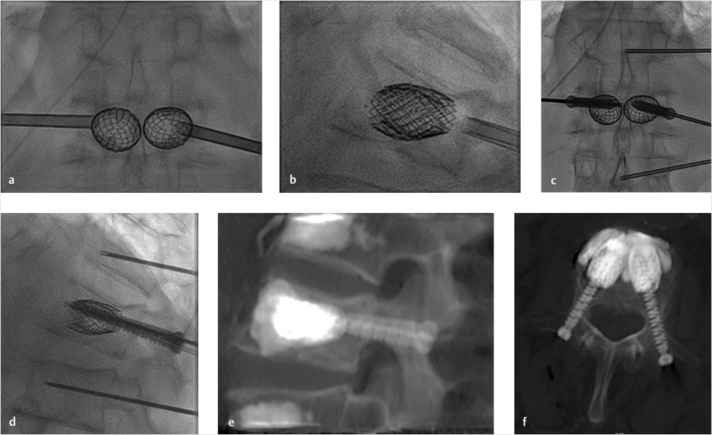
We have therefore implemented the VBS technique, combining the VBS implant with the insertion of percutaneous transpedicular cannulated fenestrated screws, followed by cement deposition through the screw (▶Fig. 32.5). The intent is to anchor the VBS-cement implant to the posterior elements, thereby reducing the risk of VBS mobilization, bridging middle-column and pedicular fractures, and protecting the middle column of additional fracture.
Fig. 32.5 Stent screw-assisted internal fixation (SAIF) technique. After bilateral transpedicular trocar placement at the pediculo-somatic junction, vertebral body (VB) stents are inserted into the VB and balloon-expanded (a, b). The trocars are removed by exchanging them over k-wires and percutaneous fenestrated and cannulated pedicular screws are inserted inside the stents’ lumen (c, d). A thin 14 G trocar is inserted at the adjacent levels in this case to perform prophylactic augmentation. Polymethyl methacrylate (PMMA) bone cement is then injected through the fenestrated screws inside the stents and the cement interdigitates in the cancellous bone and around the stents, as seen on post-procedure computed tomography (CT) images (e, f). The screws are fixed to the stents by the cement anchoring the stents to the posterior elements and bridging the middle column.
This SAIF technique, as opposed to the standard surgical external fixation achieved with screws and bars bypassing the index level, might represent a minimally invasive image-guided 360° nonfusion form of vertebral reconstruction and stabilization that would be viable even in patients with severe osteoporotic or neoplastic thoracolumbar vertebral fractures (▶Fig. 32.6).
32.4.1 Osteoporotic Fractures
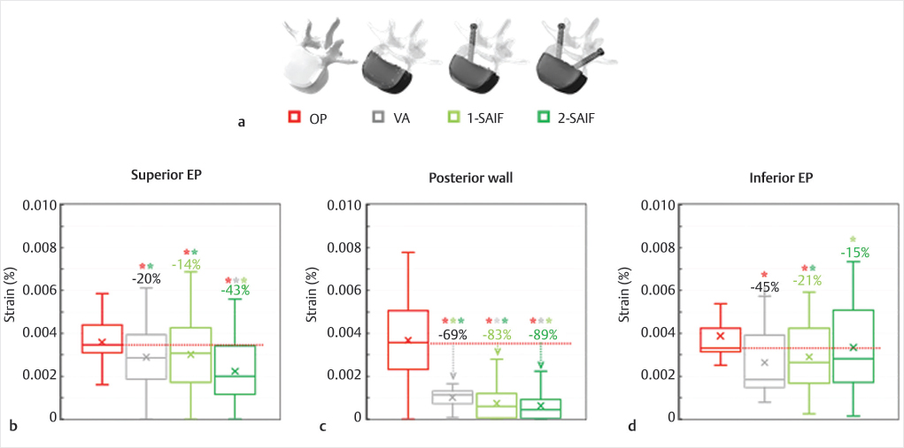
To demonstrate the biomechanical advantages of the new SAIF technique in reducing the strains (i.e., fracture risk) on the bony structures of a representative osteoporotic spine, we conducted a biomechanical finite element analysis (FEA). The previously validated intact lumbar spine model44,45 was modified to properly reflect osteoporosis46 and the VB was filled with end-plate to end-plate cement (2.5 GPa).46,47 The VB was then stressed to mimic standing and upper-body flexion.48,49 VA, unilateral SAIF (1-SAIF), and bilateral SAIF (2-SAIF) techniques were equally effective in reducing the strains on the anterior column. VA and SAIF techniques effectively reduced the strains on the treated osteoporotic vertebra (▶Fig. 32.7) but the bilateral SAIF technique was the most effective strategy to prevent the fracture risk on the superior EP and on the posterior wall, with significant reductions both over VA and 1-SAIF.
Our simulations also confirm the postoperative clinical CT images (▶Fig. 32.8), demonstrating that refracture often occur in the weak middle column (the so-called “bare area”) due to collapse and splitting. Our biomechanical analysis supports the effectiveness of SAIF technique.
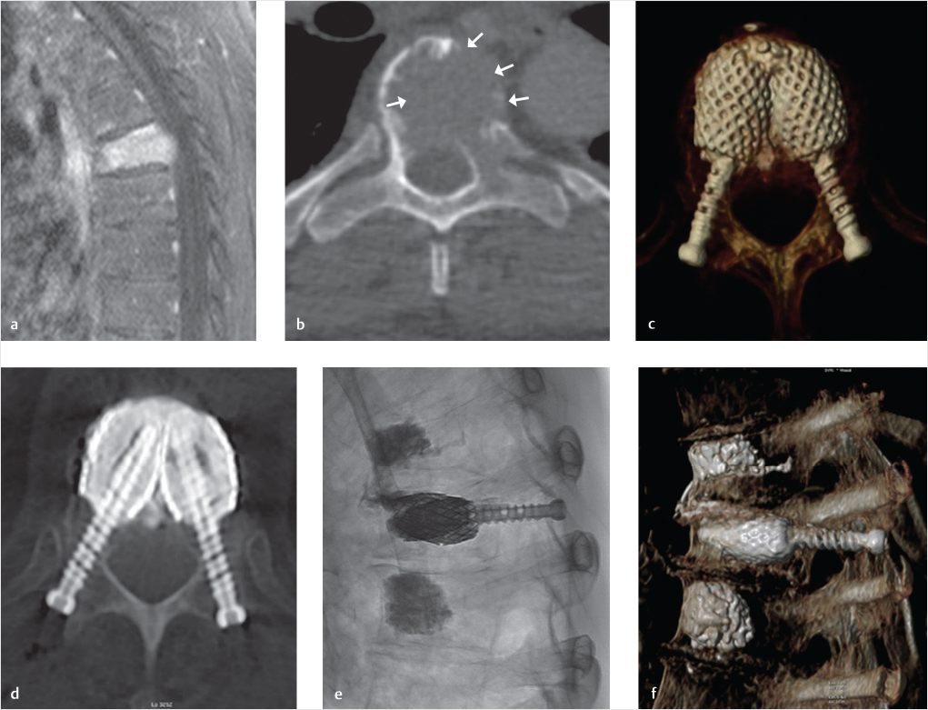
Fig. 32.6 Stent screw-assisted internal fixation (SAIF) technique in an extensively osteolytic metastasis. A T6 pathologic fracture as seen on magnetic resonance (MR) imaging with a sagittal T1-weighted image with fat saturation (a). This lesion is characterized by prominent lytic changes and wide cortical erosion as seen on axial computed tomography (CT) (white arrows in b). Standard cement augmentation would be challenging, with high risk of cement leakage and insufficient stabilization. A SAIF technique was used to reconstruct the vertebral body (VB) from within, partially restoring height, scaffolding the VB, and preventing cement leakage through the stents’ mesh. Post-procedure images (c–f) show the result of this nonfusion form of 360° internal fixation. Cement creates a bridge between the two stents and the screws anchor the cement-stent complex to the posterior elements.
32.4.2 Neoplastic Osteolysis
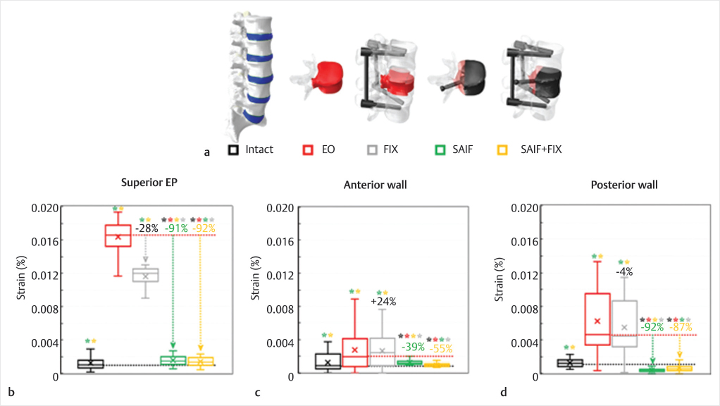
The biomechanical efficacy of SAIF technique was also investigated for the treatment of extreme osteolytic (EO) conditions by comparing this technique with standard posterior fixation.
A severe metastatic defect involving the entire L3 vertebra and one pedicle was created and described as a low-modulus region (5 MPa).50 This lesion resulted in VB instability and a complete loss of capacity of the vertebra in supporting axil compressive loads51 (▶Fig. 32.9) and an increased fracture risk with standing and upper-body flexion.48,49
The SAIF technique (SAIF) with unilateral pin insertion and optimal end-plate to end-plate filling47 with bone cement46,52 was effective in recovering the stiffness of the treated vertebra to normal values while reducing the fracture risk on the superior EP and on the posterior wall. Posterior fixation coupled to SAIF technique (SAIF+FIX) had only very minor effects in further reducing the strain on the bony structures. As a stand-alone procedure, SAIF was much more effective than conventional posterior fixation (FIX) which only shielded the vertebra from supporting excessive compressive loads and was ineffective in decreasing the bony strain (▶Fig. 32.9).
Fig. 32.7 Virtual models (a) of the osteoporotic L3 vertebra included in the biomechanical analysis: osteoporotic vertebra (OP), vertebral augmentation (VA), unilateral (1-SAIF) and bilateral (2-SAIF) screw-assisted internal fixation. The anterior two-thirds of the vertebral body (VB) is in shaded white, while screws and bone cement are depicted in black. Strain distributions on the superior end plate (b), on the posterior cortical wall (c) and on the inferior end plate (d) of the middle column of L3 during simulated upper body bending. The median percentage values refer to OP model, while statistically significant differences on median values based on Wilcoxon paired-samples test are indicated (*).

Fig. 32.8 Postoperative computed tomography (CT) images (sagittal slices) taken on lumbar vertebrae treated using vertebral augmentation (VA) and 2-SAIF (stent screw-assisted internal fixation). (This image is provided courtesy of A.C.) VA case (a): the treated vertebra refractured with splitting of the anterior and middle column. A continuous fracture spreads from the superior to the inferi- or end plates (red arrows in a) with posterior cortical wall retropulsion (yellow arrows in a). 2-SAIF case (b): the treated vertebra was found to have a new fracture involving a collapse of the superior and inferior end plate and the posterior wall as well (red arrows in b). In this case the fractured middle column does not split and there is less kyphotic deformity and posterior wall retropulsion. The principal strains’ color maps calculated for standing simulations highlighted the strain intensification effect occurring on the superior and inferior end plates of each case. A correlation between these high-tensile strain regions and the fractured bony structures could be inferred.
Fig. 32.9 Virtual scenarios (a) simulated in the biomechanical analysis modifying an intact L1–L5 model48,52: only the modified L3 vertebra is represented for the extreme osteolytic (EO) and stent screw-assisted internal fixation (SAIF) models, while only the L2–L4 segments are depicted for SAIF+conventional posterior fixation (FIX) and FIX scenarios. The metastasis and the injected bone cement are depicted in red and black, respectively. Strain distributions on the superior EP (b), on the anterior (c) and posterior (d) cortical walls of L3 due to simulated upper body bending. The median percentage values refer to the EO model, while statistically significant differences on median values based on Wilcoxon paired-samples test are indicated (*).
32.5 Conclusion
SAIF can be performed as a stand-alone procedure or be combined with surgical posterior stabilization, potentially obviating the need for corpectomy and grafting or other invasive surgical procedures on the anterior column.
The SAIF technique remains a percutaneous minimally invasive image-guided procedure but ensures effective VB reconstruction via an internal VB prosthesis that allows a 360° nonfusion stabilization. This technique may be used in fractures in which height restoration, kyphosis correction, VB reconstruction, and middle-column protection are clinical concerns.
References
[1] Maestretti G, Sutter P, Monnard E, et al. A prospective study of percutaneous balloon kyphoplasty with calcium phosphate cement in traumatic vertebral fractures: 10-year results. Eur Spine J 2014;23(6):1354–1360
[2] Evans AJ, Kip KE, Brinjikji W, et al. Randomized controlled trial of vertebroplasty versus kyphoplasty in the treatment of vertebral compression fractures. J Neurointerv Surg 2016;8(7):756–763
[3] Berenson J, Pflugmacher R, Jarzem P, et al; Cancer Patient Fracture Evaluation (CAFE) Investigators. Balloon kyphoplasty versus non-surgical fracture management for treatment of painful vertebral body compression fractures in patients with cancer: a multicentre, randomised controlled trial. Lancet Oncol 2011;12(3):225–235
[4] Ensrud KE, Schousboe JT. Clinical practice: vertebral fractures. N Engl J Med 2011;364(17):1634–1642
[5] Denis F. The three column spine and its significance in the classification of acute thoracolumbar spinal injuries. Spine 1983;8(8):817–831
[6] Genant HK, Wu CY, van Kuijk C, Nevitt MC. Vertebral fracture assessment using a semiquantitative technique. J Bone Miner Res 1993;8(9):1137–1148
[7] McCormack T, Karaikovic E, Gaines RW. The load sharing classification of spine fractures. Spine 1994;19(15):1741–1744
[8] Nevitt MC, Cummings SR, Stone KL, et al. Risk factors for a first-incident radiographic vertebral fracture in women > or = 65 years of age: the study of osteoporotic fractures. J Bone Miner Res 2005;20(1):131–140
[9] Melton LJ III, Riggs BL, Keaveny TM, et al. Relation of vertebral deformities to bone density, structure, and strength. J Bone Miner Res 2010;25(9): 1922–1930
[10] Kim YC, Kim YH, Ha KY. Pathomechanism of intravertebral clefts in osteoporotic compression fractures of the spine. Spine J 2014;14(4):659–666
[11] Ottardi C, La Barbera L, Pietrogrande L, Villa T. Vertebroplasty and kyphoplasty for the treatment of thoracic fractures in osteoporotic patients: a finite element comparative analysis. J Appl Biomater Funct Mater 2016;14(2): e197–e204
[12] Filippiadis DK, Marcia S, Masala S, Deschamps F, Kelekis A. Percutaneous vertebroplasty and kyphoplasty: current status, new developments and old controversies. Cardiovasc Intervent Radiol 2017;40(12):1815–1823
[13] Fribourg D, Tang C, Sra P, Delamarter R, Bae H. Incidence of subsequent vertebral fracture after kyphoplasty. Spine 2004;29(20):2270–2276, discussion 2277
[14] Lindsay R, Silverman SL, Cooper C, et al. Risk of new vertebral fracture in the year following a fracture. JAMA 2001;285(3):320–323
[15] Villarraga ML, Bellezza AJ, Harrigan TP, Cripton PA, Kurtz SM, Edidin AA. The biomechanical effects of kyphoplasty on treated and adjacent nontreated vertebral bodies. J Spinal Disord Tech 2005;18(1):84–91
[16] Molloy S, Riley LH III, Belkoff SM. Effect of cement volume and placement on mechanical-property restoration resulting from vertebroplasty. AJNR Am J Neuroradiol 2005;26(2):401–404
[17] Uppin AA, Hirsch JA, Centenera LV, Pfiefer BA, Pazianos AG, Choi IS. Occurrence of new vertebral body fracture after percutaneous vertebroplasty in patients with osteoporosis. Radiology 2003;226(1):119–124
[18] Nagaraja S, Awada HK, Dreher ML, Bouck JT, Gupta S. Effects of vertebroplasty on endplate subsidence in elderly female spines. J Neurosurg Spine 2015;22(3):273–282
[19] Gan, et al. Balloon kyphoplasty for OP spinal fractures with middle column compromise. Injury 2014
[20] Abudou M, Chen X, Kong X, Wu T. Surgical versus non-surgical treatment for thoracolumbar burst fractures without neurological deficit. Cochrane Database Syst Rev 2013;6(6):CD005079
[21] Gonschorek O, Hauck S, Weiß T, Bühren V. Percutaneous vertebral augmentation in fragility fractures: indications and limitations. Eur J Trauma Emerg Surg 2017;43(1):9–17
[22] Winkler EA, Yue JK, Birk H, et al. Perioperative morbidity and mortality after lumbar trauma in the elderly. Neurosurg Focus 2015;39(4):E2
[23] Han KS, Rohlmann A, Zander T, Taylor WR. Lumbar spinal loads vary with body height and weight. Med Eng Phys 2013;35(7):969–977
[24] Cholewicki J, McGill SM. Mechanical stability of the in vivo lumbar spine: implications for injury and chronic low back pain. Clin Biomech (Bristol, Avon) 1996;11(1):1–15
[25] Eyheremendy EP, De Luca SE, Sanabria E. Percutaneous pediculoplasty in osteoporotic compression fractures. J Vasc Interv Radiol 2004;15(8):869–874
[26] Provenzano MJ, Murphy KP, Riley LH III. Bone cements: review of their physiochemical and biochemical properties in percutaneous vertebroplasty. AJNR Am J Neuroradiol 2004;25(7):1286–1290
[27] Coleman RE. Clinical features of metastatic bone disease and risk of skeletal morbidity. Clin Cancer Res 2006;12(20 Pt 2):6243s–6249s
[28] Moussazadeh N, Rubin DG, McLaughlin L, Lis E, Bilsky MH, Laufer I. Short-segment percutaneous pedicle screw fixation with cement augmentation for tumor-induced spinal instability. Spine J 2015;15(7):1609–1617
[29] Laufer I, Sciubba DM, Madera M, et al. Surgical management of metastatic spinal tumors. Cancer Contr 2012;19(2):122–128
[30] Yang Z, Yang Y, Zhang Y, et al. Minimal access versus open spinal surgery in treating painful spine metastasis: a systematic review. World J Surg Oncol 2015;13:68
[31] Yu W, Liang D, Jiang X, Yao Z, Qiu T, Ye L. Efficacy and safety of the target puncture technique for treatment of osteoporotic vertebral compression fractures with intravertebral clefts. J Neurointerv Surg 2017;9(11):1113–1117
[32] van der Linden E, Kroft LJ, Dijkstra PD. Treatment of vertebral tumor with posterior wall defect using image-guided radiofrequency ablation combined with vertebroplasty: preliminary results in 12 patients. J Vasc Interv Radiol 2007;18(6):741–747
[33] Chandra RV, Meyers PM, Hirsch JA, et al; Society of NeuroInterventional Surgery. Vertebral augmentation: report of the Standards and Guidelines Committee of the Society of NeuroInterventional Surgery. J Neurointerv Surg 2014;6(1):7–15
[34] Cianfoni A, Distefano D, Isalberti M, et al. J NeuroIntervent Surg :Epub ahead of print: [Dec 2018]
[35] Muto M, Greco B, Setola F, Vassallo P, Ambrosanio G, Guarnieri G. Vertebral body stenting system for the treatment of osteoporotic vertebral compression fracture: follow-up at 12 months in 20 cases. Neuroradiol J 2011;24(4):610–619
[36] Klezl Z, Majeed H, Bommireddy R, John J. Early results after vertebral body stenting for fractures of the anterior column of the thoracolumbar spine. Injury 2011;42(10):1038–1042
[37] Thaler M, Lechner R, Nogler M, Gstöttner M, Bach C. Surgical procedure and initial radiographic results of a new augmentation technique for vertebral compression fractures. Eur Spine J 2013;22(7):1608–1616
[38] Rotter R, Martin H, Fuerderer S, et al. Vertebral body stenting: a new method for vertebral augmentation versus kyphoplasty. Eur Spine J 2010;19(6): 916–923
[39] Hartmann F, Griese M, Dietz SO, et al. Two-year results of VB stenting for the treatment of traumatic incomplete burst fractures. Minim Invasive Ther Allied Technol 2014;(9):1–6
[40] Diel P, Röder C, Perler G, et al. Radiographic and safety details of vertebral body stenting: results from a multicenter chart review. BMC Musculoskelet Disord 2013;14:233
[41] Werner CM, Osterhoff G, Schlickeiser J, et al. Vertebral body stenting versus kyphoplasty for the treatment of osteoporotic vertebral compression fractures: a randomized trial. J Bone Joint Surg Am 2013;95(7):577–584
[42] Mavrogenis AF, Papadopoulos EC, Starantzis K, Korres DS, Papagelopoulos PJ. Posterior decompression and stabilization, and surgical vertebroplasty with the vertebral body stenting for metastatic vertebral and epidural cauda equina compression. J Surg Oncol 2010;101(3):253–258
[43] Cianfoni A, Distefano D, Pravatà E, et al. Vertebral body stent augmentation to reconstruct the anterior column in neoplastic extreme osteolysis. J NeuroIntervent Surg :Epub ahead of print: [Aug 2018]
[44] Ottardi C, Galbusera F, Luca A, et al. Finite element analysis of the lumbar destabilization following pedicle subtraction osteotomy. Med Eng Phys 2016;38(5):506–509
[45] Luca A, Ottardi C, Sasso M, et al. Instrumentation failure following pedicle subtraction osteotomy: the role of rod material, diameter, and multi-rod constructs. Eur Spine J 2017;26(3):764–770
[46] Chae SW, Kang HD, Lee MK, Lee TS, Park JY. The effect of vertebral material description during vertebroplasty. Proc Inst Mech Eng H 2010;224(1): 87–95
[47] Chevalier Y, Pahr D, Charlebois M, Heini P, Schneider E, Zysset P. Cement distribution, volume, and compliance in vertebroplasty: some answers from an anatomy-based nonlinear finite element study. Spine 2008;33(16): 1722–1730
[48] La Barbera L, Galbusera F, Wilke H-J, Villa T. Preclinical evaluation of posterior spine stabilization devices: can the current standards represent basic everyday life activities? Eur Spine J 2016;25(9):2909–2918
[49] La Barbera L, Galbusera F, Wilke HJ, Villa T. Preclinical evaluation of posterior spine stabilization devices: can we compare in vitro and in vivo loads on the instrumentation? Eur Spine J 2017;26(1):200–209
[50] Whyne CM, Hu SS, Lotz JC. Parametric finite element analysis of vertebral bodies affected by tumors. J Biomech 2001;34(10):1317–1324
[51] Groenen KHJ, Janssen D, van der Linden YM, et al. Inducing targeted failure in cadaveric testing of 3-segment spinal units with and without simulated metastases. Med Eng Phys 2018;51:104–110
[52] Hansen D, Jensen JS. Mixing does not improve mechanical properties of all bone cements. Manual and centrifugation-vacuum mixing compared for 10 cement brands. Acta Orthop Scand 1992;63(1):13–18