FIG 11:1 Using an hydrometer to check the specific gravity of battery electrolyte
11:4 Testing charging circuit and regulator
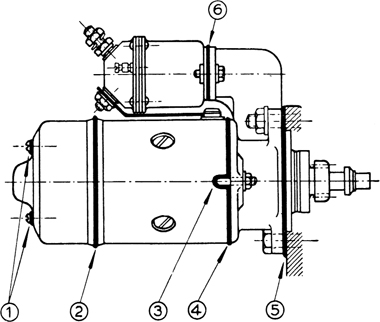
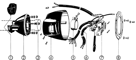
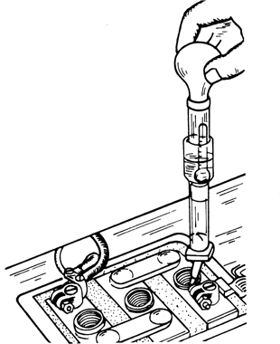
11:6 Removing and overhauling the starter
11:10 Control and adjustment of horns
11:11 Headlamp relay and flasher unit
Although the majority of the models under review have 6-volt systems, it was optional for a 12-volt system to be fitted to later cars. The increase in voltage makes very little difference to servicing instructions for the electrical equipment. There have been small changes in design over the years, but we do not think a reasonably skilful owner will have any difficulty in following the instructions in this chapter. He must, of course, provide himself with accurate moving-coil instruments for testing purposes and there are wiring diagrams in Technical Data at the end of this manual to help him with circuitry problems.
The negative side of the battery is earthed. Generator output is controlled by a regulator so that the battery is charged at the correct rate according to its condition. The regulator also contains a cut-out which disconnects the battery from the generator when engine speed has fallen so low that there is little output and the battery could discharge through the generator. With rising speed and output, the cut-out points close to complete the charging circuit to the battery.
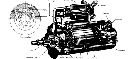
The starter motor is mounted on the transmission casing. Its shaft carries a sliding pinion that is moved into mesh with the flywheel ring gear by a solenoid and lever which are actuated as soon as current is supplied. This is shown in FIG 11:8. When the pinion is fully engaged, the starter circuit is completed and the motor will spin the engine. When the engine fires, an over-running clutch prevents the pinion from being driven by the ring gear.
Two types of headlamp have been fitted, the first with renewable bulbs and the second with sealed-beam units. Flashers, stoplights and a reversing lamp are fitted. On 356C cars the windscreen wiper motor has a variable speed control.
Some electrical maintenance and adjustment is relatively simple but it is sensible to use the maker’s exchange system when components are obviously seriously worn or defective. The regulator can be tested for output but adjustment should be entrusted to an official service station. When renewing wiring cables it is important to use the same weight of wire. This is particularly important on the 6-volt system because heavier current is passed at that voltage and thin wire might overheat and cause fires.
Every 3000 miles, check the generator driving belt for tension. If adjustment is necessary, refer to the instructions in Section 1:2 of the Engine chapter.
At every 3000 miles, check the condition of the battery and top up with distilled water as described in Section 11:3. Check all electrical components such as starter, generator and lights. Check the cables and connections for faults and loose nuts.
Every 6000 miles, slide back the covers of the generator and starter motor and check the condition of the commutators and brushes. Service them as instructed in Sections 11:5 and 11:6. The bearings do not require routine maintenance, and lubrication is confined to the application of the maker’s special grease at every major overhaul. Do not use ordinary chassis grease but only the high-temperature grease which is specified. At the same overhaul, use grease for the starter shaft bush in the transmission casing.
Heavy demands are made upon a battery, particularly when starting a cold engine, and it is most important to keep the battery top and the terminals clean and dry. Scrape away all corrosion and wipe off spilled electrolyte, neutralizing it with baking soda solution if necessary. Scrape the terminal mating surfaces until they are bright. Poor contact at this point is a common cause of starting troubles. Coat terminals with petroleum jelly to prevent further corrosion.
Topping up:
Electrolyte level drops due to evaporation. This must be restored by the addition of distilled water only. Do not use tap water. Never add acid and do not top up with electrolyte unless some has been lost by spilling.
The correct level for the electrolyte is 10 to 15 mm (⅜ to ⅝ inch) above the plates.
State of charge:
This is tested with an hydrometer, as shown in FIG 11:1. Electrolyte is sucked into the tube and the specific gravity read from a graduated float. When a battery is fully charged the reading should be 1.285. When half charged it will fall to 1.230 and it will be 1.142 when fully discharged. If the battery is not defective it may be restored by taking the car for a long daylight run or by having it recharged. A battery which is left discharged will be ruined by sulphation. If left for long periods, a good battery can be kept in condition by giving it a freshening charge every six weeks.
Instrument tests of a battery are not effective unless the heavy-discharge type is used. This is garage equipment and will test a battery under load so that faulty cells can be quickly traced.
Electrolyte:
This is a dilute solution of distilled water and sulphuric acid. If it is necessary to prepare fresh electrolyte, add the acid very slowly to the distilled water. Never add water to acid as this operation is highly dangerous. The specific gravity must be 1.285 when the electrolyte has cooled.
Charging:
When removed from the car for charging, the battery must have the filler plugs taken out. Do not charge at a rate higher than 10 per cent of battery capacity. If the battery is rated at 84 amp/hr, the charging rate will thus be 8.4 amp. The gas given off when a battery is being charged is highly inflammable, so keep naked lights away.
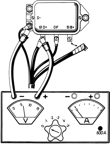
FIG 11:2 Connections for a no-load test on generator voltage output. At nominal rev/min, voltmeter should record 6 volts
When work is being done on the electrical system of the car, always remove the lead from the negative battery terminal. This will avoid the risk of shortcircuits. When refitting battery cables, connect the positive lead first.
Although the generator indicator lamp may go out as engine speed increases this does not guarantee that the battery is being properly charged. Battery trouble may be indicated by failure of the starter motor to turn briskly, by dim headlights when starting, or by the frequent need to top up the battery electrolyte. The following simple tests can be done without removing the generator or the regulator cover, but always check the condition and tension of the driving belt first. Generator rev/min are 1.8 times engine rev/min.
Preliminary tests:
1 Switch on ignition and check that generator indicator lamp goes on. Refer to FIG 11:2 for terminal identification on the regulator.
2 Disconnect generator lead from terminal 61 D+ and the lamp should go out. If it does not, the lead is earthed and must be renewed. Reconnect lead.
3 Disconnect battery lead from terminal 51 B+ as shown, and insulate the metal tag. Connect positive lead of voltmeter to 61 D+ and negative lead to an earth on the regulator base plate.
4 Start engine and slowly increase speed to nominal voltage rev/min. This is 1450 for early 160-watt generator type LJ/GE/160/6 and 1750 for the 200-watt generator type LJ/GEG/200/6. On 12-volt systems the speed should be 1850 rev/min. Voltmeter should read 6-volt (or 12-volt according to system). If no reading, generator is not charging and it must be overhauled.
5 If it is possible to use another regulator for a quick check it is wise to check the resistance of the generator field coils first to avoid damage. With regulator connected, join an ammeter to terminals 51 B+ and DF. A reading much above 5 amp indicates a short in the field coils or that they are earthed.
6 Note in all these tests that cables to the generator and regulator must not be connected or disconnected with the engine running.
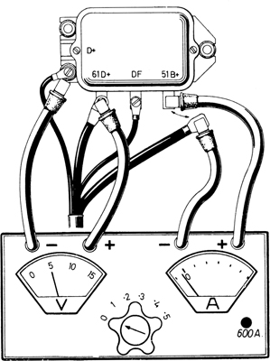
FIG 11:3 Checking that cut-out points open as engine speed falls. Ammeter indicates small negative reading, but should record zero when engine speed drops to idling
No-load voltage test:
Connect leads as in FIG 11:2, start engine and run generator up to a speed of 3500 to 4000 rev/min. Meter should register a no-load voltage of 7 to 7.5 volts. On 12-volt systems it should be approximately 14 volts. Complete these tests quickly so that the field coils are not overloaded.
Voltage test under load:
Connect voltmeter as in FIG 11:2. Connect ammeter across the now vacant terminal 51 B+ and an earth on the regulator base plate. Start engine and run generator up to speed. With cold generator, speed should be 2450 rev/min for the early 160-watt model, 2500 for the 200-watt model and 2550 for the 12-volt generator. Add 100 rev/min if the generator is warm. The regulator cover must always be in place during these tests.
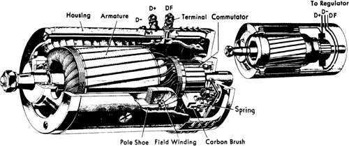
FIG 11:4 Sectioned view of a typical generator. The inset (top right) shows the internal connections from the terminals
Using the variable resistance indicated in the centre of the panel, increase resistance until the ammeter indicates 26 amp on 160-watt generator or 36 amp on 200-watt generator. Figures are not available for the 12-volt system, but will probably be in the region of 10 amp. If a separate variable resistor must be used, fit one with a range of from 0 to 5 ohm which will be able to carry at least 300 watts. Connect it between the negative ammeter terminal and earth. During this test the voltage indicated must be at least 6 (or 12) for a generator in good working order.
If the generator fails to produce current during this test, remove it and check for shorts in the field coil or armature windings (see Section 11:5). If current values are below the required figures, the regulator is at fault. Renew it or have it tested and adjusted at a service station.
Testing current:
Use the ammeter shunt so that the meter will be capable of covering the range from 100 to 600 amp. Use heavy cables for the connections. Proceed as follows:
1 Disconnect battery earthing strap. Connect negative lead of ammeter to vacant battery terminal and positive lead to battery earthing strap.
2 With all accessories switched off the ammeter should read zero. An indication of current passing will be caused by a leak to earth which must be traced.
3 Switch on ignition. Ammeter should record not more than 3 amp (less for 12-volt system). The contact breaker points must be closed for this test. A greater reading indicates defective ignition system or ignition switch.
4 Accessories may be checked in the same way by switching them on individually. Permissible current reading is accessory wattage divided by system voltage. Total current should not exceed current rating of generator.
Testing regulator for current:
Connect the meter as described in ’Voltage test under load’. Run the engine at the test rev/min and gradually reduce the value of the circuit resistance by using the variable resistance. The ammeter reading will increase until the current regulator starts to operate. This unit is the central one in the regulator. A further reduction in resistance will cause the voltage to fall sharply without affecting the amperage reading. The current regulator should cut in at 40 to 44 amp (cold) on the 160-watt generator and 37 to 41 amp when hot. On the 200-watt generator the amperage will be 50 to 54 (cold) and 47 to 51 (hot). Figures for the 12-volt system are 24.5 to 28.5 (cold) and 22 to 26 (hot).
If the current does not stay within these prescribed limits, the regulator needs renewal or adjustment at a service station.
Cut-out closing:
The cut-out unit is on the right in the regulator. To test its operation, see that the battery is in good condition and at least half-charged (specific gravity 1.230). Connect meter as in previous test, reset variable resistor to nominal output and check ammeter setting as described in that test. Proceed as follows:
1 Start engine and slowly increase speed. Voltage should increase but no amperage should be indicated. In this situation the cut-out contacts are open.
2 At increasing engine speed the contacts will close, the voltage will drop slightly and the ammeter will start to register.
3 Let the engine speed drop to idling. The voltage reading just before the needle drops back, which is when the contacts open, indicates the closing voltage. Reading should lie between 6.3 and 6.7 volts for 6-volt systems. Corresponding figures for 12-volt systems are 12.7 to 13.4 volts.
4 If the reading is outside these limits the regulator must be adjusted by a service station.
Cut-out opening:
1 Set variable resistance to zero. Connect instruments to regulator as shown in FIG 11:3.
2 Increase engine speed until ammeter shows some charging current. Gradually decrease speed and watch ammeter needle. It will fall slightly below, and then flick back to zero.
3 The maximum reading of the ammeter below the zero mark indicates the current required to open the cutout contacts. For 160-watt generators the figure should lie between 4.5 and 8.5 amp. For 200-watt generators the reading should be 4 to 9 amp. On 12-volt systems use the same figures as those for 160-watt generators.
4 If the contacts open while the ammeter shows a positive reading, the cut-out windings are shorted and the regulator must be renewed. Engine idling speed should preferably be set so that ammeter shows zero at normal running temperature. If the ammeter does not return to zero before the engine stops, the cut-out points may be sticking together and the battery will discharge through the generator. The regulator will then need renewal or servicing.
Removing and refitting regulator:
Removal is a simple matter of disconnecting the leads and removing the mounting screws. When installing, first check that the field coils are not earthed (see Section 11:5). Connect the regulator leads and polarize the generator as described in the same Section.
If readings are still incorrect after fitting a new regulator, the generator and wiring will need checking.
The brushes:
Every 6000 miles, check the generator brushes, springs and commutator. Refer to FIG 11:4 and remove the cover from the rear end. Use a wire hook to lift each brush spring in turn and pull on the brush leads to check that the brushes are free in their guides. Renew brushes which are oil-soaked, or worn until they are well below the top of the guides. While the brushes are out of the guides, use a petrol-soaked rag and a piece of stick to clean the commutator. If it is rough or worn, the commutator must be cleaned up in a lathe as described later.
Hook a sensitive spring balance under each spring and check the tension in the normal working position. It should be 16 to 21 oz and weak springs should be renewed.
When fitting new brushes, the contact face must be made to fit the curvature of the commutator by means of a strip of fine emery- or glasspaper (not cloth). Wrap the strip, face outwards, round the commutator and fit the new brush. Draw the strip to and fro under the brush until the required curvature has been produced. Wipe away all dust with a petrol-soaked rag. All solvents must be dried off before operating the generator.
Removing and refitting generator:
1 Disconnect battery. Take off outer pulley flange to release driving belt. Remove generator mounting strap (see FIG 11:5).
2 Release generator bracket from crankcase (two bolts and two nuts).
3 At the front end of the generator, remove the four screws from the fan housing cover. Lift away the generator.
Refitting:
Make sure the gasket under the bracket is in good condition and refit the parts in the reverse order to dismantling. Connect the cables according to the wiring diagram.
Before fitting the driving belt it is advisable to polarize the generator. This will prevent possible damage to the regulator and ensure proper charging. Connect the heavy red battery cable to terminal 61 D+ on the regulator. The generator should run as a motor in the direction of engine rotation. Remove the battery cable and fit the belt, tensioning it according to the instructions in Section 1:2 of the Engine chapter.
Dismantling generator:
Remove the fan by following the instructions in Section 4:5 in Chapter 4. Remove the pulley flange, using a puller if tight. With end cover removed so that brushes can be seen, disconnect the terminal lead from the positive brush holder. Remove the long bolts securing the end covers. Check that the pulley and fan keys have been prised out of the armature shaft, remove any burrs and then pull off the brush cover or end plate. Pull off the cover at the other end and the armature will come away with it. If necessary, press the cover off the armature shaft, making a careful note of position of any washers. Wash the bearings in solvent and check them for wear when dry. Clean all other parts but do not get solvent on the field and armature windings. Dry with compressed air.
The bearings are a press fit in the covers. Before refitting bearings, pack them with high-melting point grease.
Testing armature:
Burnt spots between commutator segments usually indicate broken windings. The best way of testing for these is to use a ’growler’ which is equipment normally found in a service station.
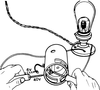
To test for earthed windings, use a 40-volt test lamp and put the prods on the iron core of the armature and on each commutator segment in turn
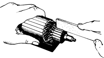
If the commutator is rough or worn, set the armature and shaft in a lathe and take very light cuts with a keen tool. Polish with fine glasspaper. Do not use emery-cloth. After this, undercut the insulation between the copper segments, using a hacksaw blade ground on the sides until it is the correct width. When cut, the insulation should be .30 to .50 mm (.012 to .020 inch) below the surface of the copper. The operation is shown in FIG 11:6.
Testing field coils:
Test for broken windings using a 6-volt lamp and battery. The connections are shown in FIG 11:7. Note dotted position of prod going to lead. If lamp does not light the field coil is faulty.
Test for internal shortcircuits by using an ohmmeter. Resistance of field coil should be 1.2 to 1.3 ohms (160-watt generator), 1.0 to 1.1 ohms (200-watt generator) and 4.8 to 5.3 ohms (12-volt generator). The same test can be made using a 6-volt battery and an ammeter. Connect these in series with each field coil to compare current flow. If the difference is more than .5 amp the coil with the higher reading is faulty.
FIG 11:7 Testing generator field coils for earthing to housing using 40-volt lamp and battery. Dotted position for prod shows 6-volt test for break in field coils
Test for earthing by using a 40-volt lamp as shown in FIG 11:7. Connect one prod to the field coil connector and the other to the generator housing (the dotted position of the prod is 6-volt testing for broken windings). The lamp should not light.
Use the 6-volt test lamp to check that the field coil windings and connections are sound. Faulty windings may be renewed by a service station.
Reassembling generator:
Press front end cover onto armature shaft and fit into housing. With brushes out of holders, fit pulley-end cover. Tighten through-bolts. Hook up springs and fit brushes. Connect field coil terminal to brush holder. Before installing generator, motor it to ensure correct polarity. Connect terminal DF to earth, positive lead of 6-volt battery (or 12-volt if applicable) to D+ and negative battery lead to earth or D—. Let generator run as a motor for short time.
Refit fan as instructed in Section 4:5. Refit pulley flange.
The cutaway view in FIG 11:8 shows all the salient features of the starter motor and the inset is a diagram of the over-running clutch which prevents the engine driving the starter.
Removal:
1 Disconnect earthing strap from battery. From terminal 30 on the starter, disconnect the cables.
2 Disconnect cable from starter terminal 50. Remove screws securing starter motor to transmission casing and lift starter away.
Dismantling starter:
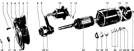
FIG 11:9 shows the components of the starter. Start by removing the solenoid 10. During major overhauls it is a good plan to renew the solenoid unit. Proceed as follows:
1 Remove nut 12 and washer 11 to release connecting strap from terminal.
2 Release solenoid unit from intermediate bracket 7 (two bolts). Pull out pinion 8 and lift solenoid away.
3 Remove end cap 15, hook up brush springs and pull brushes from holders.
4 Clamp pinion end of shaft in soft jaws in a vice and remove nut 29 from other end of shaft. Remove nuts 18 to release intermediate bracket. Pull out bracket and armature 22, making a careful note of the positions of plates, washers and shims 23 to 28.
5 Hold armature in soft vice jaws with pinion uppermost. Use a hollow drift over the shaft end to drive down the pinion stop 17 to reveal lock ring 16. Open lock ring fully so that it may be removed from shaft. Remove and discard the stop. File off any burrs on the shaft.
6 Withdraw armature from intermediate bracket and pull off pinion.
Cleaning and testing:
Do not use solvent on over-running clutch 20, on bearing bushes, nor on the windings of field coils and armature. If pinion is oily, check condition of seals for crankshaft and main drive shaft.
Key to Fig 11:9
1 Bolt
2 Lock ring
3 Pivot pin
4 Bolt
5 Pivot pin screw head
6 Lockwasher
7 Intermediate bracket
8 Pinion gear
9 Actuating lever
10 Solenoid
11 Lockwasher
12 Nut
13 Housing
14 Brush
15 Cover
16 Lock ring
17 Pinion stop
18 Nut
19 Lockwasher
20 Overruning clutch
21 Thrust washer
22 Armature
23 Spring washer
24 Holding washer
25 Thrust washer
26 Shims
27 Drive washer
28 Lockwasher
29 Nut
30 Cover screw
The solenoid unit:
Total armature travel of solenoid must be 10 ± .20 mm (.394 ± .008 inch), and 3 mm (.118 inch) of this is for contact making. To check the travel, connect a 6-volt lamp and battery across the main terminals. Push in the armature until the lamp lights and then measure the remaining travel. When installed in the starter the solenoid should pull in the armature when 4 volts are applied between terminal 30 and earth. If it does not, check for proper starter brush seating.
When installing a new solenoid unit, adjust the plunger so that the centre of the lever pivot pin in the fork is 32.4 ± .10 mm (1.275 ± .004 inch) from the solenoid flange.
Armature testing:
Check the armature as suggested for the generator armature in Section 11:5. Also use the same instructions for reconditioning the commutator if it is rough and worn. Maximum permissible runout of the commutator is .05 mm (.002 inch). Make a careful check of the soldered joints to each segment.
Field coil testing:
Broken windings may be traced using a 6-volt lamp in series with a battery. When placed across the coil ends the lamp should light. Tests for shortcircuited windings are best carried out by a service station. Earthed windings may be traced by using a 40-volt test lamp and source of current. When placed across one coil connection and the starter housing the lamp should not light.
Use a 6-volt lamp and battery to check continuity of coil connections. Defective coils must be renewed by a service station.
Brushes:
Check that brushes are not so worn that they cannot bear on the commutator. Never renew one brush only, but fit a complete set. Fit new brushes if the old ones are oil-soaked or if the flexible leads are loose or frayed.
Test spring tension in normal position, using a sensitive spring balance. Correct tension lies between 28 and 32 oz. When fitting new brushes, set the flexible leads so that they are out of the way and will not hamper brush movement.
Bearings:
Inspect bush in flywheel casing for wear. Clearance should lie between .018 and .055 mm (.0007 and .002 inch). Wear limit is .25 mm or .01 inch.
Key to Fig 11:10
1 Holes for screws in end cap
2 Rubber seal between housing and cap
3 Holes in housing for hook studs
4 Joint faces between housing and intermediate bracket
5 Joint faces between transmission housing and intermediate bracket
6 Joint faces between solenoid and intermediate bracket
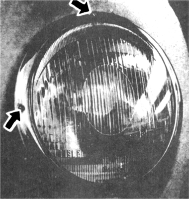
FIG 11:11 Beam setting on headlamps with renewable bulb. Top screw, vertical adjustment; side screws, horizontal adjustment
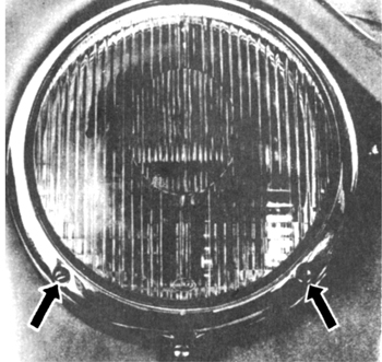
FIG 11:12 Beam setting on sealed-beam headlamps. Left screw, vertical adjustment; right screw, horizontal adjustment
If bush at commutator end is worn, fit a new one, but before pressing it into place, soak it in a bath of hot engine oil for 30 minutes. Bushes are of the porous self-lubricating type, which is the reason why they must not be cleaned with solvent such as petrol.
Reassembling starter:
Use a smear of high-temperature grease on all bearing points, on the armature brake, on the helical spline on the armature shaft, on the actuating lever and on the pinion teeth.
Reassemble in the reverse order to dismantling. After the pinion is refitted, push a new stop ring onto the shaft, followed by the lock ring and peen it with a punch. This is best done under a press, using a slotted plate for the stop ring to rest on. When completely assembled, the armature end play should not exceed .10 to .30 mm (.002 to .012 inch). Adjust by the use of shims.
It is essential to seal all joints to prevent water entering the starter. Make sure the cover seal 2 is sound (see FIG 11:10). At all the points indicated in the illustration, use sealing compound during assembling.
Refitting starter:
Before fitting the starter, check the condition of the ring gear teeth on the flywheel. If they are worn it is possible to have them refaced and rechamfered. Not more than 2 mm or  inch may be removed and the operation must be carried out accurately, so that the balance of the flywheel is not upset. After this machining it is not necessary to alter the setting of the solenoid.
Lubricate the starter shaft bush with high-temperature grease, apply sealing compound to the face of the intermediate bracket flange and to the transmission case and fit the starter. Connect generator and battery cables to upper terminal on solenoid. Connect strap to lower terminal. Reconnect earthing strap to battery. These connections must always be clean and bright as they pass heavy current.
Adjusting (renewable bulb type):
Refer to FIG 11:11 which shows the location of the adjusting screws. For vertical adjustment, turn upper screw clockwise to lower beam and anticlockwise to raise it. For horizontal adjustment, turn lower screw clockwise to move beam to the left and anticlockwise to move beam to right.
Adjusting (sealed beam type):
Refer to FIG 11:12. Turn left screw clockwise to raise beam and anticlockwise to lower it. To adjust horizontally, turn righthand screw clockwise to set beam to the left and anticlockwise to set it to the right.
Setting the beams accurately and in accordance with the regulations is best entrusted to a service station equipped with the necessary optical aiming device. Tyre pressures must be correct and the car must be normally loaded; that is, with a full tank and the driver.
Renewing bulbs:
To remove the headlamp assembly, unscrew the large screw at the lowest position on the rim. Lift out the unit. Uncouple the three-pin plug. Remove the headlamp bulb from the reflector by releasing the flanged socket. The parking light may also be removed from the reflector. To remove the reflector, refer to later instructions. When fitting new bulbs, hold them with cloth or paper to avoid smears.
Renewing sealed beam units:
This will be necessary if the reflector has become blackened with use or if either of the filaments has burned out.
Remove the lowest screw from the rim and lift out the unit. Pull off the three-pin plug. Place the unit glass downwards on a thick pad of cloth. Prise out the six spring clips from the inner ring. These clips are apt to fly, so hold one end with a finger and keep out of the way. Remove the unit from the rim. Clean the protecting glass.
To reassemble, place the locating ring on the new sealed beam unit so that it engages the three lugs. Place the two parts into the rim assembly so that the three tabs fit into the slots in the frame. Fit the spring clips so that they press against the outer ring and do not rest against the glass.
Fit the headlamp unit and three-pin plug. See that the rubber gasket is properly seated round the rim.
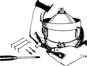
Renewing headlamp glass:
Having removed the complete unit as instructed earlier, remove both adjusting screws from the rim. Put the unit face downwards on a thick pad of cloth and remove the spring clips from the rim (see FIG 11:13). Take care that the springs do not fly. A cloth draped over the unit will help. Do not handle the polished surface of the reflector and do not try to clean it. Renew a soiled or tarnished reflector.
Reassemble by fitting the rubber gasket on the glass. Fit the glass with the shaded part at the top. Ensure that the gasket will make a watertight joint and fit the spring clips, equally spaced. Fit the unit to the car and adjust the beam setting.
Testing headlamp voltage:
If the lamps seem dim it may be due to voltage drop. Test as follows:
1 Remove unit from car (lower screw in rim). Connect a voltmeter to the low-beam terminals. Seen from the back the terminals are: left earth, top low-beam and right high-beam.
2 Switch on headlamps on low-beam and run engine at about 2000 rev/min. Voltage at terminals should be 6 to 6.3 volts (or 12 to 12.6 volts). If much less than this do the following:
3 Check battery connections. They must be clean and tight.
4 Check cable connections to regulator.
5 Check connections to light switch.
6 Check that terminals and fuses have clean contact surfaces.
7 Check the connections and contacts of the three-pin plug.
If these tests do not locate the trouble, suspect the battery, the generator or the regulator.
This is shown exploded in FIG 11:14. It combines the functions of a direction indicator switch, a low- and high-beam headlamp switch and a headlamp signal switch.
Key to Fig 11:14
1 Rubber mount
2 Base
3 Steering column
4 Housing
5 Clamp
6 Wiring
7 Switch
8 Horn contact ring
Removing:
Remove the steering wheel (see Chapter 9). Disconnect the plug connectors. Remove screws from horn contact ring 8 and remove ring. From inside housing 4, remove three nuts to release the switch, housing and cables from the steering column. Removing three screws from the side of the housing will enable the switch and cables to be pulled out from the inside. Renew faulty wiring and switch, if necessary.
Refitting:
Do this in the reverse order to dismantling. Connect the cables so that the colours match and secure them to the column with plastic adhesive tape. Before installing the horn contact ring, connect the horn wire to the back.
To reach the bulbs in the various lamps is, generally speaking, a simple matter of undoing the screws retaining the lenses. Headlamp bulbs have been covered in Section 11:7. In the case of cars fitted with separate parking lights which also house the direction indicator bulbs, grasp the lamp cover, press it in and turn it anticlockwise to reach the bulbs.
To reach the interior light bulbs, carefully pull out the complete lamp. When fitting the new bulb, check the tension of the holding clamp and be careful not to damage the retaining clips when fitting the lamp cover. Check that the three-position switch works properly.
Instrument lights:
The oil pressure and generator indicator lights are located in the face of the combined instrument. High-beam and direction indicator lights are in the face of the revolution indicator. There are two illuminiation lights for the combined instrument, the revolution indicator and the speedometer. All the bulbs for these lights are carried in sockets which are a push fit behind the instruments. When the sockets are pulled out the bulbs are removed by pressing and turning.
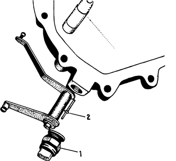
Reversing lamp switch:
This is located on the lefthand side of the transmission cover and FIG 11:15 shows the switch 1 and pushrod 2. The pushrod operates the switch when reverse is engaged.
To remove the switch, first remove the rubber cap and cable plugs. Unscrew the switch. Note that there is a locking ring on the pushrod to prevent it falling into the gearbox.
When refitting, install the pushrod with the rounded end inward, and then screw in the switch. After connecting the cables, fit the rubber cap so that it makes a watertight seal.
Door switches for interior light:
These are located in the middle of the inner hinge plate, and have only one wire attached. The switches are a push fit and may be readily levered out for attention.
The horns are located under the front wings behind the upper grille slots. Contact from the horn button is made through a carbon brush and collector ring on the steering column. Completion of the circuit actuates a relay which switches heavier current to the horns. The relay has a black cover and is located on the bulkhead under the instrument panel.
Usual horn failures are contact wear, rusty diaphragms or capacitor breakdown, but it is important to check the spring mountings. These must be installed so that the horns are free to vibrate, and do not contact the body.
Tuning:
If the horn note becomes weak or irregular, remove the mounting bolt, detach the cables and remove the horn to the workbench. Hold the end of the spring mount in a vice and connect the horn to a suitable battery. There is an adjusting screw in the back cover adjacent to the mounting. Turn this screw in or out until the note is clear and loud. If adjustment fails to give a satisfactory note, renew the horn.
Horn button:
The button can be removed by grasping the knobs on the circumference and turning it anticlockwise. Excessive sounding of the horn will be prevented if the battery is disconnected first.
The relay is fitted to pass the heavier current to the headlamps rather than through the lighter switch contacts. The device is fitted under a grey cover near the horn relay on the bulkhead under the instrument panel.
Flasher or direction indicator unit:
This is located on the bulkhead behind the instrument panel. It is a bi-metal switch with heater coil and it interrupts current at regular intervals. Failure of a direction indicator bulb should show at the warning light, but if the warning light bulb is broken, no such indication will be given and the bulb must be renewed. If the warning lamp is working, check the indicator bulbs Renew a burned-out bulb with one of the correct power or the system will not work properly.
Renewal of a defective flasher unit can be effected by simply pulling it out of its socket and pressing a new one into place.
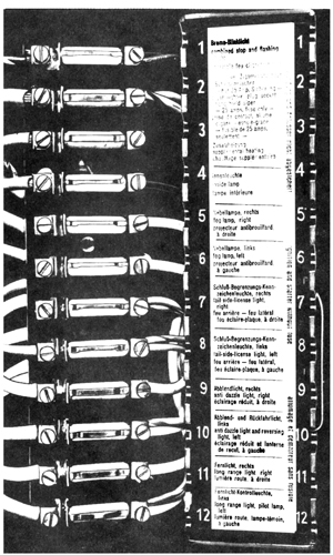
These are located centrally under the instrument panel and may be identified from FIG 11:16. Each fuse is removed by pushing downward and pulling out.
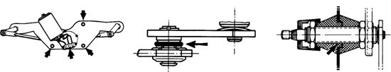
FIG 11:17 Windscreen wiper motor details. Wiring connections and mounting nuts (left), rubber washer on wiper arm crank (centre) and correct assembly of rubber caps on wiper arm bearing (right)
For 6-volt systems fit fuses as follows:
Fuse 1, 8 amp (stop and indicator lights, fuel gauge).
Fuse 2, 25 amp (plug socket, cigar lighter—windscreen wiper on some models).
Fuse 3, 25 amp (horn).
Fuse 4, 8 amp (interior light—windscreen wiper on some models).
Fuse 5, 8 amp (fog lamp).
Fuse 6, 8 amp (fog lamp).
Fuse 7, 8 amp (tail, parking and number plate lights).
Fuse 8, 8 amp (tail, parking and number plate lights).
Fuse 9, 25 amp (headlamp low beam and reversing light).
Fuse 10, 25 amp (headlamp low beam).
Fuse 11, 25 amp (headlamp high beam and indicator).
Fuse 12, 25 amp (headlamp high beam).
For these it is advisable to carry some spare 8/15 amp and 25/40 amp fuses.
For 12-volt systems, fit 8/15 amp fuses throughout.
Before fitting replacement fuses, check the circuits for the cause of failure. Each fuse is a protective device and it may indicate some electrical fault. Never fit fuses of a greater capacity and do not substitute with wire.
Until late in 1961, a single-speed wiper motor was fitted. After that date a modified variable-speed motor was fitted, the speed being controlled by turning the knob of the on-off switch.
Removing single-speed motor:
Before tackling this operation it is necessary to mention that two makes of wiper assemblies have been fitted. These are Bosch and SWF. The connecting rod joints on Bosch wipers require no servicing. On SWF wipers, the joints should be oiled at regular intervals.
To remove the motor, remove the connecting rods from the motor crank. Slacken the setscrew and remove the crank. Disconnect the cables, remove the three mounting screws and lift away the motor.
Removing variable-speed motor:
Remove the wiper arms and then the rubber sleeves, nuts, cup washers and rubber cap. Disconnect wires at snap-on connectors (see FIG 11:17—lefthand view). Remove righthand connecting rod from both ball sockets. Remove lefthand connecting rod from ball socket of wiper arm crank. Remove three nuts indicated by outer arrows in FIG 11:17 (lefthand view) and withdraw bracket and motor.
Installing variable-speed motor:
Note that the removable connecting rod must be installed on the righthand side. Fit a rubber spacer washer between the wiper arm crank and the connecting rod as shown in FIG 11:17 (central view).
Before connecting the wires, check the colour of the wire to the motor terminal with that on the motor switch terminal. This will avoid shorting the battery.
To make a watertight seal of the wiper arm mountings, fit the rubber caps in the manner shown in FIG 11:17 (righthand view). The connecting rod joints need no lubrication.
Wiper troubles:
Rattles may be cured by attention to the rubber washers fitted to the wiper arm cranks as shown in the central view of the illustration.
Check the rivets in the tension piece for the wiper arm. Tighten the rivets if necessary.
The wiper rubber must turn after each cycle. If it remains in one position, twist the arm so that the rubber is square with the screen. Set the blades so that they sweep the same pattern.
(a) Battery discharged
1 Terminal connections loose or dirty
2 Battery internally defective
3 Shortcircuits
4 Generator not charging
5 Defective regulator
(b) Insufficient charging current
1 Check 1 and 4 in (a)
2 Generator driving belt slipping
(c) Battery will not hold charge
1 Low level of electrolyte
2 Battery plates sulphated
3 Electrolyte leaking from cracked casing or top seal
4 Plate separators defective
(d) Battery overcharged
1 Regulator defective
(e) Generator output low or nil
1 Belt slipping or broken
2 Faulty regulator unit
3 Shaft bent, bearings worn, polepieces loose
4 Commutator insulation proud, segments worn, burned or shorted
5 Brushes sticking, springs broken or weak
6 Field coils faulty
(f) Warning lamp not lighting with ignition on
1 Battery discharged or faulty
2 Defective ignition switch
3 Bulb burned out
4 Generator brushes not contacting commutator
5 Loose connections or broken cables
(g) Warning lamp stays on or flashes intermittently
1 Driving belt slack, generator faulty
2 Regulator defective, cables loose or broken
(h) Warning lamp goes out only at high speed
1 Generator or regulator faulty
(i) Warning lamp stays on with ignition off
1 Contact points in regulator stuck together
(j) Starter motor lacks power or will not operate
1 Battery discharged, loose connections
2 Solenoid switch contacts worn or dirty
3 Brushes worn or sticking, springs broken or weak
4 Commutator, field coils or armature defective
5 Armature shaft bent, engine abnormally stiff
(k) Starter motor runs but does not turn engine
1 Pinion or flywheel gear defective
(l) Starter pinion stays in mesh
1 Armature shaft dirty or bent
2 Solenoid switch faulty
(m) Lamps inoperative or erratic
1 Battery low, bulbs burned out
2 Switch faulty, poor earthing, loose connections, broken cables
(n) Wiper motor does not run
1 Armature touching polepieces, windings faulty
2 Brush or commutator trouble
3 Switch or wiring faulty
(o) Wiper motor slow, squeaky operation
1 Dirty or worn brushes, pressure low
2 Tight hinges to brush holders
3 Dirty commutator
4 Armature touching polepieces
5 Linkage unlubricated