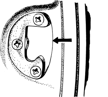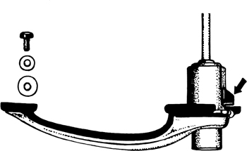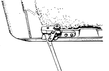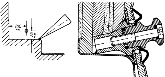
FIG 12:1 Remove four hinge bolts and use packing to adjust fit of door in body aperture
12:3 Removing, installing and adjusting doors
12:4 Servicing doors and windows
12:5 Door lock removal and installation
12:6 Removing and refitting windscreen
12:7 Removing and refitting side windows
12:9 Fresh air ventilation control
12:10 Removing and refitting pedal assembly
Synthetic enamel is used for the paintwork, but small blemishes may be eliminated with cellulose lacquer. Before attempting to spray body panels it is essential to remove all wax polish, especially if it contained silicones. White spirit will remove wax, but a special cleaner is needed for silicones. Light abrasion with very fine ’Wet or Dry’ paper will also give a suitable surface for painting.
Air-drying enamel has not the durability of paint which is dried in an oven, so use it only for small touch-up work. Remember, too, that colour changes with exposure to light, so that a small re-sprayed patch in the middle of a body panel may be only too obvious. In that case it is far better to refinish the complete panel.
Remove every trace of rust, and spray primer on bare metal. Use a putty filler on deep scratches and blemishes. Leave to dry overnight, rub smooth with grade 240 ’Wet or Dry’ abrasive paper and apply another coat of primer. When this is dry, rub down with grade 320 paper and finish off with 400 grade. Wash off all dust and dry thoroughly before applying two coats of thinned enamel. Metallic colours need an extra coat. Leave to dry for several days before polishing.
Before removing the bonnet panels, always scribe round the hinge fixings so that they can be restored to their original positions during reassembly. The same applies to lock parts. When refitting the front lock assembly, leave the bolts loose. Lower the bonnet and watch the contact of the tapered latch bolt secured to the bonnet, and the release parts of the lock. Adjust until correctly aligned and tighten lock fixings. To adjust the locking depth so that the bonnet closes the desired amount, unlock the tapered latch pin and screw it in or out as required. Apply grease to the contact surfaces.
If the front lock release cable breaks it is possible to unlock the bonnet from under the lefthand front wing. There is a rubber access plug just above the horn and it may be necessary to remove the horn to reach it comfortably. Push a length of fencing wire through the hole, and pull the lock release arm with a hook formed on the end of the wire. If the rear lock release becomes inoperative from outside, locate a rubber plug in the floor adjacent to the silencer and under the lock. Remove the plug and insert a stout steel rod upwards until the catch can be pushed sideways to disengage it.
If the rear lock is removed, leave the four screws finger tight during reassembly. Check the locking action by slowly closing the bonnet and when satisfied, tighten the screws. Grease all contact surfaces.
Removing:
Remove sheet metal covering from hinges. Remove cotters and drive hinge pins downwards. Cut a slot in a length of thick steel bar so that the fork will embrace the hinge pin and rest on the head. Hammer on the bar to extract the pin. To reach the lower hinge pin, remove the rubber plug from the sill, below the hinge. A second operator must hold the door while the pins are finally removed.
Installing:
Before refitting a door, check the condition of the sealing strip. When the hinge pins are again in place, check that the door fits flush with the body on all sides. Adjustment is made by removing the bolts arrowed in FIG 12:1 and fitting or removing shims under the hinge plate. Note the grease nipple for hinge pin lubrication. Check weather sealing by inserting a piece of paper in the jamb as the door is closed. If the paper can be pulled out easily when the door is fully closed, then the sealing strip must be renewed, or stiffened up by sticking some foam rubber strip under it. Use French chalk on the rubber strip if it squeaks.
Adjusting lock:
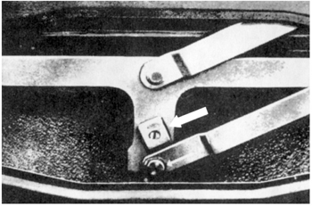
The striker plate is shown in FIG 12:2. If the door rattles or does not close properly, loosen the three crosshead screws and move the plate vertically or horizontally as required.
Removing door trim:
The door handle and window winder crank are secured to their spindles by cross-pins. These become visible if the boss surrounding each spindle is pressed inwards. Drive out the pins and pull off the handles. Remove the top moulding (two cross-head screws). Do not remove the door pull. Release the panel from the door by removing all the screws, noting that there is one inside the glove compartment.
Refitting door trim:
Check rubber strips and renew if necessary. Fit the springs to the spindles before fitting the panel.
Removing and installing window (Coupé):
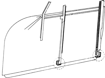
Lower window and remove trim panel. Remove rubber pad from winder spindle. Disconnect window channels from bottom of door (see FIG 12:3). The window glass is carried in an elevating track. Bend open this track at the end farthest from the winder, spread the channels and pull the glass inwards out of the frame. Tilt and lift the glass so that the front roller leaves the end of the elevating track and lift the window edgewise from the door. The winder mechanism is secured to the door by the screws shown in FIG 12:5.
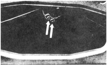
Install in the reverse order. Lower the window edgewise so that the elevating track engages the rollers of the elevating mechanism. Bend the track back into shape. When securing the channels, set them so that the window is free to slide without excessive play. Adjust window for level at pin indicated by thin arrow in FIG 12:4. The large arrow points to the stop which limits window travel.
Removing and installing window (Cabriolet-hard-top):
Repeat the operations in the preceding instructions until the channels are released from the door. Remove the nut from the inner end of the pin indicated by the white arrow in FIG 12:5. Roll the other elevating arm out of the track, pull the glass out of the frame and tilt it edgewise to remove it.
Install with the elevating mechanism secured finger tight. Fit the glass on edge so that the elevating roller engages and the window fits in the channels. Secure the lower ends of the channels. Fit the nut on the inside of pin indicated in FIG 12:4 and raise the window fully to see whether the window is parallel to the frame. Adjust at the mounting screws of the mechanism and then tighten them. Fit felt moulding at upper edge of window slot. The end stops for window travel are adjustable for upward and downward positions as shown in upper and lower views of FIG 12:6 respectively.
Removing and installing window (Roadster):
Use the preceding instructions, but work the mechanism into the flattest shape when feeding it through the lower opening in the door. The window glass must be tilted inwards so that it seals against the roof and the windscreen pillar when the door is closed. Adjust by re-positioning the window channels.
In all these operations involving the winder mechanism, apply grease to the moving parts.
Removing ventilation windows:
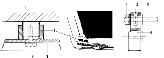
Lower window and remove trim panel. From inside door, remove nut indicated by arrow in FIG 12:7. Drill out rivet from upper hinge. Lift window upward and out. Renew weatherstrip if deteriorated.
When refitting ventilation window, adjust spring tension on friction brake at nut shown in FIG 12:7. This must be a self-locking nut.
FIG 12:4 Large arrow indicates stop on window carrier to regulate window travel. Adjust pin at thin arrow to set window level
FIG 12:5 When removing window and elevating mechanism, take out bolts indicated by arrows (top). White arrow points to pin and nut that must also be removed
Removing window frame (Coupé):
Remove bolt from rear edge of door. Use socket spanner to remove two bolts from front edge of door at the top. Remove bolt just below ventilating window catch and another a little to the front of the winder spindle. Release window channels from bottom of door and lift out assembly upwards. Renew defective seals and felt linings, then refit the frame in the reverse order.
Removing window frame (Cabriolet-hardtop):
The fixings for the ventilation window frame and front channels are much the same as those described for the Coupé window frame. To remove the rear channel take out two screws inside the door at the top edge and the two securing the bottom end of the channel.
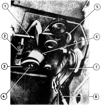
Key to Fig 12:8
1 Pushbutton plunger
2 Catch return spring
3 Latch spring
4 Pin for spring
5 Catch
6 Latch
7 Catch release and lock
8 Catch release cable
Removing window frame (Roadster):
Remove trim panel and window as previously described. Inside the door at each end of the top aperture for the glass is a single bolt. Remove these bolts and the two lower down and vertically in line, somewhat below the level of the winder mechanism. Remove the channels.
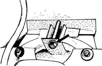
The lock mechanism can be seen in FIG 12:8 where it is shown with the door closed. The arrow on the right-hand lever shows the action when the door is locked from the inside.
Removing:
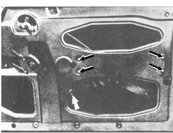
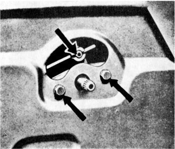
Remove trim panel and window (see Section 12:4). Remove window frame or single channel according to model. Release cable from lever by unscrewing setscrew indicated by top arrow in FIG 12:9. Door lever is detachable by removing the two bolts shown. Release lock from door by removing the four screws shown in FIG 12:10. Check the action for broken springs and worn parts and renew assembly if necessary. Grease all moving joints and sliding surfaces.
Refit the lock and control in the reverse order. Adjust the position of the striker plate on the door pillar as explained in Section 12:3.
Exterior handles for door locks:
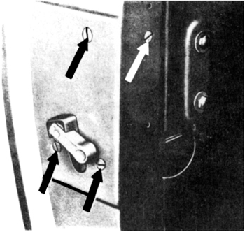
The handle and fixing is shown in FIG 12:11. To remove it, take off the door trim panel inside (see Section 12:4). Remove the screw from the tail of the handle, then pull the handle sideways and out until the tang which is arrowed is clear of the door.
FIG 12:9 Setscrew for door release cable (top arrow) Lower arrows point to bolts securing lever assembly
FIG 12:11 Door handle and lock assembly showing tang (arrow) which helps to retain handle in door panel
Key to Fig 12:12
1 Windscreen glass
2 Trim strip
3 Rubber strip moulding
4 Flange on body shell
When refitting the handle, make sure the rubber gaskets are in good condition. Test lock operation before fitting the trim panel. If necessary, file the end of the pushrod or adjust it by bending until the lock functions correctly.
Removing (Coupé and Cabriolet hardtop):
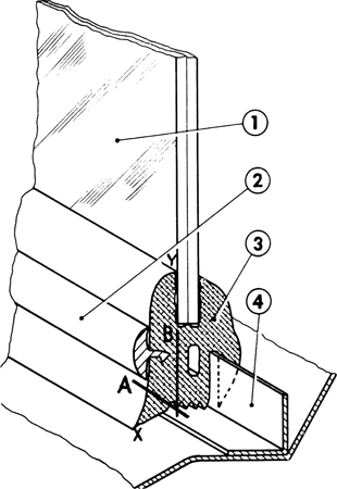
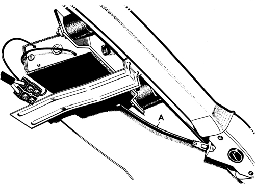
Remove the wiper arms and then take a sharp knife and cut the rubber weather strip as indicated by the line A in FIG 12:12. Take care not to damage the aluminium trim 2. The ends of this trim are joined by connectors. Slide these to one side and remove the trim by inserting a screwdriver under it and drawing the blade evenly round the screen.
On the outside, loosen the rubber from the glass and cut parallel to the glass on the line B. Be careful not to chip or scratch the glass if it is to be used again. With the palm of the hand, gently drive out the upper part of the screen from the inside until it is free and the screen can be lifted away. Clean the windscreen surround, removing all traces of sealer.
Installing (Coupé and Cabriolet hardtop):
If screen was broken, make sure all particles have been removed, particularly from the demister ducts. Fit the new rubber surround to the screen so that the join is centrally placed at the bottom. Moisten the slot with rubber lubricant or soapy water and press aluminium trim strip 2 into place. Fit the connectors to the ends and slide into place. Note the slot which fits over the body flange 4. Feed a stout cord into this slot. Overlap the ends and let them hang out of the slot at the top of the screen.
Set the screen into the body aperture, engaging the lower edge first. Press it into the frame as far as possible and then take an end of the cord and pull it down and parallel to the glass. The rubber flange will be curled out over the body flange 4. When this operation is completed, take a wooden block and a hammer and lightly tap the surround until the screen is firmly seated.
FIG 12:13 Bolt behind instrument panel which secures lower end of windscreen tensioner on Roadster models
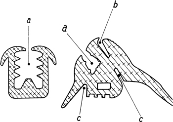
FIG 12:14 Sections through rubber strip mouldings for Roadster windscreen. Strip for top and sides (left), bottom strip (right)
Key to Fig 12:14
a Windscreen slot
b Slot for trim strip
c Slots for body sections
FIG 12:16 Drive pinion and cables for sliding roof (top), removing cables and rear guides from rails (bottom)
Sealing is the last operation Use the special rubber cement made for windscreens and inject it under the overlapping strip round the outside edge, lifting the rubber tongue with a putty knife or similar tool. Do the same with the outside joint between the rubber and the glass. These are marked as points X and Y in the illustration.
Removing windscreen (Roadster):
Lower the top and remove the wiper arms. Remove nut and rubber pad to release clamps from wiper arm shafts. Prise out trim strip by lifting upward and out. Remove central tension rod by unscrewing two screws at the top and releasing the tension at the bolt indicated by the arrow in FIG 12:13. This is located under the instrument panel.
There are two socket-head screws in the extreme left and right lower edges of the instrument panel. These screw into the windscreen uprights. Remove the screws and lift the complete screen away from the body. Remove the lower rubber strip and release the screen from its frame.
Refitting windscreen (Roadster):
If a new glass is to be fitted, compare it with the old one to make sure that it is the same shape. Any differences must be corrected by reworking the glass. Fit the rubber strip (left in FIG 12:14). Push the assembly into the frame and hold in place with two loops of cord. Fit the lower rubber strip. A section through this is shown in FIG 12:14 (right). Fit assembly to car. Tighten socket-head screws. Check fit of screen with respect to door and fabric top. Space should be an even 15 mm (⅝ inch), and errors may be corrected by fitting shims under the windscreen pillars. Refit the central tension rod.
Lift the lip of the lower rubber strip to check that the body section is properly engaged. Press down on the rubber until it is fully seated. Fit a cord in slot ’b’ and insert trim strip. Pull out cord downwards and press trim into place. Fit clamps to wiper arm bearings. Test for leaks with a hose. Seal with rubber cement after drying thoroughly.
Removing and refitting rear window:
This is accomplished in a manner similar to that adopted for windscreens.
Open window and release linkage from body (three screws). Remove window by releasing hinges (two screws each). The hinge post may be detached by removing two countersunk screws from each corner and pulling the post outwards. The weather strip must be removed from the outer edge of the frame. The glass, and the rubber channels, are now readily detached.
Inspect the rubber weather strips and renew them if deterioriated. Reassemble the parts in the reverse order of dismantling, checking that the rubber strips are correctly seated and that the window opens and closes properly. It is a good plan to dust the rubber parts with french chalk after fitting.
The sliding roof is electrically operated, the motor being connected to the transmission by a flexible shaft. The transmission consists of a pinion meshing with two flexible cables and a friction clutch to prevent damage or personal injury. If the electric drive fails, remove the plastic cap centrally placed at the front and remove the slotted screw from the pinion shaft (see part 5 in FIG 12:19). Take particular care of the spacers 6. Insert the hand crank provided and turn it in the required direction.
Removing:
With lid half open, remove head lining screw in each front corner. Pull lining forward. The reinforcement for the head lining frame is secured at each end with adhesive tape. Release and withdraw the reinforcement from the head lining frame brace. Pull head lining over the roof and remove in a forward direction.
Set lid about two inches open and remove the guides after loosening the screws in each front corner. Remove screws at guides and detach shackle from bracket. Use a screwdriver as in FIG 12:15 to push the lifters off the studs and remove them. Raise front end of lid and slide it out.
Installing:
Slide the lid into place, making sure that the cable guides are within the cut-out at the back. Mount lid lifters on studs of cable guides. Secure shackle to bracket. Hook the spring which is fixed to the cover, under the studs of the lifter guide. Lid should slide smoothly without binding. If necessary, adjust cables in drive housing as described later. Adjust lifters and lids. Refit head lining and frame reinforcement. Push the reinforcement over the frame brace and secure the ends with adhesive tape.
Servicing cables:
Remove lid as just described. From centre of roof at the front, remove cover over drive housing and plate over drive pinion (see upper view, FIG 12:16). Remove connections, top and bottom, from front edge of roof opening. Remove the two guide elbows in the corners and pull out the cables and rear guides as shown in the lower view of FIG 12:16.
Check cables for wear, kinks or other faults. If one cable is faulty it is recommended that both should be renewed. New cables must not be shorter than before, but they may be slightly longer. Use a grease with molybdenum sulphide additive for lubrication.
When refitting the cables and guides, make sure that the rails and elbows are flush with each other, setting them if necessary. Insert cables in drive housing so that the righthand cable lies in front of the pinion and the left- hand cable behind it (see FIG 12:16). Fit plate and cover and check lid movement. If faulty, adjust as described later.
Removing and installing motor:
Open zipper in roof lining and disconnect wires at connector (see FIG 12:17). Withdraw flexible shaft A. Release motor from rubber mounts.
When installing, check that felt round motor is sound as this reduces noise. Fit motor, insert shaft, connect wires and check operation. Motor can be moved until action of flexible shaft is smooth.
Removing and installing transmission:
Open lid, remove cover and retaining plate from drive housing (see upper view in FIG 12:16). Remove both connections, top and bottom, from front of roof opening. Remove drive housing. Open zipper and withdraw drive shaft (see preceding instructions). Detach roof lining where necessary in order to remove transmission retaining screws and withdraw transmission.
Refit in the reverse order. Follow preceding instructions when fitting cables to drive pinion. When fitting retaining plate, make sure that the drive shaft does not lie above it. Glue roof lining back into place.
FIG 12:18 Adjusting position of sliding roof. Raise or lower roof 1 by altering nuts 2 after loosening screws 4 that secure guide 3 (lefthand and central views—front end of roof). Rear end of roof (righthand view); loosen nut 1 on stud 3, turn screw 2 to alter position of stud in lifter 4
Adjusting position of lid:
Front end, either side:
Refer to lefthand and central views of FIG 12:18. Remove lid lining and frame (see earlier notes). Alter relative positions of lever and lid by slackening screws 4. Reset locknut 2 on lid 1 and tighten screws.
Rear end, either side:
Remove lining as before. Refer to righthand view in FIG 12:18. Loosen nut 1 and turn screw 2 in desired direction until stud 3 is in correct location with lifter 4.
Correcting one-sided lift of lid:
There is a lifter ramp in the gutter of the sliding roof aperture which must be flush with the lid lifters. To correct lifting errors, open the lid and then check where each lifter contacts the ramp. The lifter should make contact in the centre of the ramp, so straighten the ramp if this is not the case. Position the ramps so that when the front edge of the cover contacts the velvet seal, the lifters are at an angle of 45 deg. If necessary, readjust the lifters as described in the instructions just preceding this one.
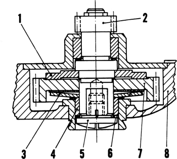
Key to Fig 12:19
1 Counter plate
2 Pinion
3 Spring pressure plate
4 Bearing bush and pressure piece
5 Screw
6 Shims
7 Gear
8 Housing
Correcting uneven travel:
Operate lid and determine which side is slow during closing. Open lid and remove drive housing cover. Remove retaining plate to expose pinion. If righthand side of lid is slow, lift forward cable over drive pinion, pull it to the left by one or more teeth and reinsert it. Check the operation and carry out further adjustments if necessary.
Checking and adjusting friction clutch:
A section through the clutch is shown in FIG 12:19. It is working properly if the motor continues to run at reduced speed when the roof has closed and the switch kept on. If the switch is operated when the roof is already closed, the motor should not operate the clutch. This, of course, only applies when the switch is moved to the ’Z’ or closed position.
To adjust the clutch, remove plastic cap from transmission. Use the crank which is provided, to remove screw 5. If clutch slips too readily, add shims 6. Spares for the car include three shims in a plastic bag. Remove shims if clutch is too tight.
Seals
There is a large velvet sealing strip glued to the front and to both sides of the roof aperture. There is a smaller velvet strip on the rear edge of the lid.
When renewing the smaller strip, note that it must be glued right to the end of the rear radius of the lid. The large velvet must be glued on so that there is no gap between the two seals. Behind the small velvet seal there is a weather strip which is glued to the rear profile of the lid by its short side. The long side will then lie under the rim of the small seal. Renewal of these two parts entails removal of the lid.
The fresh air duct is secured to the luggage compartment bulkhead by a long bolt and nut. The flaps are operated by Bowden cable. Lubricate the shafts of the flaps from time to time.
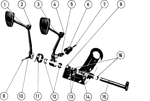
Key to Fig 12: 20
1 Clutch pedal
2 Clamp screw
3 Brake pedal
4 Clamp screw
5 Connecting link
6 Rubber boot (inverted after installation)
7 Pushrod
8 Washer
9 Roll-pin
10 Heavy roll-pin
11 Return spring
12 Bushes
13 Rubber buffers
14 Pedal bracket
15 Clutch pedal shaft
16 Shaft bushes
Setting cable control:
The cable must make a gentle bow between the ventilation control lever and the clip on the duct. Place lever in central position and secure cable housing to appropriate clip. Turn the flap control lever so that it is nearest to the cable clip and the flaps will then be closed. Secure the inner cable to the flap control lever. Check the action and adjust cable if there is tension in any position
Removing:
Remove mat and disconnect ball joint of throttle linkage from behind the accelerator pedal. Detach pedal and bracket (two bolts). Remove the toe board to gain access behind the brake and clutch pedals. The components of the assembly are shown in FIG 12:20.
FIG 12:21 Fitting anchorage points for seat belts when not fitted as standard. Reinforcement plate on left, fixing details on right
Key to Fig 12:21
1 Body panel
2 Sound-deadening compound
3 Trim
4 Reinforcement plates
5 Shackle
6 Spring washer
7 Nut
8 Hook
9 Seat belt
Disconnect clutch cable from lever on shaft 15, holding cable with pliers to prevent twisting. Disconnect master cylinder pushrod from link 5. Release pedal bracket (three bolts). Release return spring 11. Drive out roll-pins 9 and 10 from clutch lever boss. Draw clutch pedal off shaft, followed by the parts 11 and 3. Note the position of thrust washer 8. Remove shaft 1 5.
Clean and inspect for wear. Renew bushings 12 and 16 if worn. Renew rubber buffers 13 if they have deteriorated.
Refitting:
Reverse the removal sequence, greasing the shaft and bearings. Secure the clutch pedal with a new roll-pin 10 and pin 9. Check the adjustments of the clutch cable and the brake pushrod according to the instructions in Chapters 5 and 10 respectively.
Speedometer:
To remove the speedometer from the panel, reach behind and pull out the lights from the sockets. Unscrew the nut securing the cable to the back of the instrument and pull the cable clear. Remove the clamping bracket from the back of the instrument and pull the head forward away from the panel. When refitting the instrument, check that the light sockets make good contact and set the face so that the figures are correct.
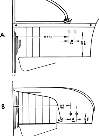
FIG 12:22 Fitting anchorage points for seat belts, when not fitted as standard. Hole positions for Coupé (A), for Cabriolet (B)
Speedometer cable:
With cable disconnected from behind instrument as just described, detach driven end of cable. First remove the lefthand front hub cap to reveal the splitpin and square end of the cable. Remove the pin and prise out the cap from the hub. Pull cable out of stub axle from the back. Remove cable from car.
When refitting the cable, take care not to stretch or kink it. All curves should be smooth ones with a radius not less than 150 mm (6 inch). With the front wheels set straight-ahead, the cable should lie in a gentle curve and must not become kinked or stretched on either wheel lock. Any kink or flattening of the outer casing will cause pulsations of the speedometer needle. Sharp bends are the most likely cause of premature failure.
There is a rubber seal round the cable inside the stub axle. It is held in place by a flared steel tube. Make sure the seal is in good condition so that water cannot enter.
Lubricate the inner cable with oil or a water-resistant grease. When connecting the cable ends, use a new splitpin at the axle end and check that the upper squared end fits into, the instrument without force. Before coupling the cable, make sure that its flanged end is flush with the speedometer housing.
Tachometer cable (revolution indicator):
Use the same care with the run of this cable as outlined in the preceding notes on the speedometer cable.
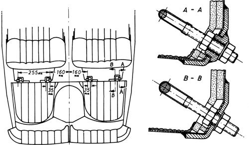
FIG 12:23 Location of anchorage points (left) and anchorages installed (right) on cars where fittings are standard. They are behind the front seats. Later models have eyebolts instead of shackles
FIG 12:24 In addition to shackles fitted as in FIG 12:23, diagonal shoulder belts require retaining bolts (right) located in rear panels as shown on the left
To remove the cable, disconnect it from behind the instrument. Remove the toeboard. Detach the cable from the drive on the engine timing cover. Release cable from clamps and withdraw it.
When installing cable, renew rubber grommet in rear panel, coating the cable and grommet with waterproofing compound. Check the condition of the rubber strap above the rear axle.
Combined instrument:
This carries the warning lights, the fuel gauge and the oil thermometer. To remove, disconnect all cables from the back, remove the nuts from the clamp, pull out the lights and pull the instrument from the front of the panel. Keep a careful note of the electrical connections so that they may be replaced correctly during reassembly.
Place a thin, but strong, cord in the groove in the rear weather strip so that there is enough at each end to provide a hand grip. Hook the two turnbuckles to the ball studs on the roof.
Two operators must now lift the hardtop into place so that the lugs in the door pillars are engaged. Secure by means of nuts and flat washers. Check fit of roof against windscreen, adjusting if necessary by shims under the lugs on the door pillars. Connect and tighten the two turnbuckles moderately.
Pull the cord to the inside so that the weather strip lies smoothly over the rear panel. Any places where the rubber does not fit properly may be corrected with a plastic blade, taking great care not to damage the finish. Tighten the mounting bolts and turnbuckles a turn at a time in sequence. Fit the covers over the turnbuckle brackets and secure them with a punch held parallel with the buckle on each side. Secure the three holding-down clamps at the windscreen.
Fit the side wall panels. If a new hardtop installation is being made it is possible that the fixing hole is covered. To locate it, fit the two tabs of the panel into the door pillar and mark round the panel with chalk. Remove the panel and measure in from the back edge 3.5 cm (1⅜ inch) and up from the bottom corner 6 cm (2⅜ inch). Locate the hole with a punch and insert the screw in the hole with the head coated with chalk. Refit the side panel and press it against the screwhead so that the chalk leaves a mark. Remove panel and punch a hole through at the mark. Remove screw, refit panel and secure with screw.
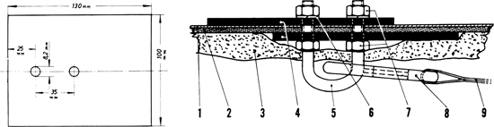
Anchorages may be fitted to 356A cars from the following serial numbers: Coupé 101.693, Cabriolet 150.001 and Speedster 83.792. For diagonal shoulder belts it will be necessary to make the reinforcing plates shown on the left in FIG 12:21, using steel plate 4 mm (.16 inch) thick. To fit the shackles as shown in FIG 12:21 (righthand view) and FIG 12:22, according to model, first remove the cover strip and/or side trim. Mark the holes as shown. Push the shackle through the covering and adjust the position of the inside nuts 7 so that the loop will project into the car about 18 mm (.70 inch). Fit a reinforcing plate 4 so that the longer part faces forward. It is not necessary to remove the sound-deadening material. Push shackle through wheel housing, coat second shackle with sealing compound and fit it with long part to the rear. Fit nuts and spring rings. If threaded ends project from nuts more than about 3 mm (⅛ inch) they may contact wheel on large deflections, so reduce length if necessary. Coat whole of installation in wheel arch with sealing compound. Refit interior trim.
Fitting seat belts to existing anchorages:
These anchorages will be found on cars from the following numbers: Coupé 120.620 and 210.931, Cabriolet 156.850. The anchorage points are shown in FIG 12:23. If the regulations require it, a threaded eyebolt may be substituted for the U-bolts shown in position A-A. To fit the shackles, remove the plugs from the underside of the body, pierce the floor covering from the outside and cut a hole in the covering to accommodate the shackle nuts as shown.
Fitting diagonal shoulder belts:
These are fastened to the shackles alongside the floor tunnel, pass over the left shoulder on the left and the right shoulder on the right and are secured to retaining bolts shown in FIG 12:24. The lefthand view shows the location of the anchorage point in the rear of the car interior. Cut out the side trim and mount the bolt as shown. Where the round plate is standard equipment, it is necessary to remove the countersunk screw and centring disc. This also applies when fitting diagonal-plus-lap safety belts.
Modified retaining bolt:
This eyebolt can be installed on cars from the following numbers: Coupé 120.602 or 210.931, Carbiolet 156.850. It is used in place of the shackles, but these must still be fitted to cars without existing anchorages. Remove the countersunk screw and fit the bolt and spacer tube. There is no locknut.