CHAPTER THREE
SIZE CONSTRAINTS
METRIC VS IMPERIAL MEASUREMENTS
It has to be said that the vast majority of railway modellers were brought up in the age of feet and inches being the only measurements and a good percentage have continued to work in imperial measurements to this day. I am regularly asked for the size of my layout when it is being requested for an exhibition and I always give the metric measurements, only to be asked, ‘Can you give the size in proper measurements?’.
In building a baseboard it will be essential that you work in metric. There is little point in seeking wood marked 2in × 1in or, worse still, asking your supplier to cut wood to imperial sizes. The young people manning cutting equipment were brought up being taught metric measurements and they are much more likely to make a mistake if they have to convert. It does not help you to stay imperial at the end of the day because timber is all pre-cut or pre-planed to metric sizes. By working to imperial sizes you can easily find yourself purchasing larger pieces of wood, especially in sheet form, than you would if you were planning in metric. It also complicates matters when selecting wood. If you know you need a 3ft length of 2in by 1in for the side and you need four such lengths, you then have to work out whether this can be obtained from 2.4m lengths of timber, usually whilst you are in the shop.
It is far better to work it all out in metric in the first place. All measurements in the book are primarily metric, with approximate imperial equivalents.
ACCESS ALL AREAS
In constructing a layout it is important to ensure that, when completed, it is possible to reach the back of the layout from the front. It can become necessary to reach over to the furthest track to make some correction and you just cannot do this if the baseboard is too wide. It is generally felt that 700mm (28in) is the maximum width to allow you to reach everywhere on the board.
TRACK AND POINT RADII
The overall width of the baseboard is governed, in the majority of cases, by the tightness of the curve you wish to employ. In the main this constraint applies to continuous-running circuits, where there have to be 180-degree curves at each end. The radius depends on the length of the loco, the location of the track (track in a yard or shunting area can have tighter curves than on a main-line) and the scale of the track. The more modern locos, and some of the specialist carriages, cannot cope with anything less than almost maximum radius. The absolute minimum ‘N’-gauge radius is 230mm (9in), with the main-line radius being 380mm (18¾). In ‘OO’ gauge, the minimum is 475mm (18in) and the main-lines radius is 915mm (36in).
Given these measurements, it is possible to begin to work out the size of the baseboard width, always allowing for the track to start at least 15mm (½) in from each side, in order that point motors, etc., do not foul the side frame of the baseboard.
Even if you are planning to build an ‘end-to-end’ layout, the space between track and the point size will have an effect not only on the width, but on the length. The majority of modellers find that length is more of a problem than width. Especially when planning a siding, it is vital to ensure that you have sufficient space from the point to the end of the track to accommodate all the rolling stock plus the loco, without the train fouling the points. If you have multiple points leading into several sidings, space seem to disappear at an alarming rate.
The gradient of the slope required to raise a track to a different level, especially where it crosses over another track, must be considered. It is generally considered that a gradient of 1 in 50 is about right on a straight track with about 1 in 60 on a curve, so it is best to put risers on a straight stretch of track.
DESIGNING FOR CAR TRANSPORTATION
Exhibition models and club models regularly need to be transported and this is usually achieved in members’ cars. If you know that you are going to have to transport your layout at some stage, it is important to design it so that it can be easily accommodated in a variety of cars. Unfortunately, all cars have different loading spaces. It is much easier now than it was in the past when most cars had a traditional boot. Today the majority of saloon cars have a pair of fold-down rear seats, and some have totally removable rear seats or at least seats that fold flat into the floor. The average width of most boot areas is just over a metre, but length will vary according to the type of car, hatchback or estate. I would always recommend that layouts are built on baseboards that fit across the width of the car. If you do this and change your car, you either have to ensure that your new purchase has sufficient width, or ensure that at least what went across in the old car will fit lengthways in the new car. It is far better to design a layout that has a snug fit, rather than one that rattles around. This is more important if you have more than one baseboard and need to stack one on top of the other.
Stacking can be achieved through the construction of a frame that rigidly supports one or more baseboards, or by a series of boxes into which each baseboard and its layout fits.
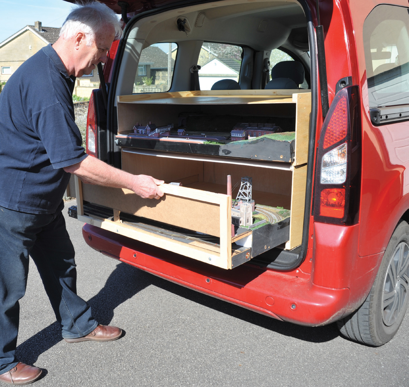
Two boxes (made to fit the width of the car as well as the height width and depth of each baseboard) provide easy storage and good protection when the layout is being transported. They can be carried into a venue to protect the layout from rain, if necessary. The layout with the fitted background is shown being slid into the transport box. The background has been fixed, as the height was needed for the coalmine winding gear, which is just visible.
MULTIPLE BOARD LAYOUTS
If you cannot fit your planned layout on one board, you either have to add additional boards or re-plan your layout. It is simple enough to add additional boards but it brings up a whole host of technical challenges (see Chapter 10).
The greatest problem with having more than one board is ensuring that they join together in exactly the same position time after time. The smaller the gauge of model, the more accurate it needs to be. Fastening two boards together can be achieved in a variety of ways, the most common of which is a couple of bolts with butterfly nuts. Unless the hole is protected, the wood will gradually wear and the joint will become slack, allowing upward and sideways movement. This can be overcome by the use of a suitable diameter hollow steel rod inserted into the appropriate end of both baseboards. Another method is with toggle clips to hold the baseboards together. These have the advantage that you do not have to scrabble under the baseboard to find the locating holes. The third choice is to use hinges where the central pin can be removed to permit separation. All these are adequate methods of joining boards together but to ensure exact registration each time, you need to fit male and female dowels to the joining edges. The cheapest are made of wood, the next best are brass dowels, which require a drilled hole in each baseboard, but by far the best, and unfortunately the most expensive, are brass pattern-makers’ dowels.
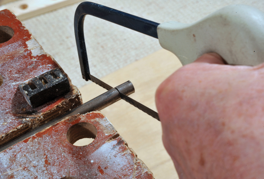
Cutting the steel rod to provide protection from continued wear and to ensure reasonably accurate alignment.
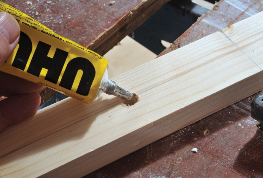
Place glue in the hole that has been drilled to allow the cut rod to be fitted securely.
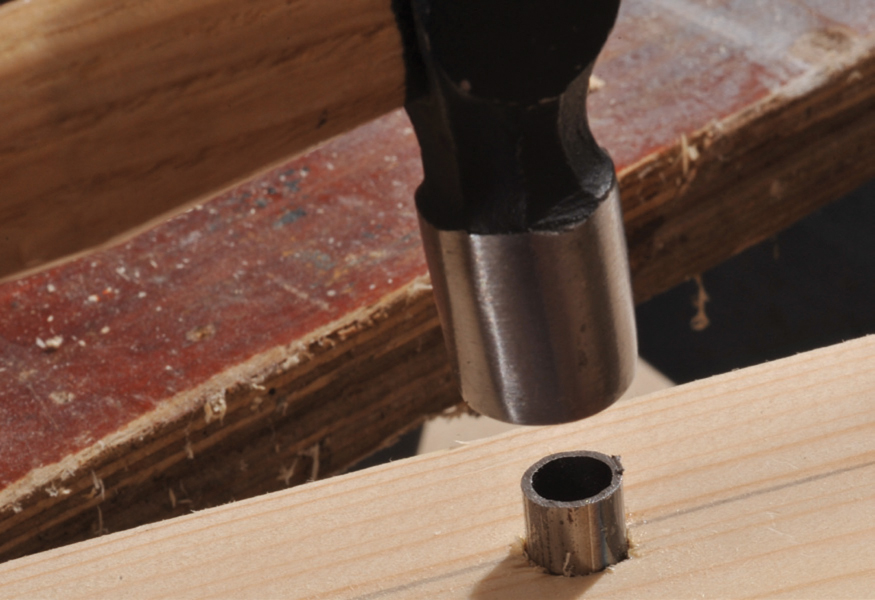
Tapping home the rod into the pre-glued frame.
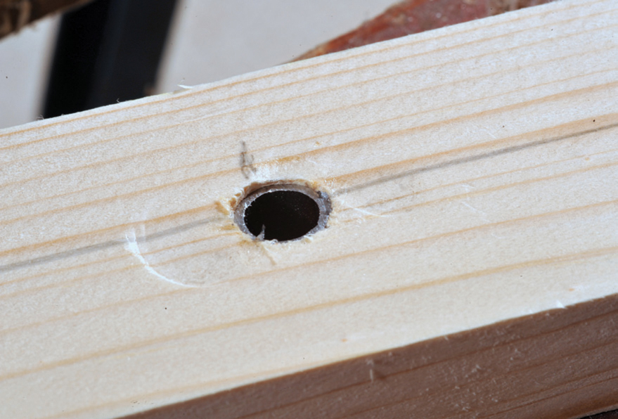
The steel rod in place ready for the bolt.
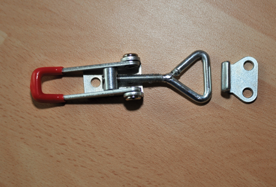
The toggle clamp ready for fitting to the side of the frame to compress the two frames together. Adjustable clamps allow the contact pressure between the boards to be adjusted.
Track wiring will have to be connected between the boards to ensure continuity of supply. Also, power supply to points, lighting and other electrical accessories, e.g. signals, must be linked across the boards in some way.
STORAGE OR DISPLAY SPACE FOR MULTIPLE BOARDS
Brief mention has already been made of the need to plan storage before embarking on construction, but if you are having multiple boards, you need adequate space to either store the boards when not in use, as well as protecting them from damage, or, if they are part of a permanent or semi-permanent display, you need to ensure you have sufficient space both for the boards to be displayed and for access to them both for work and for viewing and keeping them apart during storage.
TRANSPORTABILITY AND SCENERY
Often it is not the problem of transporting in a car or van, but manhandling the baseboards from one site to another and then positioning them to permit accurate joining. Baseboards these days, as will be demonstrated, can be made to be rigid but fairly light. The mistake often comes when scenery is added. Cast models of houses, shops and so on, must be removable, as each unit is quite heavy. Using plaster bandage to make scenery is also much heavier than papier-mâché or polystyrene as the landscape base. The height of the scenery is also a controlling factor. Tall mountains, etc., should be removable and any protruding item should not be too close to either the back or the front or either side of the individual baseboards. I made the mistake of having a station platform near the front with people sitting on benches and I constantly have to stick them back as they become knocked as I stretch across the layout when transporting it.
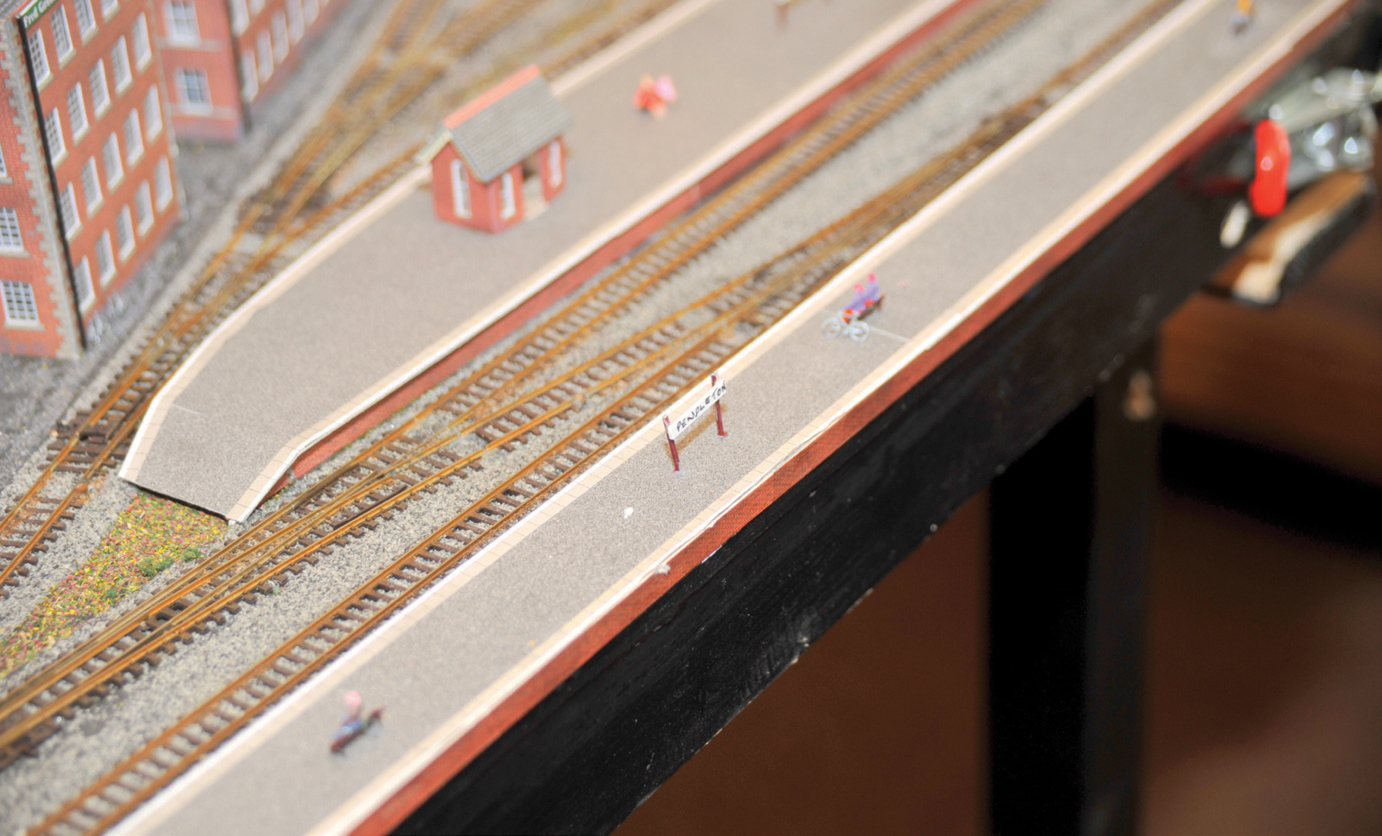
Platform and people. The mistake of putting the platform too close to the front of the board regularly resulted in people or signs being knocked off when the layout was being transported. I now use a bulldog clip to fix a strip of wood to the front when transporting.