
I decided to include this photograph, taken at daybreak along the Blackwater estuary, because for me, it oozes atmosphere, which I would love to try and capture in a model.
BLACKWATER QUAY PROJECT
I have presented here another quayside project based on a small river estuary port, but this time I have scaled it down to 4mm 1:76 scale. The diorama is very loosely based on ‘The Hythe’ at Maldon, Essex. Maldon stands on the Blackwater estuary, therefore I decided to call the model Blackwater Quay. As this model consists of only the quayside area it will be presented as a diorama rather than a model railway, although it could be extended to include more railway operations.

I decided to include this photograph, taken at daybreak along the Blackwater estuary, because for me, it oozes atmosphere, which I would love to try and capture in a model.
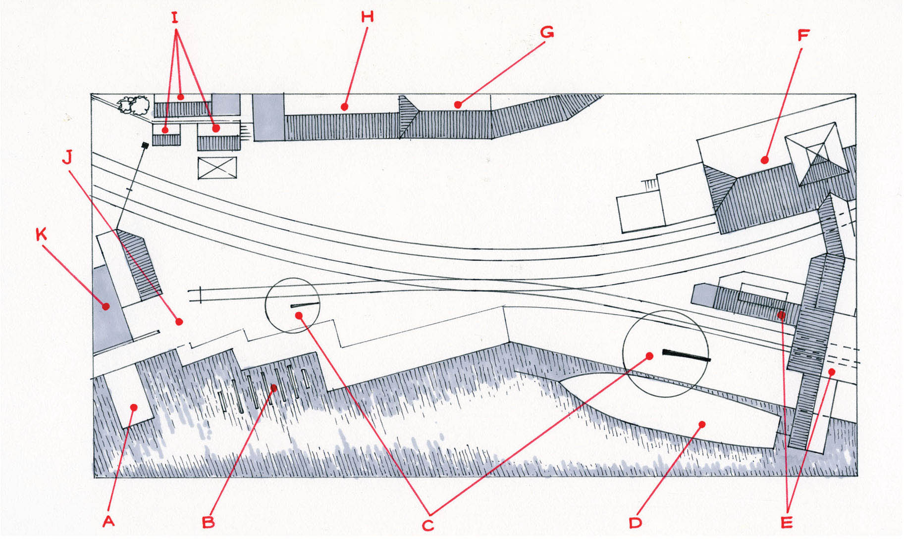
The track plan illustrated is completely freelance, although the buildings are based on ones found in the area. A) slipway B) boat repair cradle C) loading derrick cranes E) grain warehouse F) warehouse G) the Ship Inn H) wharf cottages I) weighbridge and wharf offices J) boatyard K) boathouse.
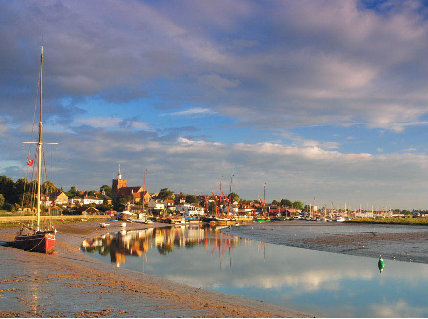
This photograph was taken a little later on the same summer’s morning, looking back towards Maldon and the Hythe Quay. With the low, early morning light picking out the buildings, this would provide the perfect backdrop and setting on which to base my model.

A 3D illustration from my plan of the proposed model of Blackwater Quay, using this as reference, together with all the photographs taken. A reasonable representation of the scene should be possible in miniature. A) slipway B) boat repair cradle C) derrick crane D) Thames sailing barge E) grain warehouse F) warehouse G) the Ship Inn public house H) wharf cottages I) weighbridge and wharf offices J) boatyard K) boathouse.
The first task was to prepare the plan, which was drawn to scale, and in this case a three-dimensional interpretation of the finished model was prepared as well. The next job was to build a baseboard for this diorama. When planning the baseboard I decided to use the sandwich beam method for the construction of the frame sides. This would give the strength and rigidity required, but would keep the board as light as possible. The side frames comprise two strips of 60mm wide plywood fixed together with blocks of pine positioned in between as the middle of the sandwich. The blocks used were 60 × 40mm (2.5 × 1.5in) and 80mm (3in) long. Two beams were constructed, one for each side; these were then glued with PVA and secured using screws to the 4 × 2ft (1 × 0.8m) sheet of plywood to create the baseboard top. Two end stretchers were added, made up from another strip of the 60mm wide plywood; these again were first glued before being secured with screws.
The surface of the plywood top was sanded down, and any defects and any screw heads showing were filled. I used standard woodfiller for this, and then sanded everything down flat. I decided to give the board top a coat of paint as this would be the base for the water; I used a dark camouflage brown spray paint, now available in the Halfords’ range. I did not have to cover the whole of the plywood top however, because the quayside and the land beyond were going to be added next.
To do this, I found a couple of sheets of fibreboard (the sort used for the foundation for laminate flooring). These were ideal, as not only are they light, but the thickness was just right, and they are easy to cut with a Stanley knife or scalpel. The edge of the quay was marked on to the boards, and this was then cut and glued down in position on to the plywood. Extra pieces were cut to shape to form the maintenance and boatyard docks.
LAYING THE TRACK
The fibreboard was also ideal for laying the track directly on to it, without any need for cork underlay. The make of track selected to use for this diorama was from SMP, as this representation of British standard-gauge track has the correct sleeper spacing and good chair detail. The track also comes in metre lengths ready for laying.
The points, however – in this case a single slip – would have to be assembled from a kit, which in this case involved soldering the rail on to copperfaced sleeper strips. The point kits are reasonably simple for anyone who is confident using a soldering iron – though I must confess I am not! The point I used was found already assembled, acquired at a model railway exhibition. Always check over any assembled point work like this before purchasing it, making sure that the point blades fit up to the rail and are level; also check that it is attached properly to the tie-bar. Make sure that any fogs and crossing Vs are also level, and that there are no obvious obstructions. It is not always practical, but if you can, ask if you can run a wagon through the point to make sure everything is good.
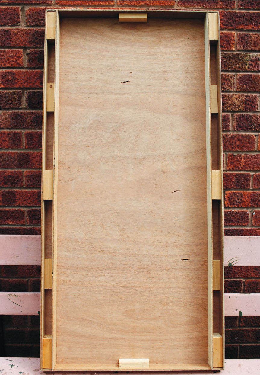
The model’s construction will start, as always, with a baseboard. In this view the construction for the frame is clearly shown. I opted to use the block and beam method for the sides, to give it both strength and stability. I have also used single strips of plywood for the end stretchers, and 3mm ply for the baseboard top.
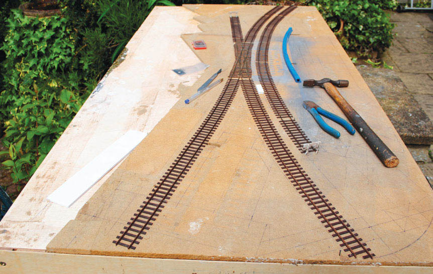
The quayside is first cut to the shape, then glued and secured to the plywood baseboard. I used 9mm fibre insulation board for this, the type used for the foundation under laminate flooring.
The single slip point was going to be fixed down first, before any further fixing, so it was placed in position with the tie-bars marked where they appeared on the baseboard. The point was then taken away so that two slots could be cut through both the fibreboard and the plywood underneath: these slots are to accommodate the operating pin from a point motor fixed underneath the baseboard. The pin will then locate with the tie-bar, providing the mechanism for the point to be switched over to the desired direction. Before fixing it might be worth drilling a few holes for the wiring of the point. Once this has been done and tested, the single slip point can be finally fixed into position. I used a few track pins first, the idea being that these would either be lifted out or cut off later when the glue and ballast had secured the point in position.
Now the rest of the track can be laid to fit up to the point. Most of the track would be on a curve, with just the siding into the boatyard and the wharf remaining straight. To achieve the gentle curves required, I would recommend using one of the track templates supplied by the likes of Peco. Fishplate joiners can be used for any joints, though make sure you use the correct ones required for the electrical circuit to work properly. The lengths of track were first pinned in the same way as the point, before the glue and ballast were added to secure it to the fibreboard. It would be worth looking at the baseboard joins now. This is a tricky job, which must be right in order for the trains to run freely from one board to another. You will also have to make some kind of electrical connecting method to continue the electrical contact over the join.
The best way to join the boards together and make sure that everything is aligned over the joint is by using pattern-maker’s dowels. The sets of dowels come with one male and one female: the males would be fixed to the end stretcher of one board and the females fixed to the end stretcher of the next board.
BALLASTING AND PAINTING THE TRACK
Moving back to the track, all that remained to do was to ballast and paint it. First, I mixed the fine 2mm-scale ballast with some barbeque ash, and sprinkled it over the track. I then carefully brushed it off the tops of the sleepers and the tops of the rails, and anywhere else where it had spilled over. The next stage was to soak the grains of ballast and ash with water, using a garden mister: this will gently soak the ballast without washing everything away.
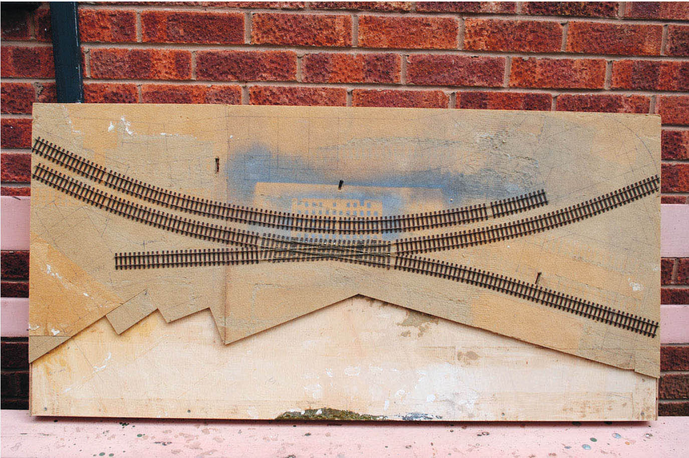
The track layout and the edge of the quayside can be seen clearly in this view. The left-hand side has been cut away to accommodate the boat repair yard, together with its slipway.
The next task was to make up a mix of PVA with water, roughly about 50 per cent of each. It is always worth adding a few drops of washing-up liquid to the mix, as this will help break down any surface tension that might occur. To apply the diluted PVA you will need either an eye dropper or a syringe; load this with the mix and then squeeze it out into the damp grains of ballast and ash. The liquid PVA will spread between the grains, bonding them together and bonding everything to the foundation, before leaving it to dry off completely.
The ballast and the track can now be painted, using oil paint for the ballast and Humbrol matt enamel for the rails and chairs. A mix was made of oil paint using Payne’s grey with small amounts of yellow ochre and mixing white added. A good amount of turpentine was added to this to make a wash, which was then brushed over the ballast. The wash of paint will flow and soak into the grains, giving convincing results. I used a mid-brown Humbrol No. 82 to replicate the rust colour of the rails and the chairs, using a fine No. 1 brush to paint them.
CONSTRUCTING THE QUAYSIDE
Moving away from the track work, a start was made on the quayside. The walls are made of two different materials, the main quay from stone masonry and the walls of the boatyard area from timber. Starting with the boatyard, I looked around for the best material to replicate its construction; I finally decided to use matchsticks, which would be about the right size for the planking at this scale – although the prospect of fixing these together was rather daunting at the start! But once I had laid and secured the first few rows it did not seen too bad, and it wasn’t long before this section of quayside wall was complete.

The quayside walls along the stretch for the boatyard are made using timber planks. I decided that matchsticks would be fine to replicate the material at the scale I was working to.
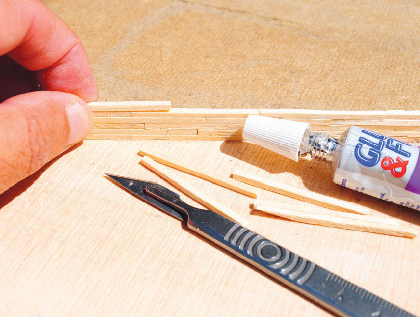
This construction process did take quite a while, but the result was rewarding.
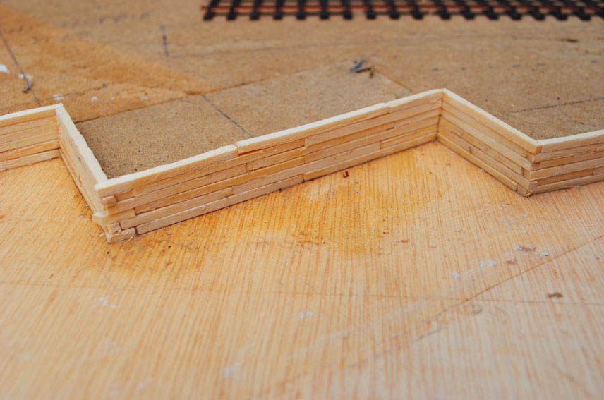
The finished result.
The matchsticks were glued together with an impact adhesive, trying to prevent the glue from wandering on to the face of the sticks. The matchsticks did require cutting from time to time, especially on the construction of the corners to the docks, but overall the finished result looked reasonably convincing. All that remained was to add the wooden pilings at regular intervals across the front. I used balsa-wood strip for most of these, although rocket sticks were also used again for a few.
Now moving on to the main quayside, this was going to slope up to the highest level from the boatyard end; I used a strip of mounting card with the slope cut at the appropriate end. This was then covered with a thin skin of Das modelling clay applied into a coating of PVA. Special care was taken to make sure that the wall stayed flat when it was drying out, as the clay and the PVA glue will both shrink when drying, and will tend to warp a strip of card like this. To prevent this happening I put a couple of heavy books as weights on to the strip while it was drying, leaving it like this for around twenty-four hours. I could then move on to scribing out the stone masonry: I followed photographs of various prototypes, and this resulted in a convincing-looking quayside wall.
The last job was to fix the wooden pilings into position. For all of these along this section of quay I used old spent rocket sticks, which suited the purpose perfectly.
The next task was to create the quayside on top of the facing walls. For this I used various types of card, although foamboard was mostly used in its construction. The boatyard area just needed filling in up to the top level of the planking. The main quay, however, had to be built up, especially at the high point, to make a platform, with the level ground on the railway siding side. This was constructed from strips of 3mm foamboard, creating a framework to support the top of the quay.
The tops could all now be cut to shape and glued to the sub-base, and in the case of the platform, on to the prepared framework. I used the 2mm mounting board for all the tops, which was then coated in PVA, before another thin skin of Das modelling clay was applied. Once this had completely dried off, the cobbles and edging stones were all scribed out – a fairly long laborious job, but well worth it for the results achieved.
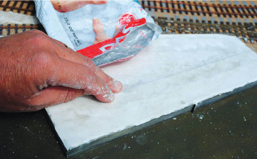
Starting to add the Das modelling clay along the quay’s surface.
PAINTING THE QUAYSIDE
Before moving on to the water again, the quayside together with the facing walls would need to be painted. As for all my painting projects, I used artist’s oil paint. I started with the timber planking, and mixed a colour to represent the ageing timbers, all the time following reference photographs taken of such timbers. The paint from the tube consisted of Payne’s grey, Naples yellow and mixing or titanium white, mixed with plenty of turpentine to create a wash. When applied to the wooden matchsticks, representing the planks, the paint wash soaked straight into the grain. This was also the case with the other wooden parts used on this section. I still intended to follow this up with a drybrushing technique, to give that aged silvering finish to the dry part of the old timbers.
The next painting challenge was to create the stone masonry colour along the main quay walling. This was executed in exactly the same way as the 7mm scale wall on the Porthwenn project covered in Chapter 2, using a wash of paint first before drybrushing to finish.
The next painting stage was to look at creating the tide or high water mark along both walls; this was simply achieved by using a darker colour to anywhere below this line. The process was explained in the previous chapter, though always be aware of the scaling down required. The seaweed and slime would be best replicated by just using paint in the smaller scale perhaps. The clear varnish to create the wet look will still need to be added, but keep this to a minimum of one light coat only.
The tops can now be painted to pick out the cobbles used, and the edging stones to the main quay. The technique and paint used to replicate this has already been explained, but just be aware of the scaling down of colour. You may have to go over the dry brushing a few times to achieve a weathered finish to the cobbles.
While we are looking at the painting techniques used on the model, it will be worth now going over the water with another coat of paint. For this I mixed some burnt umber and yellow ochre, together with a small amount of terra verte. This gave a deep colour, to represent the depth to the water required along the front of the quays. This coat will take a few days to dry before any more work can proceed on the diorama.
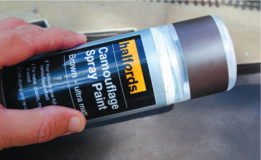
Here, the first coat of paint is applied to the river. I have used ‘Camouflage Brown’ from the Halfords’ range of acrylic sprays. This was sprayed straight on to the face of the plywood, though first, any defects in the ply, or any screw heads showing, were filled with woodfiller and sanded clean.
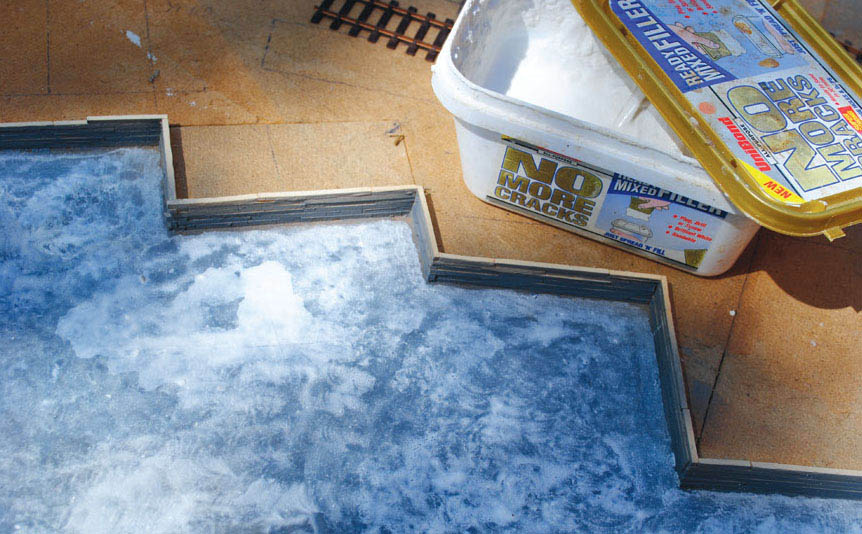
In this photograph the slight ripple has been added to the surface of the water. This was achieved by using ‘No More Cracks’ ready-mixed plaster filler. By using a dapping technique a reasonable effect can be obtained.
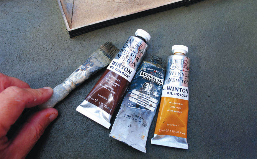
Once the plaster was dry, the whole of the surface area was painted again. By using artist’s oil paints, a mix of raw umber, Payne’s grey and yellow ochre resulted in a colour that resembled the depth of the water.
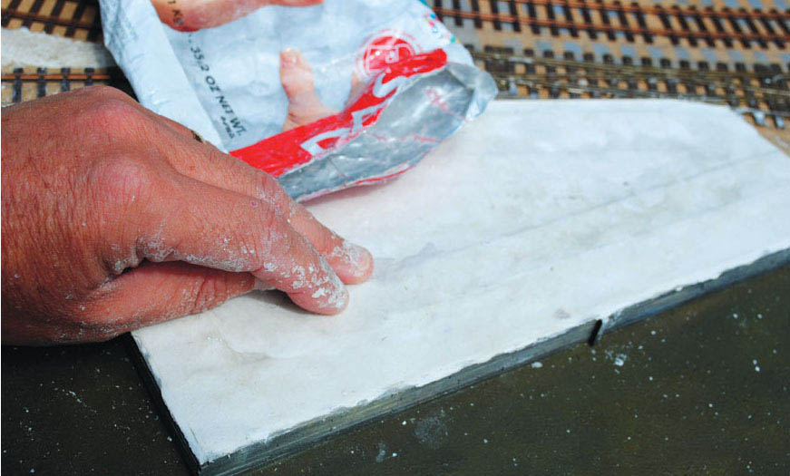
The next stage was to add a skin of Das modelling clay to form the top of the quaysides.
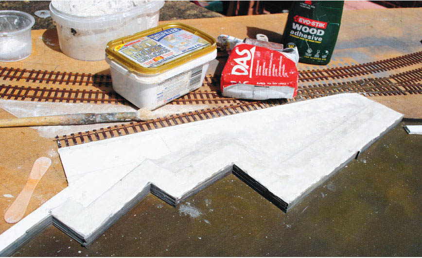
More Das clay was then applied to the area between the quayside walls and the edge of the sidings.
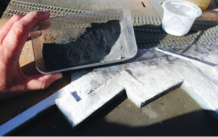
The fine ash ballast is added to the area edging on to the sidings. This was bonded to the surface using diluted PVA.

Once the ballast had dried, it was painted with a wash of oil paint. The rails and the chairs were also picked out using rust brown colour enamel paint. The painting of detail such as this will require careful attention using a fine brush.
EXTRA FEATURES
Once the paint is dry, a few extra features will need to be included in the docks alongside the boatyard: a wooden cradle, a slipway and wooden runner rails.
WOODEN CRADLE
A wooden cradle is provided so that boats can be worked on at low tide. The boat would simply have been positioned and anchored on the high tide over the cradle, and when the water level receded, it would be left sitting high and dry on the cradle allowing the hull to be worked on. However, this type of cradle was designed for flat-bottomed craft, and would be of little use to boats with a keel.
The cradle on the model was constructed by once again using lengths of spent rocket sticks. The first task was to mark out the position of the cradle on the surface, and locating where the upright legs would stand. Holes were then drilled straight through the baseboard top to accommodate them. For this scale, I used a 4mm drill bit to fit 4mm square posts or legs. These had been pre-cut to length and fitted snugly into the holes drilled, before being glued in to secure them. The cross-bar beams were then cut to length and fixed across the upright legs. I used track pins to make the fixing although I did use a little glue as well. The two bars at each end were purposely cut shorter to accommodate the bow and stern ends of the boats.
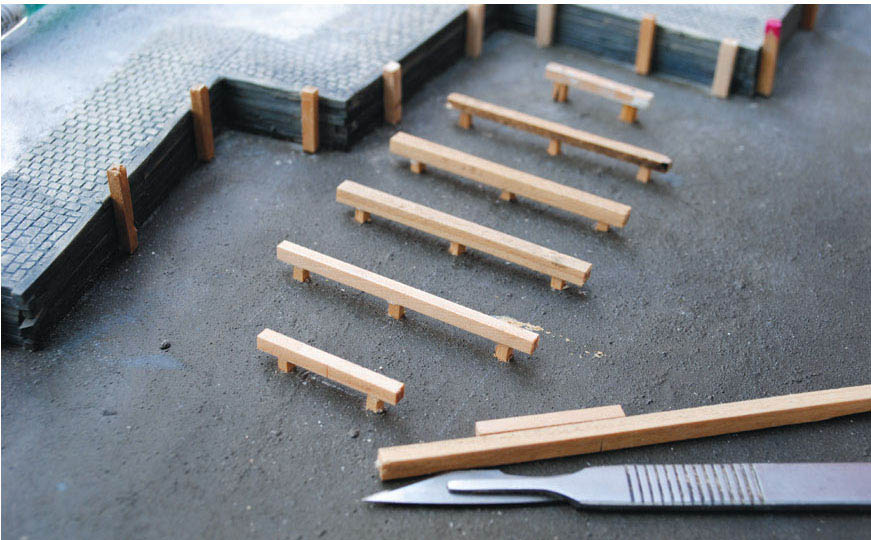
The construction of the boat repair cradle, using 4 × 4mm strips of wood.
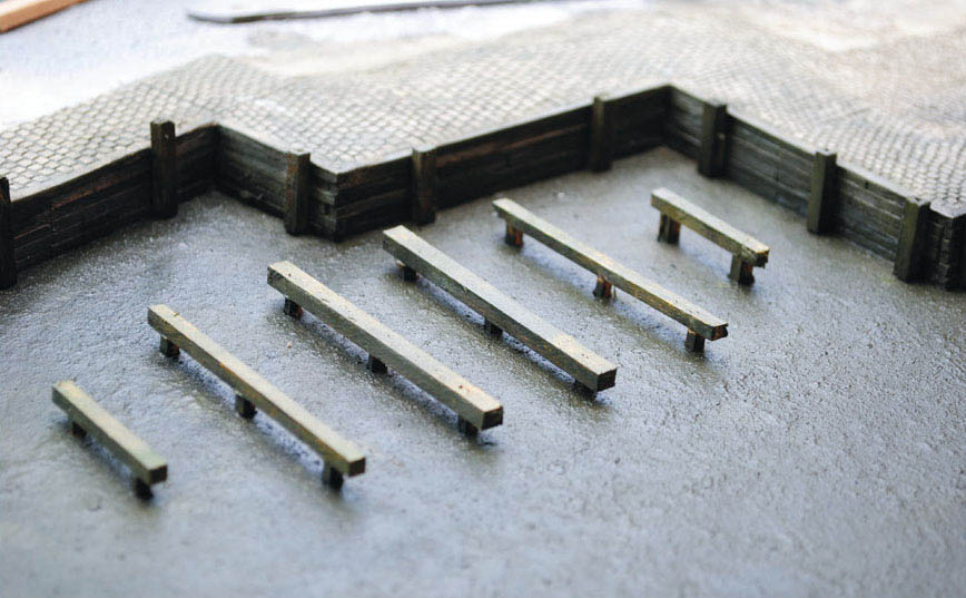
The finished result, painted with oil paints to represent the aged and weathered timbers, with varnish added to the timbers that are submerged under the water when the tide is in.
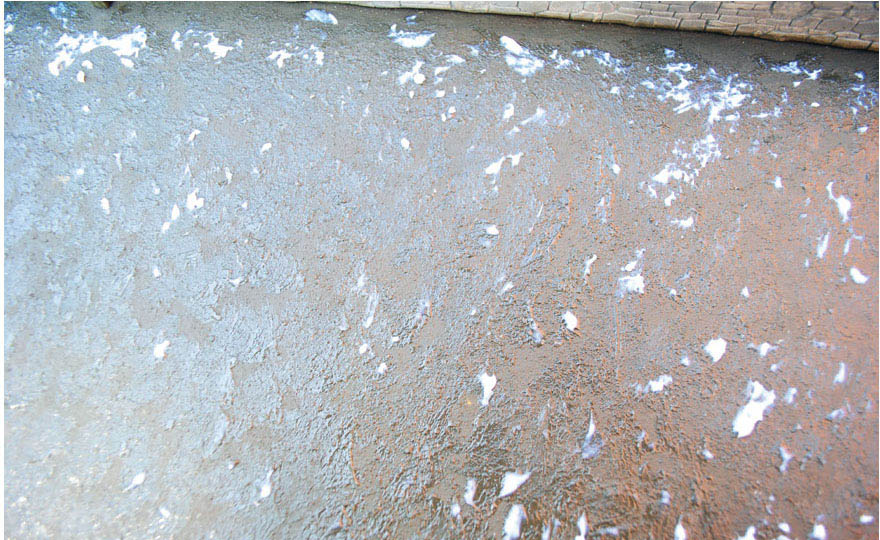
To add to the ripple in the surface of the water, I experimented with the ‘Making Waves’ product from ‘Deluxe Materials’; the white resin was dapped on, trying to keep the direction constant.

The ripples and small waves created can be seen after a top coat of clear varnish has been added. Careful attention was made when applying the varnish around the boat repair cradle.
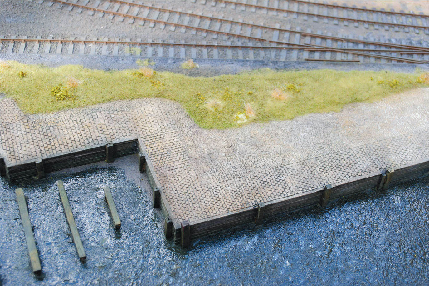
The quayside to the boatyard is now complete. The strip of ground between the quay and the railway sidings has been landscaped to represent the rough grassland and weeds that occupy it.
The cradle was painted in the same way as the timber walling to the quay, although because it would be below the waterline most of the time, it was given that slimy green appearance with paint, and varnish was added to create that damp finish to the timbers.
THE SLIPWAY
The other feature along this quay is the slipway: this was made up from various pieces of card with the front edge cut to a very shallow angle to meet up with the surface of the water. The top of the slipway was coated using a thin coat of ‘No More Cracks’ plaster mix to replicate the concrete textured surface, with the sloping sides coated at the same time.
WOODEN RUNNER RAILS
The last feature to be constructed was the wooden runner rails positioned down the centre. These were provided to haul the boats carrying a shallow keel up and down the slipway. It was constructed from two lengths of 3 × 2mm pine, with spacers made from mounting card fixed and spaced out in between.
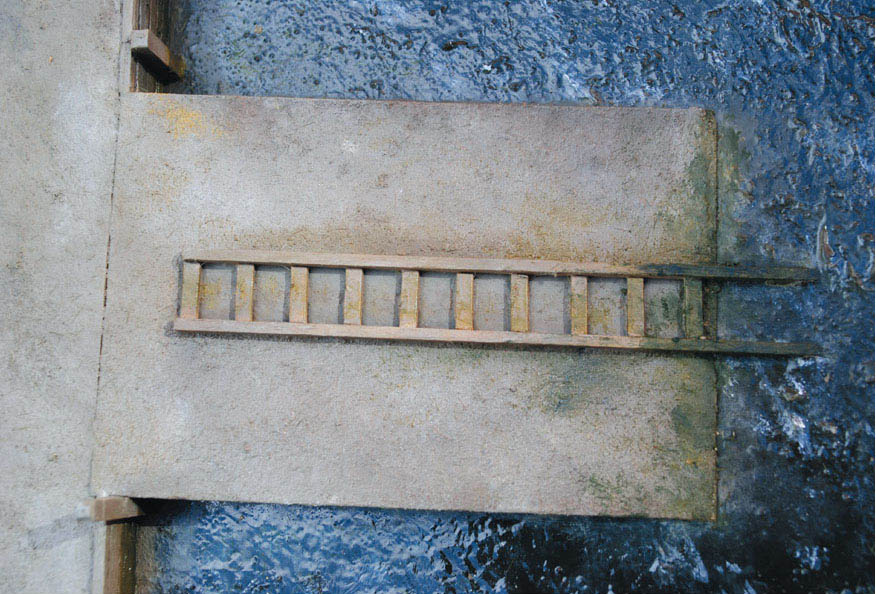
The finished result, with the concrete surface painted using artist’s oil paints. I have also added a little green where the slipway has been under the water, to represent the green seaweed and algae coating the concrete and the timbers.
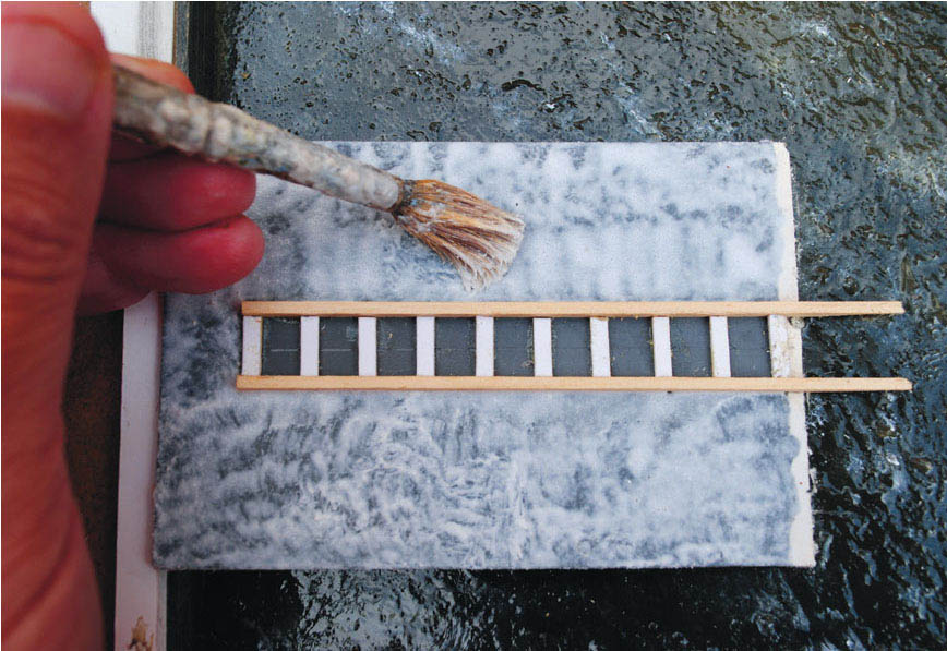
The product ‘No More Cracks’ was used to represent the concrete surface of the boat slipway. Also the rails have been added to accommodate the boat keels.
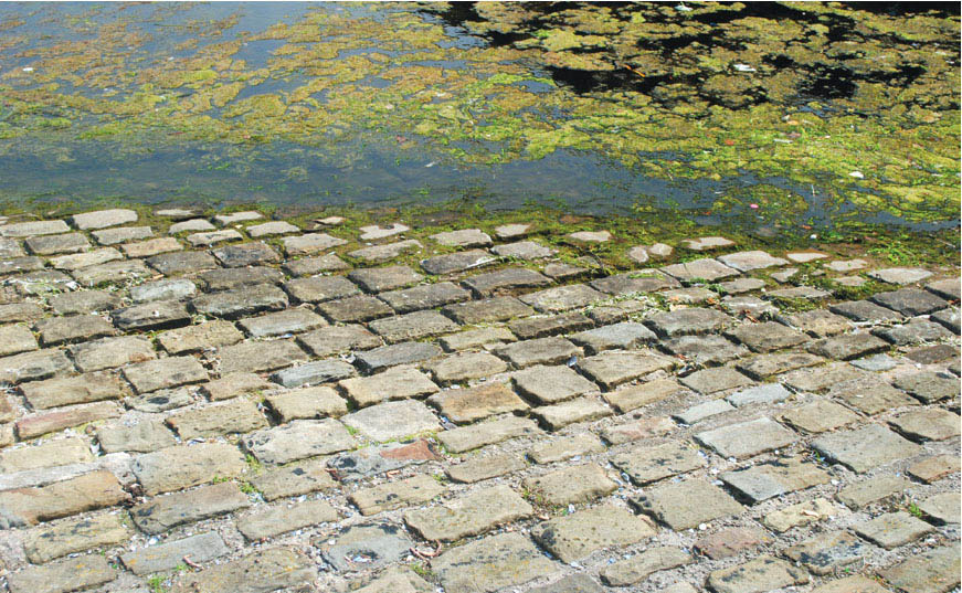
A photograph taken at Liverpool’s Albert Dock basin to illustrate the build-up of green algae and weed found on the waterline of this cobbled slipway.

The wooden quay walls to the boat repair yard on Maldon’s Hythe Quay. These were replicated on the model using matchsticks.

Another view to illustrate the boatyard junk and paraphernalia found at the same yard. This is all worth adding to the model to give authenticity.
With the construction work completed these features now required painting. This was carried out in the usual way using a wash of oil paint first, followed by dry brushing. The colours used from the tube were Payne’s grey, Naples yellow, burnt umber and mixing white. These colours were mixed together to give a replication of the concrete used on the slipway. The wooden rails were painted using light greys, with the lower section receiving shades of green where the rails are under water when the tide is covering them. The green was also spread on to the concrete surface of the slipway to replicate the seaweed, slime and algae building up at the bottom. To finish the slipway a coat of varnish was applied over the green to give the impression of this area being damp.
This completes the quayside project as far as we need go for this book. I have filled in the area between the ballasted track and the cobbles of the boatyard quay: being unkempt, grass and weeds have colonized this strip of land, and I have tried to replicate this on the model by using a mixture of readily available scenic materials. First I used the ‘summer grass’ static grass fibres from Green Scene, and some dry grass from Double O Scenics; both of these were applied using the static grass applicator. Next, a few clumps of teddy-bear fur were added. To complete the scene, Woodland Scenics foam flock was also added to represent the weeds.