Sometimes just a little planning can save a lot of headaches. The design grids discussed in this appendix are intended to save you some of the frustration that comes from not mapping out the direction you want your work to take. The grids are graph paper created with dimensions that match those of LEGO elements. You may find them useful for experimenting with different part combinations before actually getting your bricks out on the table.
You can use the design grids to plan a small part of a large model or the layout of an entire mosaic. Ultimately, their use is up to you, but here are some suggestions for how to use them effectively.
By downloading and printing your own copies of the design grids, you ensure that they’re sized correctly and that you can make as many copies as you need. You can download the design grids (as PDF files) from http://nostarch.com/legobuilder2/.
Each design grid has a different purpose. Design Grids #1 and #2 are most useful when you’re sketching out mosaic images or planning a model that will be viewed from the top looking down. Design Grids #3 and #4 allow you to imagine a LEGO model as seen from the side.
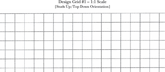
Design Grid #1 allows you to look straight down on the studs of a model. As you can see in Figure B-1, each square is exactly the size of a real 1×1 brick.
Design Grid #2 is unique in that it’s the only one that doesn’t have lines drawn to exactly the size of real LEGO elements. Instead, it’s made up of a 32×32 field of squares sized to fit on a single page. You might use it to plan a mosaic that fits onto LEGO’s common 32×32 waffled baseplate.
As you can see in Figure B-2, this grid also makes it easy for you to pinpoint any location on the baseplate by placing letters and numbers next to the squares of the grid. For example, in Figure B-3, I’ve marked an X in some of the squares on the grid. I can identify these locations by the letter and number combination that meets at that square.
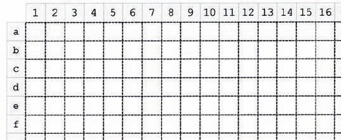
Figure B-2. Like the reference markers on a map, the numbers and letters help you determine where bricks need to go.
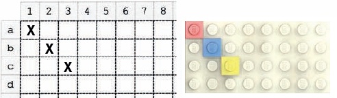
You may find these coordinates useful when transferring your mosaic design from paper to actual elements. For example, in Figure B-3, the Xs on the design grid show where pieces should go. On the right, you see the actual LEGO pieces in the same locations on the baseplate. The red 1×1 plate is at A1, the blue plate is at B2, and the yellow plate is at C3.
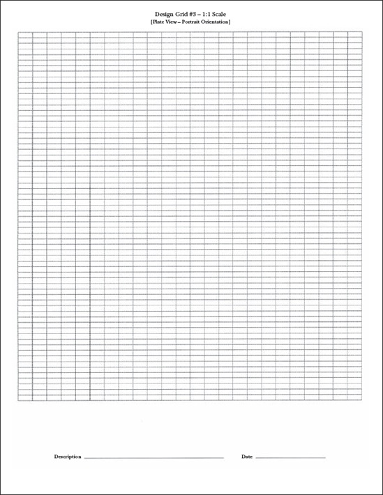
Design Grid #3 allows you to plan a model as though you are looking at it from the side. A portion of the grid is shown in Figure B-4. You can see that the boxes (or cells) on this grid are much shorter than the ones in Design Grid #2. In fact, each box is the height and width of a standard 1×1 plate as seen from the side. This configuration is referred to as plate view.

As with real plates, three of these boxes equal one standard 1×1 brick in height. The page is set up the way a standard book is, with the short sides of the page at the top and bottom. This is known as portrait orientation (see Figure B-5).
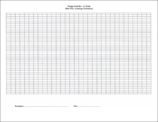
Design Grid #4 has the same size squares as Design Grid #3, but the entire page is oriented with the long sides at the top and bottom. This is known as landscape orientation. The image of the grid shown in Figure B-6 is reduced in size so that you can see the orientation of the squares as they appear on a full page.
As noted earlier, the grids fall into two categories. Design Grid #1 is useful for creating things like the floor plan for an office building, an airplane’s wings, or the layout of walls surrounding a castle. Design Grid #2 is most effective for planning small, studs-out mosaics. Design Grids #3 and #4 allow you to plan the height of a model and include the side view of such things as slopes and plates. You can also use them to plan studs-up mosaics or help you design custom-sized arches made from inverted slopes.
Your choice of grid will depend on which part of the model you are trying to design. If a large model won’t fit on a single grid, use the grid to work out only a portion of the model, or tape several sheets together until you have enough room to complete your design.
You should use two, three, or all four of the grids when designing a model. For example, if you’re sitting down to design your own version of the train station model from Chapter 3, you might use Design Grid #1 to plan the walls, including the ticket counter and the front door; Design Grid #3 to experiment with combinations of parts or ideas for substituting parts; and Design Grid #4 to sketch the front of the train station including the windows and the bench.
Because the grids are sized to the exact dimensions of LEGO elements, you can use them to sketch out your model on the grid, not worrying about which pieces go where, or to draw specific pieces onto the cells to see how they look.
You can also use the grids to test out color combinations. To do this, draw the outlines of the pieces with which you want to experiment, and then color them with colored pencils, crayons, or fine markers. You can even test the look of color combinations for parts you may not own.
Spaces at the bottom of each grid offer a place to fill in the description of the model and the date the design sketch was made. Figure B-7 shows an example.

Figure B-7. Descriptions don’t have to be fancy. Jot down just enough information to remind yourself of the purpose of this particular design.
Keep your designs on file so that as you design new projects, you can look back to see what did and did not work.
Remember, Design Grid #1 presents a view of your model as if you’re floating high above your design. You can see only the tops of any object from this view. For example, if you were to draw the Empire State Building microscale model (from Chapter 6) onto a copy of Design Grid #1, you would end up with something like the drawing shown in Figure B-8.
You can use this grid to determine the various heights of layers within the same model. For example, in Figure B-8, I’ve used shading to represent different levels of the building—light and dark grey, diagonal lines, and blank areas. The shading reminds me to pay attention to the changing geometry as I construct the building and allows me to represent three dimensions on a two-dimensional diagram.
You can also use Design Grid #1 to plan the outline of a model or part of a model (as with the shuttle wings in Chapter 9), or to see the distances between walls within a building (as with the train station example from Chapter 3) or between two small buildings.
If you’re going to use Design Grid #1 for outlining, draw a line around the outside of the shape, and then use the grid to fill in the needed bricks. Figure B-9 shows part of the shuttle wing from Chapter 9.
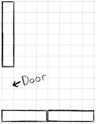
In the case of buildings, you can use the grids to place the walls, doors, and windows. Figure B-10 shows a portion of the train station walls from Chapter 3.
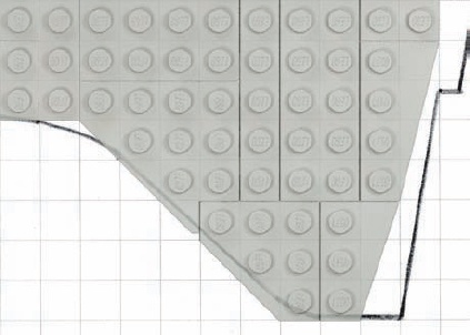
Figure B-9. Using the design grids, you can piece together a model design by placing real elements on your paper sketch.
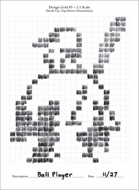
And you can use Design Grid #1 to help plan studs-out mosaics. Studs-out mosaics aren’t as subtle as the studs-up variety, but they can still be fun to plan and build. (See Figure B-11.)
If you’re having trouble seeing your original image through the design grid, try using a light source coming from behind, as I did in Figure B-12. This made it much easier to transfer the figure I wanted to my paper plan.
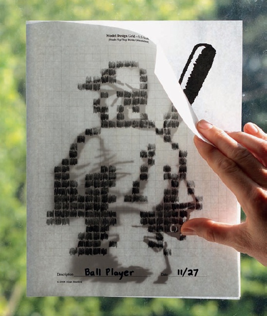
Got an image you want to turn into a 32×32 mosaic without having to use software? Rather than pixelating your image (as I did in Creating Photo Mosaics in Creating Photo Mosaics), you can print and trace an image, just like the method shown in Figure B-12. To plan a mosaic this way, print out a copy of Design Grid #2 and a copy of your image. Make sure to print your image within the length and width of the grid (6.5 inches × 6.5 inches, or 16.5 cm × 16.5 cm). Then place the grid on top of your image and trace the shapes and lines you see coming through.
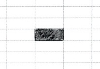
Design Grid #3 has you look at your model from the side. If you were to simply draw a single 1×1 plate, it would look like Figure B-13. A standard 1×1 brick would look like Figure B-14.
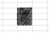
As you can see, each time you want to draw the equivalent of a full-height 1×1 brick, you simply draw a line around three of the cells. You draw longer bricks, such as a 1×N bricks, by extending the top and bottom lines horizontally until you have captured the length you need.
You don’t need to limit yourself to just standard bricks and plates; you can draw other pieces just as easily. Figure B-15 shows what a 1×4 arch brick would look like when drawn on this grid.
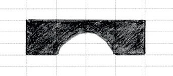
Figure B-15. Parts with complex shapes, such as this arch, can also be easily drawn on the design grids.
You can indicate slopes on this grid by drawing diagonal lines along with lines for the bottom and side of the element (see Figure B-16).
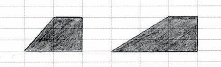
For example, in Figure B-16 you can see a 2×1 45-degree slope and a 3×1 33-degree slope. Notice that the diagonal lines cut across the lines of the grid itself. If you’re ever confused about which lines to connect to make the sloped side of a piece, just grab an actual slope from your collection and study where the slanted edge meets the rest of the brick. (Don’t forget to leave a flat line at the top to represent where the stud is located.)
Once you understand how to use Design Grid #3, you know how to use Design Grid #4. The only real difference between the two is the way they’re oriented: Design Grid #3 is used in portrait orientation, whereas Design Grid #4 is in landscape. You’ll find Design Grid #3 useful when your model is taller than it is wide, and Design Grid #4 works well when the model is wider than it is tall.
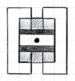
Figure B-17 shows how to test a particular combination of parts to view their final shape without taking any pieces out of storage. As you can see, the drawing isn’t perfect, but it can help you make some key construction decisions.
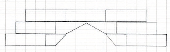
Figure B-17. Inverted slopes are just as easy to draw as their standard counterparts. Here I’ve sketched out a substitute arch, like the example in Chapter 3 (Figure 3-25 in Substitute Windows).
You will always need to tweak your model as you translate it from a sketch into real bricks, but by doing so, you should end up with a stronger design. The drawings you create on the grids provide a guide; you don’t have to follow them brick for brick. The best thing to do is to create your design sketch and then simply start building. As you work, step back and examine the actual assembly to see which bricks or plates you want to change. The result, whether it’s a small group of pieces or a complete mosaic portrait, will be a work of art that you can call your own.