3
Characteristics of a UD Ply in a Given Direction
3.1. Off-axis tensile test
When performing a tensile test of a UD composite off of its orthotropic coordinate system, we observe that this tension along the x-direction creates an elongation along the x-direction, shrinking along the y-direction and also shearing. This is described as tension–shear coupling. In physics terms, this coupling is explained by a lower stiffness in the transverse direction, meaning that the material has a tendency to stretch in that direction rather than in the longitudinal direction.
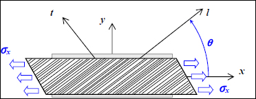
Figure 3.1. Off-axis tensile test of a UD ply. For a color version of this figure, see www.iste.co.uk/bouvet/aeronautical2.zip
This coupling is also visible on the stiffness matrix that presents non-zero components Q16 and Q26 in the frame (x, y). In order to determine the stiffness matrix in this frame, we use the following procedure: we begin by inserting the stress in (x, y). Obviously, we know what they are since they are imposed by the test (even if this is not initially evident, we can demonstrate that the stress shown in the previous figure is in fact a state of pure tension despite the overall deformation in the shape of a parallelogram when dealing with small displacement theory). Next, we determine this stress within (l, t) via a rotation then we determine the strain within (l, t) using the reference stiffness matrix and, finally, we determine the strain within (x, y) via rotation. We then obtain the stiffness matrix in (x, y), i.e. the relation that binds stress and strain in (x, y).

Figure 3.2. Principle for calculating the stiffness matrix in (x, y). For a color version of this figure, see www.iste.co.uk/bouvet/aeronautical2.zip
We therefore begin by determining the stress in (l, t) from that in (x, y).
Where  is the rotation matrix from (x, y) to (l, t):
This can also be written as follows:
An equivalent procedure can be performed with the strain by changing θ to –θ and thus s to –s without modifying c:
Taking care not to forget that in the strain matrix the non-diagonal component is εxy and not γxy, with:
Thus:
When we substitute this:
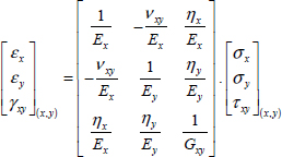
This therefore gives us the compliance matrix:
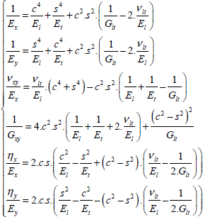
With:
And the two coupling terms ηx/Ex and ηy/Ey, which in general are non-zero save for certain specific values of θ, then cause shear strain for tensile loading and tensile strain for shear loading. If we trace these different coefficients with the values of aforementioned T300/914, we get:
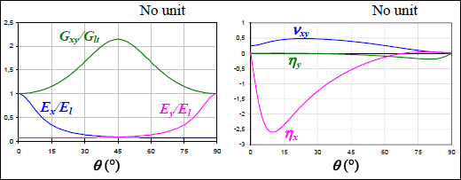
Figure 3.3. Elasticity characteristics depending on the angle of tensile loading. For a color version of this figure, see www.iste.co.uk/bouvet/aeronautical2.zip
We see that Ex is maximum with a value of El for θ = 0°, and is minimum with a value of Et for θ = 90°. The evolution of Ey is obviously opposite to that of Ex. Poisson’s ratio νxy has a value of νlt for θ = 0° and νtl for θ = 90°, and is maximum with a value of 0.48 for θ ≈ 24°. Variations in coupling coefficients are harder to interpret. Coefficient ηx is maximum, in absolute value, when θ = 10° and both coefficients ηx and ηy are evidently null when θ = 0° and θ = 90°. We can nonetheless show that depending on El and Et values, they can present surprising variations. The shear modulus varies relatively less (compared to what it is possible to attain with two plies at ±45°) and is maximum when θ = 45°. This result is significant as it demonstrates that if we wish to obtain an important shear modulus, it isn’t enough to place fibers at θ = 45°, and that there also need to be some at –45°. This result will be demonstrated in the following chapter.
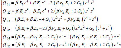
Similarly, we can obtain the stiffness matrix in (x, y):
With:

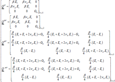
In practice, we mainly use plies at 0°, +45°, –45° and 90° and get:
And:
With:
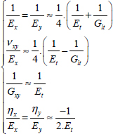
EXAMPLE (Ply at +45°).– For example, in the case of a ply at +45°, supposing that El >> Et and El >> Glt, we get:
We see that the behavior is piloted by the resin, which is logical as no matter what the external stress (σx, σy or τxy) may be, the resin causes an important strain. In particular, if you wish to create a material with a high shear modulus using a UD ply at +45° is insufficient; you will also need a ply at –45° (see Chapter 6).
And for the three basic stress states we obtain:
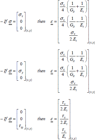
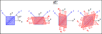
Figure 3.5. The three basic stress states applied to a UD ply at 45°. For a color version of this figure, see www.iste.co.uk/bouvet/aeronautical2.zip
EXAMPLE (Experimental determination of stiffness).– In order to determine the in-plane elastic characteristics of a UD composite, we typically perform three tensile tests (see exercise 1):
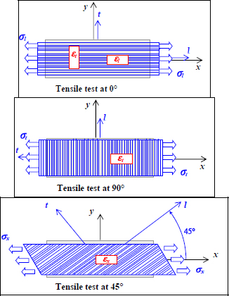
Figure 3.6. The three tensile tests used to characterize a UD ply. For a color version of this figure, see www.iste.co.uk/bouvet/aeronautical2.zip
The first test consists of a tensile test in the direction of the fibers with two strain gauges bonded along the l- and t-directions. We can therefore determine El with the use of the first gauge and νlt using the second gauge:
A second tensile test in the transverse direction with a strain gauge in that direction gives us Et:
Then, the final test at 45° with a gauge bonded along x-direction gives us Glt knowing El, Et and νlt. We can demonstrate that:
Where the only unknown is Glt.


