9
Damage Tolerance
9.1. The principle of damage tolerance
Damage tolerance was defined in the 1970s for civil aircraft structures. These requirements are expressed in the context of European certification JAR 25.571 [JOI 78]: “the damage tolerance evaluation of the structure is intended to ensure that should serious fatigue, corrosion or accidental damage occur within the operational life of the airplane, the remaining structure can withstand reasonable loads without failure or excessive structural deformation until the damage is detected” and by the American certification FAR 25.571 [FED 78]: “an evaluation of the strength, detail design, and fabrication must show that catastrophic failure due to fatigue, corrosion, manufacturing defects, or accidental damage, will be avoided throughout the operational life of the airplane”. As a reminder, the JAR (Joint Aviation Requirement) concerns certification regulations of different classes of aircraft, and the JAR 25 [JOI 78] regulates aircrafts of over 10 passengers or more than 6 tons at take-off. The FAR (Federal Aviation Regulations) 25 [FED 78] is the American equivalent regulation.
The study of damage tolerance can therefore be defined as the behavior of a structure damaged from fatigue loading, corrosion or accidental damage [ROU 95]. The idea is to make sure that the structure is capable of withstanding acceptable loads without fracturing or straining beyond a certain point until damage detection. This concept is the basis for damage tolerance in metallic aircraft structures (Figure 9.1(a)). Indeed, damage propagation throughout metallic structures is relatively slow and generally well controlled. It is then possible to define the intervals between inspections in order to guarantee that the damage will not propagate too much before being detected and will not lead to an interval under UL that is too long. It must also be demonstrated that the structure’s residual strength will always be higher than the LL.
This case is illustrated in the following figure, which offers a diagram presenting the residual strength through time. At first, this residual strength is constant (and higher than the UL) until the appearance of damage (for example, a crack starting at the edge of a hole). This damage will then propagate and the residual strength will then decrease until reaching, if not detected, the LL. We then talk about critical damage. In practice, this damage is detectable starting at a certain length, or rather the airline company must implement the procedure required to detect it before it becomes critical! The minimum interval between the inspections is defined by the amount of time between the moment when the damage is detectable and the moment it becomes critical; the point is to reduce the time spent under the UL. Then, once detected, this damage must be repaired and restored to a residual strength, higher than the UL.
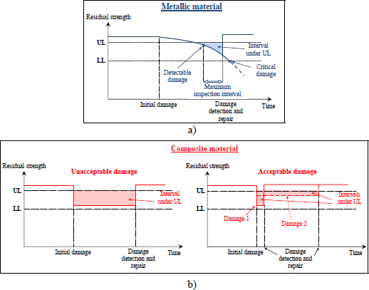
Figure 9.1. General principle of damage detection and repair in metallic a) and composite materials b). For a color version of this figure, see www.iste.co.uk/bouvet/aeronautical2.zip
Nonetheless, it is generally not possible to apply this concept of damage tolerance to composite structures, because composite materials are almost insensitive to fatigue [ROU 95]. This result is (mostly) true for carbon-fiber-based composites, and slightly less for fiber-glass-based composites (Figure 9.2) [ALI 97, BIZ 09]. However, at the same time, the majority of primary aircraft structures (the ones supporting the main loads in the plane) are made from carbon fibers, and we observe that aircraft structures are practically insensitive to fatigue.
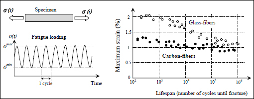
Figure 9.2. Diagram of fatigue curves in a UD laminate composite composed of carbon and glass fibers
This insensitivity to fatigue that is present in composites generally prevents damage from propagating in service. This makes it impossible to define maintenance intervals based on the slow crack growth concept (Figure 9.1), the way we would for a metallic structure. Furthermore, because composites are sensitive to impact, impact damage can rapidly decrease the structure’s residual strength below the UL. Thus, the standard (AC 20-107B [FED 78]) requires the composite be at least as secure as the metallic ones. The objective is therefore to demonstrate that the time spent under UL of a composite structure remains lower than a metallic structure. On top of considering the amount of time spent under UL, another thing to account for is the difference between the residual strength and the UL. In sum, any damage resulting in a residual strength just below the UL (damage 2 Figure 9.1(b)) will take longer to detect resulting in a residual strength that is just higher than the LL (damage 1 Figure 9.1(b)).
Impact damage tolerance in composite structures depends on two main phenomena:
- – The loss of strength caused by the impact; this can reach 50 to 75% of strength without impact [ABR 98, BOU 16]. Obviously, the higher the energy of the impact, the more damage there is and the lower the residual strength (Figure 9.3).
- – The detectability of the impact: the higher the energy of the impact, the more damage there is and the easier it is to detect it. Furthermore, for aircraft laminate composites of standard thickness (a few millimeters), the damage is generally visible from the non-impacted side before it is visible from the impacted side. However, since there is often no way of accessing the non-impacted side (interior fuselage, wings, wing box, etc.), it is only once the impact is visible from the impacted side that it is considered (Figure 9.3).
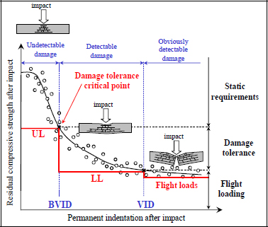
Figure 9.3. Residual strength after impact and detectability of impact. For a color version of this figure, see www.iste.co.uk/bouvet/aeronautical2.zip
This curve (Figure 9.3) of residual compressive strength depending on the permanent indentation after impact (i.e. the dent left by the impact on the composite) is particularly important in the context of impact damage tolerance. First of all, note that the compression is most often taken into account to justify a composite structure to impact damage tolerance, as it is the characteristic that is most affected by the impact damage [ABR 98, BOU 16, AST 05, BER 99]. Indeed, compression fracture is often due to buckling (for standard laminates of a few millimeters in thickness). During impact, numerous delaminations are created throughout the laminate’s thickness that begin to “separate” the laminate into thinner sub-laminates. These sub-laminates obviously present bending stiffnesses that are far lower than the full laminate (the bending stiffness varies depending on the cube of the thickness); this results in local premature buckling under compression, while tension will not be affected by these delaminations.
This curve (Figure 9.3) of residual compressive strength depending on the permanent indentation after impact helps define the load that a structure needs to withstand, and in particular, the three sizing areas of a composite structure to impact damage tolerance:
The undetectable damage area
The structure must then withstand the UL. This area is also defined as the area of static requirements, because the structure’s sizing is governed by static load cases.
The detectable damage area
The structure must then “only” withstand the LL. Obviously, an inspection procedure must detect these damages as quickly as possible. Once they are detected, these damages must be repaired so that the structure can once again withstand the UL.
We also define the BVID (barely visible impact damage) as the smallest detectable damage using a detailed visual inspection. For example, it has been demonstrated that a permanent indentation of 0.5 mm deep was detectable during a detailed visual inspection with a probability of more than 90% [TRO 94] (Figure 9.4); we therefore retain this value 0.5 mm as a BVID.
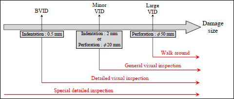
Figure 9.4. Size of detectable damage depending on the type of inspection. For a color version of this figure, see www.iste.co.uk/bouvet/aeronautical2.zip
This area is also defined as the area of damage tolerance, because a structure’s sizing is governed by its damage tolerance. In sum, the damage is there, but we just have to live with it and guarantee that it won’t become more critical before being detected.
Lastly, it is often this area, and in particular the BVID, which is the most critical for sizing a composite aircraft structure to damage tolerances (Figure 9.3), indeed:
A structure presenting impact damage resulting in a permanent indentation equal to the BVID must withstand the UL, and this is throughout the life span of the aircraft.
Imagine, for example, an impact (a tool being dropped) occurring during the manufacturing of the structure causing a permanent indentation just under the BVID. There is no guarantee that this damage will be detected, and it needs to be demonstrated to the authorities that the structure can withstand the UL, and this is for the entire life span of the aircraft. This is, in fact, how a structure is certified for damage tolerance. You start by impacting the structure all over (in particular at critical points!) with impacts that provoke permanent indentations lower than the BVID, then demonstrate that regardless of these damages, the structure withstands the UL.
The obviously detectable damage area
The structure must then withstand the loads required for flight and function as normally as possible (obviously in accordance with the size of the damage!). Once detected, they must be repaired (or the damaged area be changed) in order to withstand the UL once more…
We also define the VID (visible impact damage) as the smallest damage immediately detectable in standard inspection conditions. It has, for example, been demonstrated that a permanent indentation that is 2 mm deep (or a perforation that is 20 mm in diameter) was detectable during a general visual inspection (inspection that is shorter and less in-depth than a detailed visual inspection) with a probability of more than 90% [ROU 95, TRO 94] (Figure 9.4); this value of a 2 mm indentation is therefore generally used to define the VID.
This area is also defined as the flight loads area, as these flight loads govern the sizing of the structure. In sum, the impact was sufficiently high that it was easily detected, and the flight must be completed despite that, in the best possible conditions. In reality, this area is divided into smaller subsections with serious damage, very serious damage and critical damage [TRO 94, BOU 16] (for example, the minor and large VID defined in Figure 9.4).
9.2. Damage during impact and compression after impact
Before focusing on the criteria used to size a composite in the context of impact damage tolerance, we should start by discussing what impact damage looks like and how this damage develops to lead to the final fracture during compression after impact (CAI). Take the simple case of a laminate [0,90]S. During impact, we observe the appearance of two types of matrix cracking (Figures 9.5 and 9.6):
- – Vertical matrix cracks in the lower part of the laminate due to high transverse stress σt.
- – Matrix cracks at 45° at the center of the laminate under the impactor due to high out-of-plane shear stress τtz. We restate that when there is a bending applied to a plate, the out-of-plane shear stresses τxz and τyz are null on and under the plate, and reach their maximum at the center.
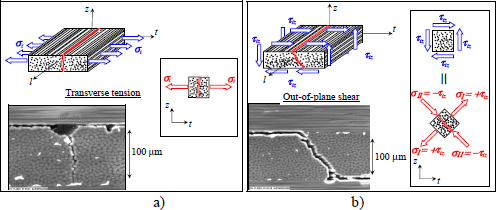
Figure 9.5. The two types of matrix cracks: transverse cracks due to transverse tension σt a) and at 45° due to out-of-plane shear stress τtz b). For a color version of this figure, see www.iste.co.uk/bouvet/aeronautical2.zip
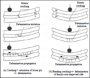
Figure 9.6. Damage scenario during impact of a UD laminate [0,90]S [CHA 87]
As the density of these matrix cracks increases, they create delaminations between the plies, delaminations that will then propagate more or less through the impact area (Figure 9.6). We then see the plies fracturing, beginning with the lower plies (and upper plies) due to longitudinal tension (and compression) σl, then the plies located at mid-thickness due to longitudinal tensile stress σl and out-of-plane shear stress τlz.
Now take the realistic example of a laminate [02,452,902,–452]S (Figure 9.7). In this micrographic cut, we observe the different damages we discussed in the case of laminate [0,90]S: matrix cracks, delaminations and fiber fractures. We note in this figure that the delaminations are present until the junction between two groups of plies in different orientations (and not between two plies directly in the same direction). This is due to the high interlaminar shear stresses τxz and τyz in these areas. Matrix cracks are very pronounced in the area just below the impactor, mainly at 45° (Figure 9.7), due to high out-of-plane shear stresses τtz in this area. In the ply located on the non-impacted face at the impactor location, a wide open vertical matrix crack is present, resulting from high transverse tensile stress σt in this area.
The micrographic cut shows a high delamination of the first interface (noted 1 in Figure 9.7) on the non-impacted face between the two plies at 0° and the two plies at 45°. This delamination is still wide open, and this is despite a null impact force (the cut is obviously taken after impact). We also observe a number of junctions between matrix cracks and delaminations showing the high interaction between these two types of damage. We also note from this figure the permanent indentation under the impactor (which here was approximately 0.5 mm) due to various damages in the impacted area.

Figure 9.7. Damages in a carbon / epoxy UD laminate [02,452,902,–452]S after a 25 J impact. For a color version of this figure, see www.iste.co.uk/bouvet/aeronautical2.zip
The delaminations propagate during the impact in the direction of the lower ply (for example, along 0°-direction for the delamination of interface 1 in the previous figure) because of the high interlaminar stress in this direction. We also observe that the delaminated areas are larger when we go from the impacted face to the non-impacted face (Figures 9.7 and 9.8).
These different impact damages are likely to propagate during the CAI if the compressive stress is too high. During a CAI test, we mainly observe two damage phenomena leading to the fracture:
- – The first damage phenomenon is the buckling of the sub-laminates delaminated during impact (Figure 9.8). These sub-laminates are likely to buckle under compression and then cause the delaminations to propagate, which can amplify the effects of the buckling. This propagation of impact delaminations often takes place in the perpendicular direction to the load. This phenomenon is often catastrophic and quickly leads to the final fracture of the structure. This buckling will be all the more premature during CAI if the plate is deformed, meaning the permanent indentation will be deeper.
- – The second phenomenon is the propagation of compressive fiber fractures of plies oriented along the loading direction. The laminates loaded by compression were designed for this, and obviously presented more plies at 0° than in other directions. A compression crack is likely to appear at the edge of the area damaged by the impactor and propagates during the CAI. This compression crack is due to the local buckling in the fibers; this is the kinking band phenomenon raised at §4.1.2 (Figure 9.8). Furthermore, this crack is generally initiated during impact (because of the high compressive and shear stresses just below the impactor). This phenomenon is generally invisible from the outside, because the surface plies are generally at ±45° (to increase the buckling resistance).
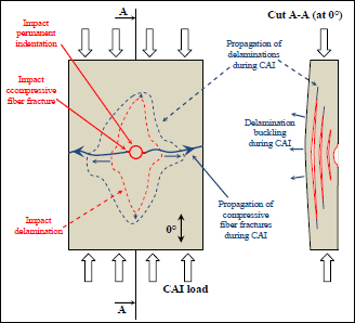
Figure 9.8. Typical scenario of damage and fracture during CAI. For a color version of this figure, see www.iste.co.uk/bouvet/aeronautical2.zip
9.3. Sizing for impact damage tolerance
The composites are sensitive to impact, which means the impact damage tolerance is a case of critical (and complex) sizing for composite aircraft structures. The complexity of these sizing cases arises from the fact that both the impact damage, or more specifically the structure’s loss of residual strength due to the impact and its detectability, or more exactly the permanent indentation left by the impact, must be considered simultaneously.
Thus, in order to justify a composite aircraft structure to impact damage tolerance, we begin by determining its residual strength curve depending on the permanent indentation, and we then show that the conditions of impact damage tolerance are met. It is then a matter of showing that for undetectable damage, the structure is able to withstand the UL, and that for detectable damage, the structure can withstand the LL (Figure 9.3).
Obviously, in reality, the problem is not 1D, and there can be additional stresses on top of the primary compressive loading, in particular shearing. The shear stresses can also have an impact on the post-impact residual strength of a structure. Impact damage (delaminations in particular) is very sensitive to buckling, and since a shear stress is composed of tension at +45° and compression at –45°, this shear stress can induce buckling and therefore cause a significant loss of characteristics after impact. Ironically, there are very little data on the shear strength of a plate after impact; this arises from the fact that shear tests are difficult to implement and utilize.
To characterize the residual strength of a composite structure after impact, we often use the following compression/shear strain fracture criterion:
Where εlcomp is the compressive strain (the tensile strength is not much affected by impact) and εlres and γltres are the longitudinal and shear residual strains respectively. The most complicated thing is obviously defining the residual strains after impact, which depend on the energy of said impact (and therefore the permanent indentation), the stacking sequence, the material, etc. because that requires a large number of experimental tests, which can be long and costly.
One solution consists of determining the data using a numerical model. Let us imagine, for instance, a model that would allow us to determine numerically the residual strength and permanent indentation for all types of structures (built, for example, from a chart depending on the thickness, stacking sequence, material, etc.). Then it can be used directly to justify or design a composite structure with the desired impact damage tolerance. The drawback with this type of approach lies with the reliability of the charts, which are only valid for certain types of impacts and structures (i.e. the ones that were used to create the charts in question). This type of approach is generally used in the aviation industry.
We can also imagine a numerical model that could simulate the impact damage completely, including the permanent indentation and residual strength after the impact. The drawback this time lies with the reliability and complexity of the model. The complete numerical simulation of the impact damage and the CAI of a composite structure is currently a real challenge and is the object of various studies [WIS 12, GON 12, TAN 15, BOU 09].
The problem is all the more complex if we wish to optimize a composite structure to damage tolerance. In this case, only the load is known and the objective is to determine the lightest and/or the cheapest structure possible, satisfying the conditions of impact damage tolerance (as well as static requirements). The problem is complicated by the contradictory nature of both the impact damage tolerance criteria, which are the residual strength and permanent indentation. It is generally required to increase the thickness of a composite laminate in order to increase its residual strength, but its thickness also needs to be decreased in order to improve the detectability of the impact. We can therefore encounter cases where increasing the thickness of a structure will paradoxically reduce its strength to impact damage tolerance by, for example, making the impact undetectable.
