12
Buckling
12.1. Reminder surrounding beam buckling
When performing compression on a beam, we observe a compressive loading at the beginning of the test! By increasing compressive force F, we can achieve buckling, depending on the slenderness of the beam. Buckling is an elastic instability, and we can demonstrate that the problem presents an eigenmode when the compressive load is equal to the critical buckling load:
In this case, the solution to the problem is then undetermined (the solution displacement field depends on an undetermined multiplicative coefficient), and in particular any value of deflection δ is a solution to the problem.
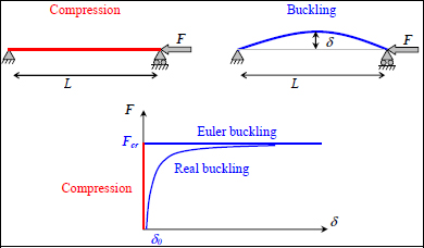
Figure 12.1. Beam buckling. For a color version of this figure, see www.iste.co.uk/bouvet/aeronautical2.zip
Fcr is called Euler’s critical load and has the following value:
where E is the Young’s modulus of the beam, I is its minimum bending inertia, L its length and α is a ratio that depends on the boundary conditions, and is equal to 1 in the example of the beam simply supported at both the ends presented here.
The solution (δ, F) to the problem therefore lies in the horizontal blue line of the previous figure. In reality, the problem is more complicated, as the initial beam is never perfectly linear and will always present a slight initial deflection δ0 and the real curve tends towards Euler’s critical load without ever actually reaching it, because the structure breaks under bending first (Figure 12.1).
12.2. Buckling of plates under compression
Just as with the beams, a compression stress can cause buckling in a plate.

Figure 12.2. Plate under compression simply supported at two ends. For a color version of this figure, see www.iste.co.uk/bouvet/aeronautical2.zip
We can demonstrate that the critical buckling load can be presented as follows:
where C and K are the ratios that depend on boundary conditions and can be determined using a chart according to the characteristics of the plate.
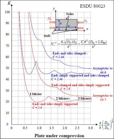
Figure 12.3. Calculation of a plate under compression [ESD 95]. For a color version of this figure, see www.iste.co.uk/bouvet/aeronautical2.zip
In aviation, the case of both ends simply supported is often used (this corresponds to ends and sides simply supported in the chart above). This comes from the fact that the studied plate often corresponds to a panel skin, i.e. a plate limited by four stiffeners. Yet, the torsional stiffness of stiffeners being relatively low, the rotation of the sides of the plate is not impeded, and the boundary conditions cannot be considered clamped. We can nonetheless show that reality is often somewhere between simply supported and clamped, but at the same time the resistance to buckling is dependent on boundary conditions (which are often not well known), and so we prefer to remain conservative and consider the case of simply supported ends.
Note that the previous formula (equation [12.3]) is only valid for a plate with an orthotropic behavior in (x, y), so if the mirror symmetry is respected ( = 0) and if:
We also note that in this formula the critical load is dependent on the characteristics along the y-direction, D22 and b, and on the coupling characteristics D12 and D66. It also obviously depends on the characteristics along the x-direction, D11 and a (via coefficient K). This dependence on direction y can be explained by the deformation which will cause bending around both x and y. As for the dependence on the coupling characteristics, this can be explained by the shape of the blisters. We can demonstrate that the coupling coefficients will upset the blisters and thus delay buckling.
We also note that, depending on the size and bending stiffness of the plate, buckling can occur with different numbers of blisters. For example, for low values of λ:
The minimum value of K is obtained for a single blister, while for higher values of λ, it is obtained with more than one blister. However, the amount of blisters is influenced by the boundary conditions, and we often use the asymptotic value of the simply supported case, i.e. K = 19.7 to obtain a conservative result. Indeed, buckling is very sensitive to boundary conditions, while the boundary conditions are often not well known.
EXAMPLE (Laminate [0n,90n]S).– Consider a laminate with a stacking sequence [0n,90n]S composed of UD 0.25 mm thick plies of T300/914 subject to a compressive resultant force Nx = –1,000 N/mm, with its side a = 300 mm and b = 200 mm simply supported on all four sides (essentially, a sheet of A4 subject to 20 tons of compression).
Determine n, so that it will support the load.
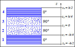
Figure 12.4. Laminate [0n,90 n]S. For a color version of this figure, see www.iste.co.uk/bouvet/aeronautical2.zip
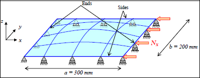
Figure 12.5. Laminate plate [0n,90n]S under compression. For a color version of this figure, see www.iste.co.uk/bouvet/aeronautical2.zip
We begin, for example, by taking n = 2 or a plate with a thickness of h = 2 mm. We then calculate the bending stiffness of the laminate:
We then obtain:
Thus:
And:
This is evidently insufficient to support the presented load. And you will note that the negative sign for the compression is generally not used in buckling tests, but it should be remembered that it is indeed a compression.
By gradually increasing n, we obtain the lowest value of n that will support the load:
which gives us:
We note that to determine n, we can use the fact that the buckling resistance evolves with the cube of the thickness, the same way the bending stiffness does. In sum, if we multiply by 2 the thickness of a plate (with the same stacking sequence but plies that are twice as thick), then we are multiplying by 23 = 8 the bending stiffness and buckling.
We can then verify that under Nx = −1,000 N/mm, the RF (with a Yamada–Sun criterion, for instance) remain over 1:
- – For plies at 0°: RF = 5.89
- – For plies at 90°: RF = 563
This is widely verified here.
We can, nonetheless, easily improve this stacking sequence by adding a ply at 45° and one at −45° at the surface:

We then obtain for:
a buckling resistance of:
And the RF are still well over 1:
- – For plies at 0°: RF = 4.81
- – For plies at 90°: RF = 65.5
- – For plies at 45°: RF = 6.11
- – For plies at −45°: RF = 6.11
This increase remains small but non-negligible. We can therefore demonstrate that to increase the resistance to buckling of a plate, it would be best to place the plies at ±45° outside it. In aviation, it is in fact common to place two plies at ±45° at the surface. This then presents the dual advantage of increasing the buckling resistance and protecting the plies at 0° (which are often the most loaded).
We can then further improve the buckling resistance of this stacking sequence by using only plies at ±45° (even though this type of stacking may result in issues due to matrix cracking):

We then obtain for:
a buckling resistance of:
But this time the RF are lower than 1, since there are no plies at 0° to support the load:
- – For plies at 45°: RF = 0.89
- – For plies at −45°: RF = 0.89
Furthermore, in practice, there is always a minimum of 10% of fibers in every direction! We can therefore correct these RF by adding plies at 0° and 90°:

or:
A buckling resistance of:
And RF above 1:
- – For plies at 0°: RF = 1.85
- – For plies at 90°: RF = 3.40
- – For plies at 45°: RF = 1.93
- – For plies at −45°: RF = 1.93
Keep in mind that, compared with a metallic structure, determining an optimal stacking sequence for a composite structure remains a complicated process even when using only two criteria, here the fracture of the first ply and the resistance to buckling.
12.3. Plate buckling under shear loading
As for a plate under compressive loading, the shear loading can induce buckling. Indeed, the shear stress being tension at 45° and compression at −45°, the compressive component can induce buckling.

Figure 12.6. Buckling of a simply supported plate under shear loading. For a color version of this figure, see www.iste.co.uk/bouvet/aeronautical2.zip
The critical buckling load under shear loading Txycr is obtained using a chart that gives us the evolution of:
According to λ:
Note that this chart is only valid for a simply supported plate on all four sides, but since, at the same time, it is the most commonly used boundary condition in aviation, this chart covers a wide number of cases.
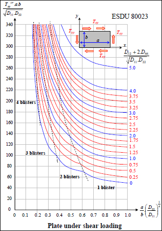
Figure 12.7. Calculation of a plate under shear loading [ESD 95]. For a color version of this figure, see www.iste.co.uk/bouvet/aeronautical2.zip
Once again, this formula is only valid for an orthotropic plate in (x, y), therefore if the mirror symmetry is respected ( = 0) and if:
In the case of a multiaxial load, with Nx, Ny and Txy, the calculation of buckling is more complicated, and even if there exist other charts [ESD 95, MIL 97], we soon find ourselves using finite element solutions. For more details surrounding buckling calculations, interested readers can consult [ESD 95, MIL 97, BER 99, GAY 97], and refer in particular to exercise 8 for the calculation of a stiffened panel.


