4
Analysis of Trusses
The teaching objectives for this chapter are as follows:
- – mastery and implementation of truss analysis methods;
- – distinction between truss analysis methods and their limitations;
- – analysis of the static indeterminacy of trusses;
- – analysis of composite and space trusses;
- – implementation of the matrix method.
In the first part of this chapter, we present the static indeterminacy of trusses. In these structures, we distinguish between external and internal static indeterminacy. The second part describes truss analysis methods. In this part, the joint equilibrium method, the method of sections, the graphical method and the matrix method are described. Lastly, the third part presents the analysis of composite and space trusses.
4.1. Definition of a truss
A truss is an assembly of straight or curved bars biarticulated at their ends, which forms a stable structure. For their lightness and strength, trusses are widely used to solve the problems of range, resistance and aesthetics. Trusses are used in bridges, floors, factories, large sports and conference halls, and domes, etc. The bars of a truss are joined by bolts or rivets through a plate called a “gusset” (Figure 4.1).

Figure 4.1. Connecting gusset1
When the bars of a structure are on a single plane, the truss is said to be plane (Figure 4.2). In general, trusses are spatial and have a perfect (rigid) connection between their bars (Figure 4.3). In many cases, bridge or firm structures are considered to be plane structures, meaning they can be analyzed without influencing the accuracy of the results obtained.

Figure 4.2. Plane truss
Trusses may be statically indeterminate internally or externally. If the number of support reactions is greater than the number of static equations, the truss is said to be statically indeterminate externally. Similarly, the truss is statically indeterminate internally if the static equations are insufficient to calculate the internal forces on the bars.
4.2. Hypothesis of analysis
The analysis of trusses is based on the following simplifying assumptions:
- 1) all the bars of the plane or space structures are biarticulated at their ends;
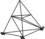
Figure 4.3. Space truss
- 2) the external forces are exclusively applied to the joints of the truss;
- 3) the axis of each bar coincides with the line between the centers of two adjacent joints (Figure 4.4).

Figure 4.4. Model of a truss
In trusses, the loading system only generates forces on the structure’s bars. Each internal force can be a traction, a compression or a zero force (neutral).
4.3. Sign convention and representation of internal forces
For consistent notation, a sign convention is necessary for truss analysis. In reality, there is no universal sign convention. In truss analysis, we will use the positive sign for traction force and the negative sign for compression force. This convention even conveys the physical direction of each force. In addition, the internal traction force lengthens the bar as the compressive force compresses it (Figure 4.5).

Figure 4.5. Sign convention
4.4. Degree of static indeterminacy and stability of trusses
We have already covered the static indeterminacy of trusses in section 1.8. The static indeterminacy of trusses is distinguished on two different levels; it is an internal analysis and an external analysis.
For a truss with b bars, n joints and r support reactions, the degrees of external and internal static indeterminacy can be determined by the formulas discussed in the following sections.
4.4.1. External analysis
The static indeterminacy of a truss is determined by comparing both the number of unknowns of the problem and the number of static equations. Figure 4.6 shows some cases of static indeterminacy of a truss.
r = ne: the structure is statically determinate externally.
r > ne: the structure is statically indeterminate externally and the degree of static indeterminacy is f = r – 3.
r < ne: the structure is unstable externally.
ne is the number of static equations, ne = 3.

Figure 4.6. External analysis of trusses
4.4.2. Internal analysis
Using the same concept as in section 4.4.1, we define the internal static indeterminacy of a truss by the difference between the number of unknowns of the problem and the number of independent equations.
- – The truss is statically determinate internally if:

- – The truss is statically indeterminate internally if:

- – The truss is unstable if:

Therefore, the degree of internal static indeterminacy can be deduced by:
Figure 4.7 shows the internal static indeterminacy of some trusses.
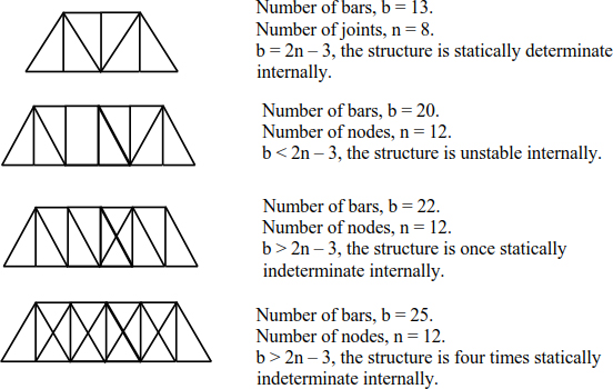
Figure 4.7. Internal analysis of trusses
4.5. Analysis methods of trusses
The primary purpose of truss analysis is to determine the internal forces on the bars. As seen in [4.4], the number of unknowns in a truss is the number of bars in the free-body diagram. So, to analyze it, it is necessary to provide at least b independent equations. In the literature, there are several analysis methods. In this subject, we can identify the following.
4.5.1. Method of joint equilibrium
In the method of joint equilibrium, the internal forces on the bars of a truss can be determined by considering the equilibrium of each joint. The equilibrium of the whole structure makes it possible to check the overall equilibrium. At each joint, the forces on the bars and the nodal forces and/or the support reactions must satisfy the equilibrium equations.
Equations [4.5] and [4.6] are checked at each joint. For this reason, it is recommended to start the analysis with the joint having a maximum of two bars. By successively applying the equilibrium equations at each joint, we can then determine the forces on the bars.
To enrich the analysis using this method, consider the truss (Figure 4.8).
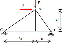
Figure 4.8. Truss
External analysis
The structure is linked to the external environment by two supports; a roller support in B (VB) and a hinged support in C (VC and Hc). If the number of support reactions is greater than the number of the static equations, the structure is said to be statically indeterminate externally.
Internal analysis
Number of bars, b = 5.
The number of independent equations is equal to 2 × n – 3 = 5.
b = 2 × n – 3, the structure is statically determinate internally and externally, the method of joint equilibrium can be applied to calculate internal forces on the bars.
The procedure for analyzing trusses using the method of joint equilibrium is as follows.
Calculation of support reactions
We construct the free-body diagram (Figure 4.9).

Figure 4.9. Free-body diagram

The equilibrium of joint C makes it possible to calculate the forces on bars NCD and NCA.

Joint D:

Finally, the equilibrium of joint B makes it possible to determine the force in the bar (BA).
The vertical equilibrium is sufficient to determine the force in the bar (BA):
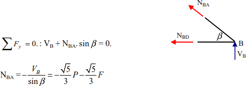
At this stage, all forces on the bars are determined and the equilibrium of joint A can be used to verify the calculation.
The horizontal and vertical equilibrium of joint A is:


The above equalities are verified by substituting the expressions of the normal forces NAC, NAD and NAB.
The forces on the bars are calculated using the equilibrium equations. To distinguish the nature of the internal force and to draw the diagram of normal forces (Figure 4.10), we can look at case P = F. The forces on the bars and their natures are grouped in Table 4.1.
Table 4.1. Internal forces on the bars
| Bar | CD | CA | DA | DB | BA |
| Normal force |  |
 |
0 |  |
 |
| Nature of force | Traction | Traction | Neutral | Traction | Compression |
4.5.2. Method of sections
The method of joint equilibrium presented in section 4.5.1 is effective for calculating the forces for all the bars. However, when we limit which forces to calculate, the method of sections is the preferred option.

Figure 4.10. Normal force*
The method of sections consists of cutting the bars by a section, whose internal forces are the unknowns of the problem. The section divides the truss into two portions – each of which must satisfy the equilibrium conditions.


EXAMPLE 4.1.–
Determine the internal forces on bars 1, 2 and 3 of the truss (Figure 4.11).

Figure 4.11. Given truss
The section divides bars 1, 2 and 3 and considers the right part of the structure (Figure 4.12).
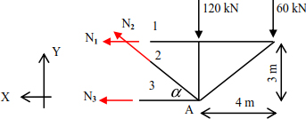
Figure 4.12. Part of the structure proposed
The equilibrium equations of the right portion (Figure 4.12) are:

Knowing that: 

Bars (1) and (2) are tensioned while bar (3) is compressed.
EXAMPLE 4.2.–
Determine the internal forces on bars 1, 2 and 3 (Figure 4.13).

Figure 4.13. Given structure
We cut the truss by a curve as shown in Figure 4.14. The right part is considered for analysis.


Figure 4.14. Part considered

The equilibrium equations of the right portion (Figure 4.15) are:


Figure 4.15. Forces on bars 1, 2, and 3
Hence, 
Knowing that 
Table 4.2 groups the forces on the bars of the truss (Figure 4.13).
Table 4.2. Forces on bars 1, 2 and 3
| Bar | 1 | 2 | 3 |
| Normal force |  |
 |
 |
| Nature of force | Traction | Compression | Compression |
4.5.3. Matrix method
We consider a truss with several bars in Figure 4.16.

Figure 4.16. Portion of a truss
We choose bar (AB) (Figure 4.17).
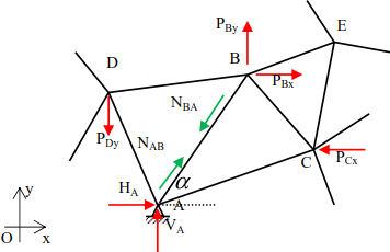
Figure 4.17. Study of bar (AB)
The force in the bar (AB) can be divided into:

lAB, mAB are the components of the unit vector of bar (AB).

Similarly, we can deduce that:

with:


Applying the equilibrium equations to joints A and B allows us to write:


We introduce the equations [4.10] – [4.13] in the relationship [4.14]; the internal forces of the bars can be deduced by:


Knowing that:

The system of equations [4.15] is written as:


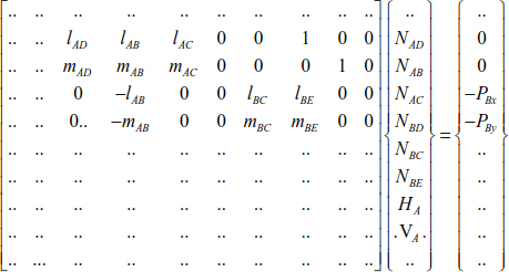
The matrix equation of equilibrium of the bars in the structure is written as:
EXAMPLE 4.3.–
Analyze the structure (Figure 4.18) using the matrix method.

Figure 4.18. Given structure
Joint i

Joint j

Joint k

We can write:

and:

In the matrix form, the previous equations are grouped into:

Resolving the matrix equation leads to determine the internal forces on bars (ij) and (jk), and the support reactions.

The first equation leads to deduce the vertical reaction of support A.

Similarly, the second equation leads to:

Finally, the previous equations lead to determine the vertical reaction.

4.5.4. Graphic or Cremona method
The graphic or Cremona method applies only to internally and externally statically determinate trusses. It describes the method of joint equilibrium in the graphical form.
Method steps
- 1) The intervals between the external forces are numbered in a clockwise direction.
- 2) The intervals between the bars are numbered from left to right.
- 3) The polygon of external forces is established according to a scale of forces. The polygon of external forces forms a closed cycle and its construction is carried out by following the forces in a clockwise direction.
- 4) Likewise, the polygon of internal forces is built around each joint starting with the joint that contains no more than two bars (two unknowns).
- 5) The measurement of the distance between two successive points represents the internal force of the bar defined by these points.
EXAMPLE 4.4.–
Determine the forces on the bars of the truss (Figure 4.19).

Figure 4.19. Given structure
Numbering the intervals between the external forces and the network is shown in Figure 4.20.

Figure 4.20. Numbering of joints and bars
The structure’s external equilibrium leads to the determination of support reactions:

To represent the polygons of external and internal forces, it is necessary to choose a scale of forces; 1 cm on the Cremona diagram is worth 10 kN of force.
Figure 4.21 shows the Cremona diagram, in which the distance between two numbers represents the normal force on the bar separating the regions numbered by these two numbers.

Figure 4.21. Cremona diagram
For example, the internal force in the bar (CB) is the distance between  and
and  .
.
To identify the nature of the internal force, we turn in a clockwise direction around a joint at the end of the bar. Then, the direction of travel from the first joint to the second joint shows the direction of the force relative to the considered joint. We can use joint A as an example (Figure 4.22).
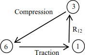
Figure 4.22. Forces around joint 1
The forces on the bars (the force and direction values) are grouped in Table 4.3.
Table 4.3. Forces on the bars
| Bar | AD | AC | DC | DB | BE | CE | BC |
| Distance | 6-1 | 3-6 | 6-7 | 7-1 | 5-8 | 4-8 | 7-8 |
| Force | 75 | 47.43 | 0 | 75 | 10 | 31.62 | 79 |
| Direction | + | – | / | + | – | + | – |
| Nature | Trac. | Comp. | Neutral | Trac. | Comp. | Trac. | Comp. |
4.6. Composite trusses
The method of joint equilibrium or the method of sections can be used to calculate the forces on the bars of a composite truss. In this case, the method of sections is used to determine only a few internal forces. The other forces are calculated by the method of joint equilibrium.
EXAMPLE 4.5.–
Determine the internal forces on the structure (Figure 4.23).

Figure 4.23. Composite structure
Determination of static determinacy
Before calculating support reactions, it is necessary to verify that the truss is statically determinate internally and externally (Figure 4.24).

Figure 4.24. Free-body diagram
The number of support reactions is equal to 3.
The number of equations is also equal to 3.
The structure is statically determinate externally.
The number of bars is b = 19.
The number of equations is 2n – 3 = 2 × 11 – 3 = 19.
The structure is also statically determinate internally.
Finally, the truss (Figure 4.24) is statically determinate internally and externally.
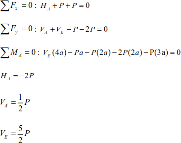
External analysis
In this case, we consider the equilibrium of the whole structure (Figure 4.24).
Calculation of forces on the bars
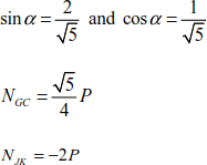
We cut the bars by section (JK), (GC) and (BC) (Figure 4.25).
We apply the static equations:


Figure 4.25. Method of sections
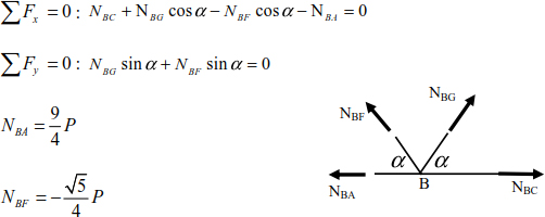
Joint J


Joint G

Joint B
Joint A

Joint E

Joint K

Joint I

Joint D

Joint C

The normal force diagram is shown in Figure 4.26.
Similarly, we have developed a numerical program that calculates the forces on the bars of a statically determinate or statically indeterminate truss. The given structure is modeled (Figure 4.27). The numerical calculation is carried out for the values a = 2 m and P = 1 kN; the numerical results are grouped in Table 4.4.

Figure 4.26. Normal force diagram *
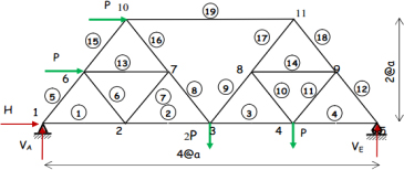
Figure 4.27. Numbering of joints and bars
Table 4.4. Normal force in the bar structure (Figure 4.24)
| Element | Joints | Normal force |
| 1 | 1 2 |
–22,500E+01 0.22500E+01 |
| 2 | 2 3 |
–0.17500E+01 0.17500E+01 |
| 3 | 3 4 |
–0.12500E+01 0.12500E+01 |
| 4 | 4 5 |
–0.12500E+01 0.12500E+01 |
| 5 | 1 6 |
0.55902E+00 –0.55902E+00 |
| 6 | 2 6 |
0.55902E+00 –0.55902E+00 |
| 7 | 2 7 |
–0.55902E+00 0.55902E+00 |
| 8 | 3 7 |
–0.55902E+00 0.55902E+00 |
| 9 | 3 8 |
–0.16771E+01 16,771E+01 |
| 10 | 4 8 |
–0.55902E+00 0.55902E+00 |
| 11 | 4 9 |
–0.55902E+00 0.55902E+00 |
| 12 | 5 9 |
0.27951E+01 –0.27951E+01 |
| 13 | 6 7 |
0.50000E+00 –0.50000E+00 |
| 14 | 8 9 |
0.50000E+00 –0.50000E+00 |
| 15 | 6 10 |
0.11180E+01 –0.11180E+01 |
| 16 | 7 10 |
–0.11180E+01 0.11180E+01 |
| 17 | 8 11 |
–0.22361E+01 0.22361E+01 |
| 18 | 9 11 |
0.22361E+01 –0.22361E+01 |
| 19 | 10 11 |
0.20000E+01 –0.20000E+01 |
4.7. Complex trusses
Complex trusses are those which are not mentioned in the categories of simple or composite trusses. Complex trusses are statically determinate internally and externally, but they cannot be analyzed by the method of joint equilibrium or the method of sections. Figure 4.28 shows this category of trusses.
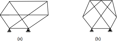
Figure 4.28. Complex structures
Truss (a)
Number of bars, b = 9.
Number of joints, n = 6.
b = 2n – 3, the structure is statically determinate internally.
Number of unknowns, r = 3.
Number of equations, ne = 3.
The structure is externally statically determinate.
Truss (a) is statically determinate internally and externally.
Truss (b)
Number of bars, b = 11.
Number of joints, n = 7.
b = 2n – 3, the structure is statically determinate internally.
Number of unknowns, r = 3.
Number of equations, ne = 3.
The structure is externally statically determinate.
Truss (b) is statically determinate internally and externally.
In trusses (a) and (b), there is no joint containing two bars, which makes it impossible to use the method of joint equilibrium or the method of sections.
As a result, matrix methods offer a very considerable advantage to the analysis of this category of structures. Matrix methods can be used interchangeably with the analysis of trusses without taking into account the static determinacy or static indeterminacy of the given truss.
4.8. Space trusses
A space truss is composed of bars interconnected at the ends, constituting a three-dimensional truss. External forces are always applied to the joints in all three directions. The simplest space truss is a tetrahedron consisting of six bars and four joints (Figure 4.29).
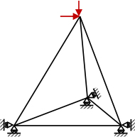
Figure 4.29. Space truss
Internal analysis
In a space truss with n joints, b bars and r support reactions, we can say that the structure is unstable internally if:

The structure is statically determinate internally if:

The structure is statically indeterminate internally if:

The static indeterminacy of a truss is defined by:

External analysis
The equilibrium equations in the three directions are:


Similarly, the bending moments in the direction of the axis are:


The degree of external static indeterminacy can be deduced by:

We can distinguish that the space structure is unstable externally if:
The space structure is statically determinate externally if:

The space structure is statically indeterminate externally if:

4.8.1. Space truss analysis
Analysis methods for plane trusses have been discussed in section 4.5. These methods can be effectively extended to the analysis of space trusses.
For example, the method of joint equilibrium applies in the same way as in the analysis of plane trusses. Equations [4.21] must be satisfied at each joint of the space truss. In general, each joint has three forces or three independent reactions. For this reason, analyzing space trusses starts from the joint having, at most, three unknowns that can be deduced by applying static equations. This approach applies sequentially to each joint of the space truss until all the forces on the bars are determined.
EXAMPLE 4.6.–
The space truss (Figure 4.30) is composed of nine identical bars and is stressed by a nodal force F applied to the free joint in direction (ZZ):
- – calculate support reactions:
- – deduce the forces on the bars.
We isolate the space truss from its supports (Figure 4.31).

Figure 4.30. Spatial truss

Figure 4.31. Free-body diagram
External analysis
The number of support reactions is equal to 6, which are HA, VA, WA, HB, VB and VC.
The number of static equations is equal to 6. The structure is therefore statically determinate externally.
Internal analysis
Number of bars, b = 9.
Number of support reactions, r = 6.
Number of equations, 3n = 3 × 5 = 15.
It is clear that b + r – 3n = 0.
The space truss is statically determinate internally and externally.
Calculation of support reactions
Conventionally, we associate the direction of any action along the positive direction of the axes of reference.
The application of relationships [4.22] and [4.24] can be written as:

The application of relationships [4.21] leads to:
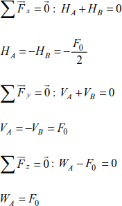
Calculation of forces on the bars
It is necessary to apply the method of joint equilibrium starting with joint B.
Joint B
The equilibrium joint B allows us to write:
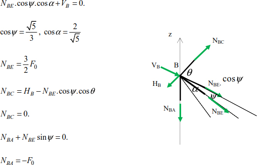
Joint A
The equilibrium equation of joint C leads to:

Joint D
Given that NDA = 0, applying the equilibrium of joint D allows us to write:

Joint C
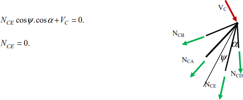
The forces on the bars of the space structure are grouped in Table 4.5.
Table 4.5. Forces in the bars
| Bar | Force | Nature of force |
| AB | –F0 | Compression |
| AC | 0. | Neutral |
| AD | 0. | neutral |
| AE |  |
Compression |
| DE | 0. | Neutral |
| DC | 0. | Neutral |
| BE |  |
Traction |
| BC | 0. | Neutral |
| CE | 0. | Neutral |
The normal force diagram is given in Figure 4.32.

Figure 4.32. Normal force on the bars *(F0)
4.9. Conclusion
A truss is a chain of bars connected to each other at the joints. Its analysis is based on the following assumptions:
- – the bars are biarticulated;
- – the loading system is a set of concentrated forces applied only to the joints;
- – the bars of a truss are stressed by axial forces that can be traction, compression or neutral forces.
The external static indeterminacy of a truss is considered in the same way as that of beams and frames (Chapter 3), whereas the internal static indeterminacy is defined by f = b – (2n – 3), hence:
- b > (2n – 3): the truss is statically indeterminate internally;
- b = (2n – 3): the truss is statically determinate internally;
- b < (2n – 3): the truss is unstable internally.
The forces on the bars of a truss can be deduced by (1) the method of joint equilibrium, (2) the methods of sections, (3) the matrix method, or (4) the graphical method.
In order to analyze composite structures, a combination of the method of joint equilibrium and the methods of sections is generally used.
The principle of the space structure analysis method is applied in the same way as in the analysis of plane trusses. The purpose of analysis methods of trusses is to determine support reactions and internal forces on the bars.
4.10. Problems
Exercise 1
Distinguish statically determinate, statically indeterminate and unstable structures among the following structures:


Exercise 2
Use the method of joint equilibrium to determine the forces on the bars of the following trusses and draw a diagram of internal forces:


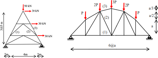
Exercise 3
Using the method of sections, determine the forces on bars (1), (2) and (3) of the following trusses:

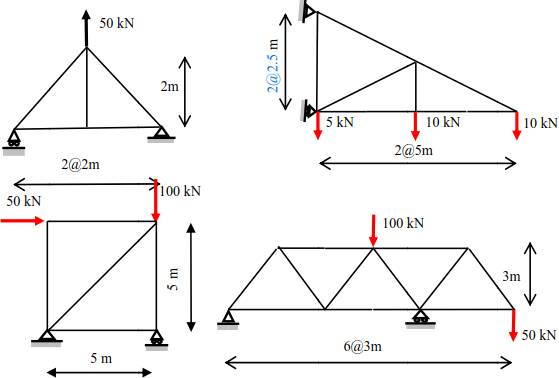
Exercise 4
Using the graphical method, evaluate the value and the direction of each force in the bars of the following trusses:
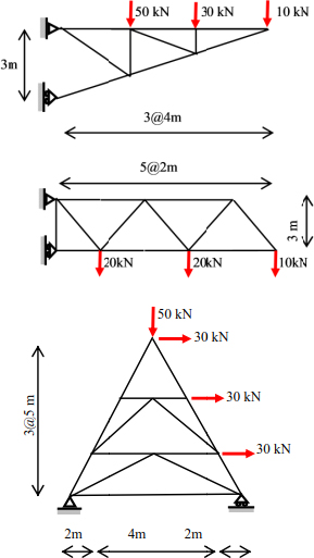
Exercise 5
Using the matrix method, determine the forces on the bars of the following trusses and draw a diagram of internal forces:

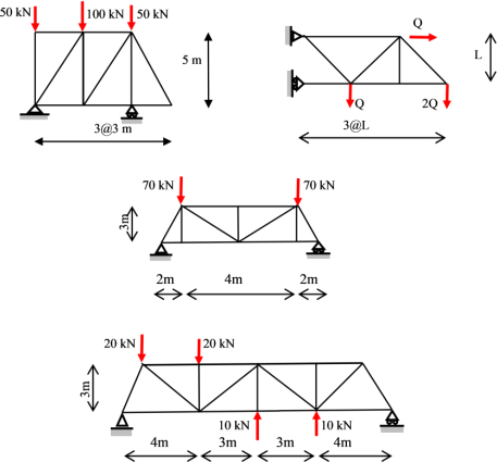
Exercise 6
Determine the forces on the bars of the following trusses and draw their diagrams:


Exercise 7
Determine the forces on the bars of the following trusses and draw their diagrams:


