
Surface texture is used to describe several elements of a machined surface. The major elements of surface texture are roughness, waviness, lays, and flaws, as shown in Figure A4.1. Surface roughness is the tiny irregularities on surfaces, usually of the order of microns. Surface waviness describes a more regular feature of valleys and crests on a surface, usually of the order of millimeters. Surface roughness is superimposed on surface waviness. Lay is used to describe the direction of the predominant surface pattern. Flaw describes any recognizable defect on a surface. Surface texture is generally specified with symbols, as shown in Figure A4.2. Several parameters of surface roughness have been defined, but the most popular is the arithmetic mean average surface roughness height value (Ra). It is in microns (SI units) or is measured in microinches (English units). The control of surface roughness is important for two reasons, namely: To reduce friction and control wear. These two factors influence the service life and performance quality of machines and equipment. The accuracy of measurements is related to the accuracy of the surface because fine resolution cannot be detected on a freehand surface. It is the responsibility of a designer to specify appropriate surface finish for functionality at minimum cost. ANSI B46.1 deals with surface control, and symbols of surface texture are defined in ANSI Y14.36.
A4.1 SURFACE TEXTURE SPECIFICATION
Surface texture may be specified in three ways, namely, full, basic, or general specification. In the full and basic specifications, the surface texture symbol should be placed perpendicular to the edge view of the surface, as indicated in Figure A4.2 and Figure A4.3.
Figure A4.1. Elements of surface texture.

Figure A4.2. Full specification of surface texture.
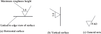
Figure A4.3. Basic specification of surface texture symbol.
A4.1.1 FULL SPECIFICATION
In full specification, parameters of surface texture are indicated on the texture symbol for the referenced surface. Figure A4.2 shows a full specification of surface texture. The labeling is only for understanding; this is not part of a specification.
Only important parameters of surface textures are indicated on the texture symbol for the referenced surface. How many parameters are considered important depends on the designer or engineer. In many situations, the maximum roughness height is all that is indicated in a basic specification, as shown in Figure A4.3 (a) and Figure A4.3 (b). When the maximum roughness value is indicated on a texture symbol, it implies that any value smaller than that shown is acceptable.
A4.1.3 GENERAL SPECIFICATION
Parameters of surface textures are not indicated on the texture symbol for the referenced surface. The surface texture symbol and a note are added to drawing. A note such as FAO (finish all over) is common. Figure A4.3 (c) is an example of a general specification. Figure A4.4 is an example of a component with surface finish specification.
A4.2 SURFACE ROUGHNESS PRODUCTION
Different manufacturing processes have different capabilities for producing surface texture quality. Generally, machining with heavy feeds and slow speeds results in freehand surfaces or high roughness values. Machining with fine feeds and high speeds gives smooth surfaces or low roughness values. Often, a finish machining process is carried out after a freehand machining process in order to achieve a desired surface finish. Table A4.1 summarizes typical roughness height values for some manufacturing processes. Higher or lower roughness values may be obtained under special conditions.

Figure A4.4. Application example.
Table A4.1. Typical surface roughness height for some manufacturing processes
Roughness height, Ra(µm) |
Manufacturing Process(es) |
12.5–1.6 |
Planning, shaping |
6.3–1.6 |
Drilling, milling |
6.3–0.4 |
Boring, turning |
3.2–0.8 |
Broaching, Reaming |
1.6–0.1 |
Grinding |
0.8–0.1 |
Honing |
0.4–0.1 |
Lapping |
0.2–0.25 |
Superfinishing |