
3.1 INTRODUCTION
An auxiliary view is an orthographic view that is created for a feature on an inclined or oblique face of an object. It is created from at least two principal views with the aim of showing the true shape and size of the feature. Conceptually, it is a normal view obtained by looking at a plane in a direction perpendicular to it because the direction of a plane is defined by an axis perpendicular to it. Though there is no limit to the number of auxiliary views that can be generated from principal views, practical considerations restrict views to preferred directions of inclined and oblique faces on objects. Consequently, a limited number of auxiliary views are normally needed in technical graphics. A primary auxiliary view is the first auxiliary view that is obtained from two principal views of an object. A secondary auxiliary view is generated from a primary auxiliary view and one principal view. Third, fourth, and so auxiliary views may be drawn; however, most technical graphic problems can be solved with one or two auxiliary views. Successive auxiliary views are views obtained from one principal view and a primary auxiliary view or from two other auxiliary views. Usually, one auxiliary view can substitute for one of the standard or principal views in a multiview drawing, and thus reduce the total number of views necessary for complete description of a component. Hidden lines appearing behind auxiliary view features are usually not shown for clarity purposes.
3.2 UNDERSTANDING AUXILIARY VIEWS
Auxiliary views are needed when a feature is foreshortened in one or more principal views. Features are foreshortened when they appear on inclined and or oblique faces. Foreshortened images are distorted, so there is always a necessity to clarify such images in technical graphics. Auxiliary view techniques allow us to look directly (perpendicularly) at a face on an object, and hence see the features on it in true shape and size. Therefore the techniques of generating auxiliary views help us correct the distortion of foreshortened images on principal views, though they are often tedious to create manually. However, auxiliary views can be generated easily with Computer Design Drafting (CDD) packages.
In creating auxiliary views, some concepts need to be properly understood. These include the true length (TL) line, edge view of a plane, inclined and oblique planes. A TL line is one whose true size is represented on a view. The edge view of a plane is a line. This is the view of a plane when the view direction is parallel to the plane. Inclined and oblique planes can be recognized by inspecting two adjacent principal views.
Figure 3.1a shows the case of an inclined face where the edge view of the face is shown in one principal (front) view. The face is shown foreshortened in the other two principal views. In Figure 3.1a, two adjacent views are sufficient to identify the face as inclined (front and right or front and top). In a problem with an inclined face, only one primary auxiliary view will be needed to create the true shape and size of a feature on it. Hence, for Figure 3.1a, an auxiliary is required to reveal the true shape of the inclined face. Figure 3.1b shows the case of an oblique face where no edge view of the face is shown in a principal view. That is, the face is shown foreshortened in the three principal views. In Figure 3.1b, a combination of the front and top views or the front and right views is enough to identify the face as oblique because the plane appears foreshortened in either pair. In this case, both primary and secondary auxiliary views would be needed to create the true shape and size of the feature on such a face.
As the form of components gets more complicated, inclined and oblique faces may become part of the features. To create the necessary auxiliary view for the true shape and size of faces and features on them, first identify or create an edge view of the face; then, project the face in a direction perpendicular to the edge view plane. Figure 3.2a shows two adjacent views of a line with endpoints 1 and 2. Point 1 in the front view is indicated by F1 and H1 in the top view. In the front view, the line is horizontal and parallel to the fold line, a reference line between the two views. On the top (horizontal) view, the line is inclined and shows the true length of the line. Hence, a view showing the true length of an inclined line is adjacent to a view that shows the inclined line parallel to a fold line. Fold lines are not always shown in standard orthographic view. They may be safely assumed to be midway in the gap between the adjacent views. Figure 3.2b shows an oblique face with no TL line. To create a TL line, the line F2-F4 is drawn horizontal, parallel to the fold line, and is projected to the top view as H2-H4. The line H2-H4 is the TL line of line F2-F4. The edge view of the oblique face is developed in a primary auxiliary plane with a view direction parallel to line H2-H4. The principle to take note of is that the edge view must be created with a view direction parallel to a TL on the oblique face. In many drawings, TL line can be identified where two faces on an object intersect.
Figure 3.1. Inclined and oblique faces. (a) Inclined face. (b) Oblique face.
In the case of an inclined face, the TL line is the edge view of the face itself as in Figure 3.2a. Hence, the primary auxiliary view derived from the edge view gives the true shape and size for the face and the features on it. If a TL line cannot be identified on an oblique face, one can be created as shown in Figure 3.2b. Once a TL line is available, the edge view of the oblique can be created in a primary auxiliary view with the projection lines parallel to the TL line. The true shape and size of the oblique face and the features on it can then be created in a secondary auxiliary view with the projection lines perpendicular to the edge view line.

Figure 3.2. Identifying or creating a TL line. (a) Inclined face. (b) Oblique face.
3.3 VISUALIZING AUXILIARY VIEWS
3.3.1 AUXILIARY VIEW IMAGE BOX
An image box can be constructed with an auxiliary plane included in the principal image box. The auxiliary plane must be made parallel to the inclined or oblique face in the image box. Figure 3.3a illustrates this concept for an inclined face. The layout of the views in the image box is shown in Figure 3.3b. Note that the right view is omitted in the layout. It is important to maintain the same amount of distance for the nearest point on an image from all the fold lines (edges of the image box) in the layout. Auxiliary views must be aligned with the auxiliary face in layout. Also, all projection lines must be perpendicular to the auxiliary plane. The view direction is always parallel to the projection lines.
3.3.2 FULL AND PARTIAL AUXILIARY VIEWS
Auxiliary views may be created as full or partial views. In a full auxiliary view, all features in the view direction on the object are represented. This means images of both foreshortened and nonforeshortened features on principal views are shown. In many cases, the inclined and oblique faces are portions of a larger component, with some features appearing true shape and size in some standard views. Therefore, the real need is to represent only the foreshortened features on auxiliary views. Hence, partial auxiliary views are most often needed to supplement standard views. In a partial auxiliary view, only the features on an inclined or oblique face are represented on the auxiliary view. This usually leads to a clearer presentation, as additional noninclined or oblique features might actually confuse the view.

Figure 3.3. An auxiliary image box and layout. (a) Image box. (b) Layout.
Figure 3.4. Types of auxiliary views. (a) Full. (b) Partial.
For instance, consider Figure 3.4a that shows a full auxiliary view. It is obvious that the extra details in the auxiliary view of Figure 3.5a are better revealed in the principal views of Figure 3.4a where they appear in true size and shape. Therefore, the partial auxiliary view of Figure 3.4b is preferred. Note that, in the partial auxiliary view of Figure 3.4b, hidden lines have been omitted. This normally enhances clarity of views as can be verified by comparing the partial view of Figure 3.4b with the appropriate portion in the full view in Figure 3.4a. Feature views appearing in true shape and size in principal views are not necessary in auxiliary views, they just complicate drawings.
3.4 CONSTRUCTING AUXILIARY VIEWS
This section discusses techniques for constructing auxiliary views for features on inclined faces and oblique faces. The true size and shape of features on an inclined plane need one auxiliary plane, a primary auxiliary plane for development. However, the true size and shape of features on an oblique plane can the developed with a minimum of two auxiliary planes, namely, a primary auxiliary plane and a secondary auxiliary plane.
3.4.1 CONSTRUCTING FEATURES ON INCLINED FACES
When a feature is on an inclined plane, the edge view of the plane will be revealed in one of the principal views. This view should be chosen as the base view for developing the auxiliary view that will show the true shape of the feature. As the auxiliary view is created from a principal view, it is a primary auxiliary view. The steps to employ in constructing the auxiliary view are outlined as follows.
3.4.1.1 Step 1: Create Two Principal Adjacent Views
Create two adjacent principal or standard views. All the features on the two views need not be completed in order to proceed to the auxiliary view. One of the standard views should show the edge view (line) of the inclined face as in Figure 3.5. Identify this view as the base view (front view in Figure 3.5) for auxiliary view creation.
3.4.1.2 Step 2: Draw Projection Lines for Auxiliary View
Identity the vertices of the face and use them to draw projection lines. In Figure 3.6, the vertices of the face are the two endpoints of the inclined line or edge view of the face. Key points on features on the face may be used also in drawing projection lines. The key points on the circular feature are the edges and the centerline of the hole. Draw projection lines from the identified vertices and key points perpendicular to the face as shown in Figure 3.6. A fold line may be drawn and used as a reference line for the transfer of dimensions between adjacent views. A fold line must be parallel to the edge view of the inclined face at a convenient distance. A fold line is not shown in Figure 3.6.

Figure 3.5. Two principal views.
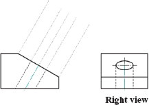
Figure 3.6. Projection lines for auxiliary view.
3.4.1.3 Step 3: Draw the Outline of the Inclined Face
Establish the distance of each vertex on the auxiliary view from the adjacent principal view (right view in Figure 3.6) to the base view. Transfer the distance of each vertex to the auxiliary view, and draw the outline of the inclined face. Figure 3.7 shows the construction of the inclined face outline.
3.4.1.4 Step 4: Draw the Feature on the Inclined Face
Establish the distance of key points of the feature on the inclined face (K2, K2, and K3 in the right view of Figure 3.8) from the adjacent principal view to the base view. In this example, these are two horizontal quadrants on the ellipse on the right view and the centerline of the hole. Transfer the distance of each key point to the auxiliary view and draw the feature. Figure 3.8 shows the construction of the circle feature on the auxiliary view. It is very important that the principle of size transfer be properly understood: transfer size from the second view prior to the current auxiliary view.
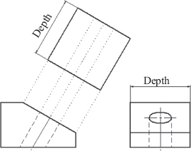
Figure 3.7. Draw outline of face.
Figure 3.8. Draw the feature.
3.4.2 CONSTRUCTING FEATURES ON OBLIQUE FACES
Sometimes, a feature may lie on an oblique face. In this case, both a primary and a secondary auxiliary view will be needed to establish the true shape and size of the face and the features on it. The primary auxiliary view is used to develop the edge view of the face, and the secondary auxiliary view shows the true shape and size of the face and feature(s). The steps to solve this problem are:
3.4.2.1 Step 1: Create Two Principal Views
In Figure 3.9, two adjacent principal or standard views are created. Again, the full views need not be created in order to construct the auxiliary views. It may, in fact, be necessary to criss-cross between the principal and auxiliary views during the development. Remember that none of these principal views will show the edge view of the oblique face. Some judgment is needed in selecting elements that can reduce time and effort in the construction process. This comes with practice and experience.
3.4.2.2 Step 2: Identify a Line Element of TL on the Oblique Face in the Base View
If no line can be identified as of a TL on the oblique face on any view, then create a horizontal line on the oblique face in one principal view, draw the TL of this line in the adjacent principal view; Figure 3.2 gives more information on creating a TL line. Choose the view with the TL line as a base view. In Figure 3.9, we can identify a TL line on the oblique face in the top view as indicated in Figure 3.10. This is the front edge between the top face and the oblique face. Hence, the base view for auxiliary views creation is the top view in Figure 3.9.

Figure 3.9. Principal views.
3.4.2.3 Step 3: Draw Projection Lines for Primary Auxiliary View
Identify the vertices of the oblique face and use them to draw the projection lines. In Figure 3.9, the vertices of the face are the endpoints of the base line (points K1 and K2 in Figure 3.10) and the top line on the front end of the oblique face (points K3 and K4 in Figure 3.10). The key points K5 and K6 are identified for the projection of object thickness. Draw projection lines from the identified vertices parallel to the TL line element, see Figure 3.10. Note that all projection lines must be parallel to each other.
Figure 3.10. TL line and projection lines.
3.4.2.4 Step 4: Draw the Edge View
A reference or fold line may be drawn and used for the transfer of dimensions between adjacent views. A fold line must be perpendicular to projection lines, see Figure 3.11. Once the reference line is drawn, the edge can then be created by transferring dimensions of key points or vertices from two views behind as explained earlier. It is sufficient to draw only the lines of the edge views without adding thickness sizes. In Figure 3.11, the material thicknesses of the two faces have been added. These dimensions could have been omitted without loss of accuracy. This view is the primary auxiliary view that shows the edge view of the oblique face.

Figure 3.11. Reference line and edge view.
3.4.2.5 Step 5: Draw Projection Lines for Secondary Auxiliary View
From the vertices and key points on the edge view, draw projection lines for the secondary auxiliary view. These projection lines must be perpendicular to the edge view line. This step is shown in Figure 3.12.
3.4.2.6 Step 6: Draw the Outline of the Oblique Face
Establish the distance of each vertex on the oblique face from the base view in Figure 3.9. Transfer the distance of each vertex to the auxiliary view and draw the outline of the oblique face as shown in Figure 3.13.

Figure 3.12. Projection from edge view.
Figure 3.13. Draw outline of an oblique face.
3.4.2.7 Step 7: Draw the Feature(s) on an Oblique Face
Establish the distance of each key point on feature(s) on the oblique face from the baseview in Figure 3.9. Transfer the distance of each key point to the secondary auxiliary view and draw the feature(s) as shown in Figure 3.14.

Figure 3.14. Draw feature(s) on an oblique face.
3.5 GENERATING AUXILIARY VIEWS FROM SOLID MODELS
Creating auxiliary views is less cumbersome with solid models using CDD packages. The shapes of inclined and oblique faces and the features on them present little difficulty with solid models. Most modern CDD packages with solid modeling capability include routines that can be used to create auxiliary views easily from solid models. The details in the process of creating auxiliary views vary with each CDD product. In most cases, creating an auxiliary view for an inclined face is a one-or two-step process, while creating an auxiliary view for an oblique face is a two- or three-step process after the base views are created or identified.
The concept of planes and faces should be properly understood when dealing with solids. A plane is a flat surface of infinite length and width. A face is a surface on an object and may be flat or curved. A cylindrical face on a pipe is curved surface, for example. A flat face is a portion of an imaginary flat plane. Auxiliary views are generated from flat planes by CDD packages. The user must specify a plane when creating an auxiliary view. CDD software creates full auxiliary and partial views depending on the length of the cutting plane defined. Some dressing of the auxiliary view may be needed. The view direction is assumed to be perpendicular to the plane that is selected when generating the auxiliary view.
3.5.1 GENERATING AUXILIARY VIEWS FOR AN INCLINED FACE
As an illustration, we will revisit Figure 3.5 in discussing the technique for generating an auxiliary view for an inclined face. Care is needed when selecting the auxiliary plane; it must be perpendicular to the view direction. Solid Edge package was used in this example.
3.5.1.1 Step 1: Create Two Standard Views
First, generate two adjacent principal views from the solid model as shown in Figure 3.15. Identify the base view as the principal view showing the edge view of the face. In this example, the front view is the base view, while the left view is the adjacent principal view.
Figure 3.15. Principal views.

Figure 3.16. Full auxiliary view.
3.5.1.2 Step 2: Select the Auxiliary View Button
In some CDD packages, a command might be needed to invoke the auxiliary view routine. In many cases, a button is available in the paper space environment that can be selected to invoke the auxiliary view routine. Once this routine is active, it will request the user to select the plane for the desired auxiliary view. In Figure 3.16, the plane of interest is indicated. The line segment of the face was selected as a line feature on the plane.
3.5.1.3 Step 3: Place the Auxiliary View
With the plane selected, the routine requests the user to select a position for the auxiliary view. Drag the cursor to a convenient position and click to place the view. In Figure 3.16, the view direction is indicated, but this was generated by the software. The full auxiliary view created by the software is shown. The inclined face will show on the view. Likewise, all the features on the face will show.
3.5.2 GENERATING AUXILIARY VIEWS FOR AN OBLIQUE FACE
As an illustration, we will revisit Figure 3.9 in discussing the technique for generating an auxiliary view for an oblique face.
3.5.2.1 Step 1: Create Two Standard Views
As in the inclined face problem, generate two adjacent principal views from the solid model as shown in Figure 3.17. Identify the base view as the principal view showing a TL element. If no TL element is found on a principal view, one must be created. In this example, the top view is the base view, while the front view is the adjacent principal view.
3.5.2.2 Step 2: Define Primary Auxiliary Plane
Once a TL is identified, see Figure 3.18, the primary auxiliary plane can be defined. This plane must be perpendicular to the TL element. If no such line exists on the base view, then one must be created. In Figure 3.18, the primary auxiliary plane is indicated in the top (base) view.

Figure 3.17. Standard view.
Figure 3.18. Edge view from base view.
3.5.2.3 Step 3: Create the Primary Auxiliary View.
Invoke the auxiliary view routine either with a command or by selecting a button. The routine will request the user to select the plane for the desired auxiliary view, so select the plane accordingly. With the plane selected, the routine requests the user to select a position for the auxiliary view. Drag the cursor to a convenient position and click to place the view as shown in Figure 3.18. A full auxiliary edge view should be created by the software.
3.5.2.4 Step 4: Define the Secondary Auxiliary Plane.
With the edge view line as a TL element, use the same procedure as explained in Step 2 to define the secondary auxiliary plane. Figure 3.19 illustrates this step.
3.5.2.5 Step 5: Create the Secondary Auxiliary View.
Invoke the auxiliary view routine either with a command or by selecting a button. Then, select the secondary auxiliary plane. Next, place the view in position by dragging the cursor to a convenient position and click. A full secondary auxiliary view should be created by the software as shown in Figure 3.19. The oblique face will show on the view. Likewise, all the features on the face will show. As can be noticed, centerlines and center marks are not automatically added to auxiliary views generated from solid models by some packages. These must be added as desired in standard drafting practice. These features were added in the two examples (Figure 3.16 and Figure 3.19).

Figure 3.19. Full auxiliary view for an oblique face.
3.6 COMBINED STANDARD AND PARTIAL AUXILIARY VIEWS
When constructing views for a drawing, time and effort can be saved by use of partial auxiliary and standard views. For example, consider Figure 3.20 in which two standard views (top and right) are shown as partial views. Also, the auxiliary view is shown as a partial view. Thus, three partial orthographic views and one full standard (front) view can adequately convey the necessary shape and dimensional information about the component. If a solid model is not available, so that the views are drawn from a sketch or isometric drawing, a lot of time and effort will be saved drawing the partial views instead of the full views for the four necessary views. The isometric insert is added in Figure 3.20 to aid visualization. The use of partial views should be kept in mind by design drafters, as productivity is an important concern for supervisors and employers. If views are generated from solid models, the standard views obtained will always be full views. These standard views may be converted to partial views by modifying then manually. However, some CDD packages allow partial auxiliary views to be created from solid models by defining an edge view length that spans only the portion of interest.
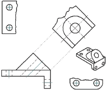
Figure 3.20. Partial auxiliary and standard views.
3.7 CHAPTER REVIEW QUESTIONS
1. What is an auxiliary view?
2. Why are auxiliary views sometimes necessary?
3. Define incline plane and oblique planes.
4. What is the minimum auxiliary view(s) for an object with an inclined face?
5. What is the minimum auxiliary view(s) for an object with an oblique face?
6. Define the following:
(a) TL of a line.
(b) Edge view of a plane.
(c) Primary auxiliary view.
(d) Successive auxiliary view.
7. What are full and partial auxiliary views?
8. When is a partial auxiliary view helpful?
Create standard and auxiliary views for each of the following figures. All the figures, except the last, will need at least one auxiliary view. The last figure needs more than one auxiliary view.

Figure P3.1. Problem 1.

Figure P3.2. Problem 2.
Figure P3.3. Problem 3.

Figure P3.4. Problem 4.
Figure P3.5. Problem 5.
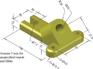
Figure P3.6. Problem 6.
Figure P3.7. Problem 7.


