4.1 INTRODUCTION
A section view is an orthographic projection view drawn to reveal internal or hidden features in an object. Section views are used to supplement standard orthographic view drawings in order to completely describe an object. They improve visualization of designs, clarify multiviews, and facilitate dimensioning of drawings. Hence, they are an important aspect of design and documentation. Section views are created by defining an imaginary cutting plane or planes on the object, so that the observer can see the internal details. Hidden lines are generally not shown in sections. Hatch lines (also called section lines) are used to indicate solid materials that are cut through. A hatch pattern has certain attributes, such as orientation and line spacing, which are used to represent specific materials or group of materials. Both part and assembly sections can be created. Sometimes, auxiliary section views may be needed for clarity.
4.2 CONCEPT OF SECTIONS
In an orthographic projection, the standard projection planes are top (horizontal), front (frontal), and side (profile). The frontal and profile planes are vertical, while the top is horizontal. Standard drawing views are created on these planes with preferred view directions. The view direction for the frontal and profile planes is horizontal, while the view direction for the horizontal plane is vertical. Figure 4.1a shows the standard front and top views of a cylinder. Figure 4.1b shows the same cylinder in mixed (standard, section, cut isometric) views, with the front view converted to a section view. Several elements associated with the concept of sections are indicated in Figure 4.1b. These are (i) cutting plane line, (ii) view direction, (iii) removed portion, (iv) retained portion, (v) hatching, and (vi) section caption or label.
Figure 4.1. Concept of sections. (a) Standard views. (b) Mixed views.
The cutting plane is an imaginary plane that passes through the object at a position of interest. It is represented by a line (the edge view of the section plane) in an adjacent view to the section view. In Figure 4.1b, the cutting plane is vertical because its edge view is seen on the horizontal plane. Cutting planes can change direction within an object. The view direction is the line of sight or the direction an imaginary viewer is facing. The view direction is indicated by the arrow head and is perpendicular to the cutting plane. In Figure 4.1b, the view direction is horizontal. The removed portion is the portion of an object that is assumed to have been removed in order to expose the interior. It is the cut-out portion of the object. The viewer is able to directly see the interior of the object when the cut-out is removed.
The retained portion is the portion of an object that is assumed to be left in front of the viewer. The hatching is the pattern of hatch lines used to indicate solid material. The section label is the name given to the section or cutting plane. A very important difference between standard and section views is the replacement of hidden lines in standard views with visible lines in section views. This is very fundamental since it indicates the feature is now visible in a section view. Comparing the standard and mixed views of Figure 4.1 shows the clarity advantage of section views. Another advantage of section views is that the visible lines from hidden lines in standard views can be used for dimensioning; hidden lines are not used for dimensioning. When parts or assemblies have complex internal features, hidden lines in standard views become confusing, sections are then indispensable.
A cutting plane is represented by a line that shows the edge view of the cutting plane. A limited number of line styles are used to represent cutting planes. In Figure 4.2, the common line styles for cutting planes are shown. They are (a) thick centerline, (b) thick phantom line, and (c) broken visible line. The representation in (c) is used if the cutting plane line would hide important details in a drawing. Each of these lines is usually joined to an arrow at each end. The direction of the arrow is the viewer’s line of sight. Cutting plane lines are drawn in the view adjacent to the section view and may go beyond the boundary of the adjacent view. The thickness of a cutting plane line should be more than that of normal visible line.
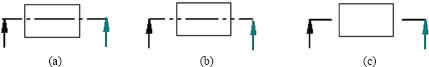
Figure 4.2. Cutting plane line styles. (a) Thick centerline. (b) Thick phantom line. (c) Broken visible line.
4.4 HATCH PATTERNS
Hatch lines are thin lines, and when they are laid out in a specific angle and spacing, a hatch pattern is formed. A hatch pattern is always within a closed boundary. If there is a gap in a section, hatching will not occur when using CDD systems. Spacing of hatch lines should enhance readability. Depending on the size of the drawing, it may be between 1.5 mm (0.06 in) and 6 mm (0.25 in) in relatively small drawings. Likewise, the inclination of hatch lines should be guided by clarity. The angle of inclination for hatch lines normally varies between 15° and 75°. Popular angles are 15°, 30°, 45°, 60°, and 75°. The angle 45° is the default angle in most CDD software. Hatch lines must not be drawn or placed parallel to object lines or features in a section. In Figure 4.3, the left column views have hatch lines parallel to some object features, and they are, therefore, unacceptable. The acceptable representations are shown in the right column views. The angle of inclination of the hatch lines must be different from the angles of inclination of all the features forming the boundary of a hatch pattern. Figure 4.4 shows some examples of assembly hatch patterns. When components are assembled, the hatch patterns must not be parallel to object lines or features of hatch boundary. Also, hatch lines are inclined at different angles in each component in order to distinguish them.
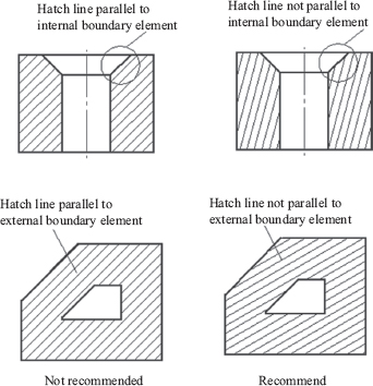
Figure 4.3. Hatch pattern layout.

Figure 4.4. Assembly hatch patterns.
Figure 4.5. (a) Material type hatch patterns. (b) Material type hatch patterns.
Conventionally, some hatch patterns are associated with specific materials and Figure 4.5 shows some material hatch pattern types. However, the proliferation of available materials today makes it impractical to have a unique hatch pattern for material types and grades. Thus, selected material hatch patterns are in common use. In architectural drawings, some material hatch patterns are in popular use. Machine drawings use few material hatch patterns, and ANSI 31 pattern for cast iron in Figure 4.5 is the recommended pattern for machine drawings. This pattern may be used for all types of materials in machine drawings.
4.5 SECTION VIEW REPRESENTATION AND PLACEMENT
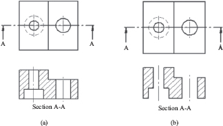
Proper representation of section features is very important. Every feature directly exposed to the viewer needs to be included as visible entities in the section view. Gaps between feature segments must not be allowed. In Figure 4.6, two section view representations are given. The left representation is right, while the right representation is wrong because of gaps between the view segments. The line features omitted in the right representation are clearly visible in the indicated section plane.
The section view position in a drawing has a definite relationship with the view direction. A section view should be placed behind the tail end of the view direction arrow. Figure 4.7 illustrates the application of this principle for (a) top section view, (b) front section view, and (c) right section view. Sufficient gap should be allowed between the section and the adjacent view it is derived from. This gap is very important because sufficient space must be made available for dimension placement.
Figure 4.6. Section view representation. (a) Right. (b) Wrong.

Figure 4.7. Placement of section views. (a) Top section view. (b) Front section view. (c) Right section view.
4.6 SECTION VIEW TYPES
Section views may be classified in different ways. For our discussions, we shall group them into full, partial, and special section views. In full section views, the full length of the principal dimension perpendicular to the view direction of the object is shown in a section view. Hence, the cutting plane or planes pass through the whole cross-section of the object. Partial section views do not reveal the whole sections, but show a portion of the interior. Special sections include auxiliary sections, assembly sections, and un-sectioned features.
4.6.1 FULL SECTION VIEWS
Full section views provide section views along the full length of the cross-section of an object and include straight, offset, removed, revolved, and aligned section views.
A straight section is also called a full section by some authors. The cutting plane for a straight sections cuts right through the middle of the object, so that one half of it is revealed after the second half is imagined removed. Thus, a straight section is created from a single cutting plane. Straight sections are best for objects with an axis of symmetry. In multiview drawings, a section view can replace a standard view, and straight sections are commonly, thus, employed. Figure 4.8 shows an example of a straight section view.
4.6.3 OFFSET SECTIONS
Offset sections are similar to straight sections, except that the cutting plane changes direction at 90° at a time as it goes through the entire object. Offset sections have two or more parallel cutting planes. They are used for complex part with a number of important features that do not lie on the same plane. Figure 4.9 is an example of an offset section view with three cutting planes offset from one another. Note that, in the section view, the offset cutting planes appear collinear. Multiple offset sections are possible in irregular objects.
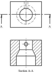
Figure 4.8. Straight section view.
Figure 4.9. Offset section view.
4.6.4 REMOVED SECTIONS
Removed sections are full section views placed at a convenient position from the adjacent view, but linked with the cutting plane either by a line or view label as shown in Figure 4.10. They are displaced from the normal view position and do not need to be of the same scale as the adjacent view they are derived from. If the scale for the removed view is different from the adjacent view, it should be indicated as a local note. It is convenient to display different removed section views along the length of an object if it has varying cross-sections in that direction; see Figure 4.10.
4.6.5 REVOLVED SECTIONS
A revolved section is similar to a removed section, except that the section view is superimposed on the cutting plane after the section has been rotated through 90°. The axis of revolution is indicated with a centerline as shown in Figure 4.11. This representation is attractive when space constraint is an issue. The section view scale is the same as the standard view. The section views can be placed with or without breaking the visible lines adjacent to them on the standard view. Feature lines from the standard view within the revolved view should be removed completely. Revolved section views should be drawn as seen from the view direction. Sections of bars, lever arms, spokes, and other elongated objects are commonly represented in revolved section view.
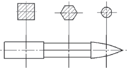
Figure 4.10. Removed section views.
Figure 4.11. Revolved section views.
4.6.6 ALIGNED SECTIONS
In aligned sections, the cutting planes are not parallel, but inclined at some angle. The line of intersection is usually at the center of the object. Like offset sections, the cutting planes are made to pass through features of interest as shown in Figure 4.12. In the section view representation, one of the planes is rotated through some angle to align it with the other, as indicated in Figure 4.12a. The feature is then projected on the aligned plane. This forced alignment makes the section view looks pleasing and easier to visualize. Practical considerations or conventional rules, thus, override strict projection principles in aligned section views.

Figure 4.12. Aligned section views. (a) Component with arms. (b) Component without arms.
Partial section views provide section views of a portion of an object and include half, broken, and detail section views.
4.6.8 HALF SECTION VIEWS
Half sections have two cutting planes that are at 90°, allowing a quarter of the object to be imagined removed. A centerline is used to demarcate the sectioned portion from the un-sectioned portion in the section view as shown in Figure 4.13. Sometimes, hidden lines are shown on the unsectioned part. Half sections are best for objects with two axes of symmetry.
4.6.9 BROKEN SECTION VIEWS
A broken section is a section exposed by a cutout of a portion of an object as shown in Figure 4.14. A brake line is used to show the boundary between the sectioned and un-sectioned portion of the drawing. A cutting plane is not shown in a broken section. A broken section is used to limit the area of interest in an object. It saves time and could substitute for full or half section.
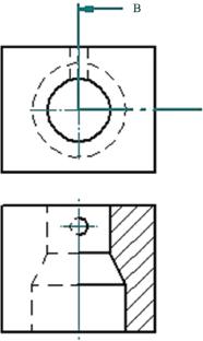
Figure 4.13. Half section.
Figure 4.14. Broken section.
4.6.10 DETAIL SECTION VIEWS
A detail section view is similar to a broken section view, except that it is positioned outside the standard view. Also, it is usually of enlarged scale so as to reveal greater detail around the area of interest in the object. This gives more clarity, and it is often easier to place dimensions on detail section views. Figure 4.15 shows a detail view of a keyway.
4.6.11 SPECIAL SECTION VIEWS
Section views derived from nonprincipal views such as auxiliary sections may be considered as special section views, as they are obtained by applying sectioning rules. Similarly, special application section views such as assembly sections and features or parts that are not sectioned in drawings by convention are special section views.
4.6.12 AUXILIARY SECTIONS
Auxiliary views (full or partial) may be sectioned, and standard conventions apply to them. For example, the section view should be placed on the tail end side of the view direction arrow, and there should be a visible gap between the section view and adjacent standard view. A hatch pattern should be placed with care because the auxiliary view is inclined in position, and hatch lines must not be parallel to boundary line features. Figure 4.16 shows an example of an auxiliary section view.
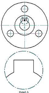
Figure 4.15. Detail section view.

Figure 4.16. Auxiliary section view.
Assembly sections are section views with more than one component shown in their relative fitted positions. They are very useful in checking clashes or interferences of adjacent components in a unit. Adjacent components in an assembly section are hatched at different angles to clarify a drawing. Components are usually numbered and a bill of materials (BOM) or parts list is attached to the drawing. Figure 4.17 is an example of an assembly (full) section view, but without a parts list. Assembly sections may be full or half section orthographic or pictorial views of the unit or product.
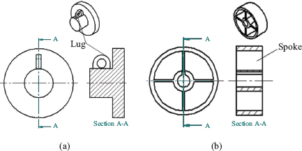
4.6.14 UN-SECTIONED FEATURES
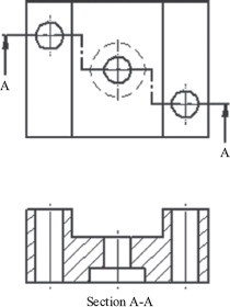
Some features are not hatched in section views if the cutting plane is parallel to their axes. Such features are normally thin and include ribs, webs, lugs, and spokes. However, if the cutting plane is perpendicular to their axes, they may be hatched. Figure 4.18 shows the cutting planes are parallel to a lug and spokes. In a section view, these features are un-hatched because of this parallel geometric relationship. In Figure 4.19, the cutting planes are parallel to a rib and web in the A-A section views, and the rib and wed are un-hatched or un-sectioned. The cutting planes for the B-B sections are defined perpendicular to the rib and web. In this case, the rib and web are hatched or sectioned because of the perpendicular geometric relationship. Figure 4.20 shows a shaft, key, bolt, and nut in section. By convention, these components are not hatched as indicated. Some other standard parts or components not hatched in section views include pins, dowels, fasteners, gears, bearings, and springs.

Figure 4.17. Assembly section view.
Figure 4.18. Un-sectioned features.
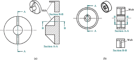
Figure 4.19. Hatching un-sectioned features.

Figure 4.20. Un-sectioned parts.
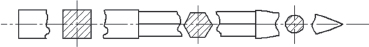
When objects are long and of constant cross-section, their length may be reduced with break lines. Break lines are effective in saving time and space. They allow the scale of a drawing to be increased. Figure 4.21 shows examples of conventional break lines.

Figure 4.21. Break lines for different shapes and materials.
4.8 CONSTRUCTING SECTION VIEWS
In the following discussion, two illustrative examples for constructing section views are considered. This is because, creating the different types of section view with constructional techniques follow the same basic procedure. This procedure has the following steps: Step 1: Create standard view(s); Step 2: Create section plane line(s) and features; and Step 3: Hatch section and finish the drawing.
4.8.1 CONSTRUCTING A STRAIGHT SECTION
Figure 4.22 shows the three-step procedure applied in the construction of a straight section view.
Step 1: Create a standard view.
Using the techniques discussed in Chapter 2 for standard orthographic view creation, create one or two standard views as necessary. After creating the necessary standard views, the outline of the section view is then created as shown in Step 1 of Figure 4.22. Centerlines may be omitted at this stage, but it is recommended that they should be included.
Step 2: Create section plane line and features.
Choose a section plane line style and use it to define the section plane. Using projection lines as shown in Step 2 of Figure 4.22, project the features on the section plane from the top view to the section view. Remember that hidden lines change to visible lines in section view.
Step 3: Hatch section and finish drawing.
Apply the hatch lines to the section and make sure they are properly inclined. Then, check and ensure that centerlines are placed correctly. Check and correct any error. Add a section label.
4.8.2 CONSTRUCTING AN ALIGNED SECTION
Figure 4.23 shows the three-step procedure applied in the construction of an aligned section view.
Step 1: Create standard view.
Create standard views as necessary. The section view outline is then created as shown in Step 1 of Figure 4.23.

Figure 4.22. Constructing a regular section.
Figure 4.23. Constructing an aligned section.
Step 2: Create section plane line and features.
Using projection lines as shown in Step 2 of Figure 4.23, project key points on the features of the lower right arm to the vertical centerline. The base of the slot and the tip of the arm are the necessary key points in this case. Then, transfer the projected points to the center vertical line to the section view. Remember that hidden lines change to visible lines in section view.
Step 3: Hatch section and finish drawing.
Apply the hatch lines to the section and make sure they are properly inclined. Then, check and ensure that centerlines are placed correctly. Check and correct any error. Add a section label.
4.9 GENERATING SECTION VIEWS FROM SOLIDS
Creating section views from solid models is quite straightforward. The routine for creating sections assumes that the user has a standard view on screen. The next step is to create the cutting plane line, and this is most often a step of its own. Then, the user may be prompted to place the view or may terminate the step for the cutting plane and activate another button or initiate another command to place the view. Centerlines are most often added to view on a separate step, and the inclination of the hatch lines may have to be adjusted. Figure 4.24 shows the three-step procedure applied in the generation of an aligned section view.
Step 1: Create a standard view.
Create standard views as necessary, as shown in Step 1 of Figure 4.23 using the routine for orthographic view generation.
Step 2: Create section plane line.
Using the CDD routine for the cutting plane line creation, define the cutting plane as shown in Step 2 of Figure 4.24. Some CDD package gives the direct projection for aligned section. This must be manually corrected to conform to conventions in section views.
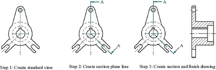
Figure 4.24. Generating a section from solid model (Section A-A).
Step 3: Hatch section and finish drawing.
Check the hatch lines of the section and make sure they are properly inclined. The inclination may have to be adjusted for satisfactory result. Then, check and ensure that centerlines and section label are placed correctly. Check and correct any error.
4.10 CHAPTER REVIEW QUESTIONS
1. What is a section view?
2. What are the advantages of section views?
3. What is a cutting plane?
4. Are hidden lines normally shown in section views?
5. What is the importance of the viewing direction in section views?
6. What is a hatch pattern? How do you differentiate hatch patterns in section views?
7. Sketch the hatch pattern for cast iron and concrete.
8. List the common types of section views discussed in the chapter.
9. How is a removed section view different from a revolved section view?
10. How is an aligned section view different from a revolved section view?
11. How is a broken section view different from a detail section view?
12. How is a straight section view different from an offset section view?
13. What is the advantage of half section view over straight section view?
14. List three types of objects that hatching may not be applied in section view.
15. Where would you consider an auxiliary section view?
4.11 CHAPTER EXERCISES
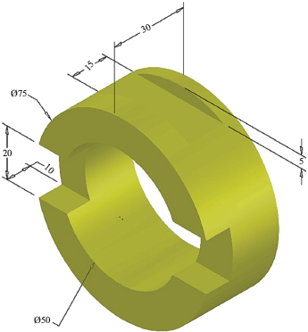
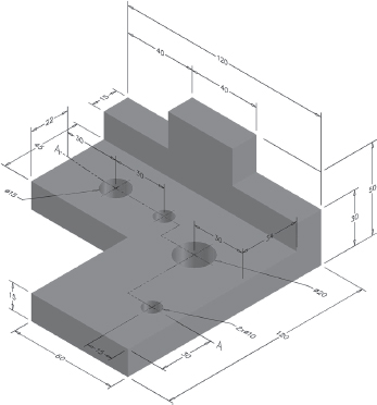
Create standard and section views for the following figures. Ensure that the type of section view chosen is appropriate for each figure.

Figure P4.1. Problem 1.
Figure P4.2. Problem 2.

Figure P4.3. Problem 3.
Figure P4.4. Problem 4.

Figure P4.5. Problem 5.
Figure P4.6. Problem 6.
Figure P4.7. Problem 7.