5.1 INTRODUCTION
Dimensioning refers to the addition of size values to drawing entities. Dimensions are required for points, lines, arcs, circles, and so on, which are related functionally or control relationship of other features. Basic dimensioning is the addition of functional or design and nominal sizes to features on drawing views. This is probably good only for sketches and preliminary design drawings because tolerances are additionally required in working drawings. Most CDD software can automatically add basic dimensions to a drawing. But, some fine-tuning would normally be necessary to achieve acceptable results. ANSI/ASME Y14.5M is the standard for dimensioning practice in the United States. Students should familiarize themselves with this standard; even though the main guidelines are incorporated in the discussions that follow from a practical perspective.
A technical drawing consists of images and annotations of an object arranged in a prescribed order. We may distinguish between engineering diagrams and drawings. Engineering diagrams have views that may be a combination of pictorial view, standard orthographic views, auxiliary views, and section views with hidden lines and centerlines, but without or with incomplete dimensions. Engineering drawings are obtained by adding dimensions, tolerances, and notes to engineering diagrams. Engineering diagrams are normally created manually before dimensions are added to them in traditional drafting. In CDD environments, they can be constructed or generated from 3D models. If generated from 3D models, hidden lines will be shown by most CDD packages, but some may not show centerlines. The user then would have to add centerlines and hidden lines if not already added to the generated views in order to create engineering diagrams. Fortunately, routines or commands are normally available in these CDD packages for adding centerlines or hidden lines automatically in a separate step.
5.2 ENGINEERING DRAWING AND SIZE DESCRIPTIONS
An engineering drawing is a precise technical graphic model that communicates design intent. It is used by manufacturers to make a product and inspectors to determine whether the product should be accepted. An engineering drawing should convey the following information:
• Shape or geometric characteristics of component (drawing views).
• Overall size of component and its features.
• Tolerances on sizes.
• Material for the component.
• Specifications or notes for requirements such as heat treatment, surface finish, and so forth.
Dimensions in engineering drawings are shown in units of length and angle. The standard unit of length in SI system is the meter. In drawing practice, the preferred SI unit of length is the millimeter. One meter (1 m) is equal to one thousand millimeters (1,000 mm). Fractions in dimensions are not allowed in metric drawings; only decimal values are allowed. Architectural drawings may be dimensioned in millimeter (mm) and meters (m). Meters and kilometers (km) are used for civil dimensioning.
Angle refers to the relative orientation of lines on a plane or the relative orientation of planes in space. Angle is conventionally measured in degrees (°). There are 360 degrees in a circle; 60 minutes in a degree; and 60 seconds in a minute. The degree is the common unit of angular measure in metric and English drawings.
5.2.1 DEFINITIONS
• A dimension is a number in a standard unit of measure shown on a drawing to indicate size, location, or orientation of graphic features.
• A design size is the functional size of an object and is equal to the full-size value of the object.
• A plot or print size is the actual size of a graphic entity on a physical drawing sheet.
• Tolerances are small variations permitted on functional sizes for ease of manufacture.
• Actual size is the size of a manufactured object obtained through measurements.
Note that only design sizes are shown as dimensions in engineering drawings. Plot sizes are not shown, but a scale factor is usually indicated on the drawing. The scale factor is the ratio between the design size and the plot size. Tolerances are required for manufacturing convenience because some errors must be accommodated during manufacturing and are usually in the one-hundredths and one-thousandths of functional sizes.
5.3 DIMENSION ELEMENTS AND SYMBOLS
Figure 5.1a shows several elements that define a dimension in engineering drawings. These elements are:
1. Graphic feature (line in Figure 5.1a)
2. Extension line
3. Dimension line terminator
4. Dimension line
5. Dimension value (number)
6. Visible gap
Figure 5.1. Dimensional elements and terminators. (a) Elements of a dimension. (b) Dimension line terminators.
The graphic feature in Figure 5.1a represents a dimensional entity in a view of a drawing. It may be a line, arc, circle, fillet, and so on. The extension line connects the object feature with the dimension line. Sometimes, leaders are used in place of extension and dimension lines, especially when dimensioning arcs and circles.
The dimension line terminators indicate the limits of a dimension. They occur in pairs, one at each end of the dimension line. It is a filled arrow in this figure, but it could be an unfilled arrow, an open arrow, a slash (/), or a filled small circle (●), as shown in Figure 5.1b. The dimension line is always parallel to a line feature in an object, but perpendicular to the extension line. The dimension value is a number representing the size of the dimension. Often, it is placed in a gap on the dimension line that is broken to allow this type of placement. However, it may be placed above or under the dimension line. It is easier to read on drawings when placed horizontally. The visible gap is a space that demarcates the object feature from dimensional elements. This is very important in dimension placement.
Table 5.1 show some dimensioning symbols commonly associated with basic dimensioning. These symbols have been standardized so as to eliminate language translation. This makes it possible for drawings prepared in different countries to be read and interpreted correctly. Figure 5.2 shows a dimensioned component; how many dimensioning symbols can you identify in it?
5.4 DIMENSION TYPES AND LINE SPACING
A dimension may describe size, location, or orientation (angle) of a feature. Figure 5.3 shows the basic types of dimension: S-size, L-location, and A-angle. The size dimension gives the design size of a feature. A location dimension gives the distance(s) of a key point on a feature from a reference point, line, or plane. For example, the center point of a circle is a key point commonly used in dimensioning the location of the circle. An orientation dimension gives the angular position of one feature relative to another. Beveled and sloping features are common in many components. The orientation of the faces on which such features appear need to be dimensioned with the size of the angles associated with the orientations.
Table 5.1. Common dimensioning symbols

Figure 5.2. Dimensioned component.

Figure 5.3. Types of dimensions.
Figure 5.4. Spacing of dimensions.
Figure 5.4 shows the recommended minimum gaps for dimension placement by ANSI/ASME standard. The first dimension line should be at least 10 mm (0.375 in) from a visible outline, others 6 mm (0.25 in) from the next dimension line. Larger dimensions should be placed over smaller ones, as indicated in Figure 5.4.
5.5 PLACING DIMENSIONS ON OBJECT FEATURES
Placing dimensions on the features of an object on a view must be done systematically and with thoughtfulness. The overriding concern is to present dimensions with clarity. A thought about how the dimension may be verified by measurement or inspection should be considered when placing dimensions. The following guidelines can be helpful when dimensioning:
1. There are two types of sizes, namely, linear and angular.
2. Use visible lines only for dimensioning features.
3. Do not use hidden lines for dimensioning features.
4. Spacing between the visible outline and first dimension line should be at least 10 mm (3/8 in).
5. Spacing between adjacent dimension lines should be at least 6 mm (1/4 in).
6. Provide a visible gap between the extension line and the feature being referenced.
7. Place dimension outside views, except it helps clarity placing them inside.
8. Some features (e.g., circles, arcs) have two types of dimensions, namely, size and location.
9. Size and location dimensions of circles and arcs should be placed in the view revealing their true shape.
10. Dimensions common to two views should be placed between the views, except when clarity is impaired.
11. A feature dimension should be shown only once in a drawing. No duplication of the dimension of the same feature.
12. Dimensions of different features of the same size must be shown individually once.
13. Dimensions of identical or similar features that are equal should be shown with the repeated symbol.
14. Use of reference dimensions should be minimized or avoided completely.
15. Dimensions should be grouped together as much as possible.
16. Minimize extension lines crossing themselves or visible lines.
17. Dimension values should not overlap themselves, dimension lines, extension lines, or visible lines.
18. Dimension text should be horizontal; it is easier reading horizontal numbers.
19. Smaller dimensions should be placed inside larger dimensions.
20. Minimize or avoid leader lines crossing dimension or extension lines.
21. Leader lines should be inclined at 15o to 75o; but 30o to 60o is preferred.
22. Use datum dimensioning. Avoid chain dimensioning, especially for mechanical objects.
5.5.1 DIMENSIONING ARCS AND CIRCLES
Figure 5.5 shows the dimensioning of arcs. Arcs should be dimensioned on the view revealing the arc contour. The symbol R for radius must precede the value of the dimension of an arc. If the center point of an arc is not obvious, then it must be shown by dimensions. Figure 5.6 shows the dimensioning of circles. The symbol Ø for diameter must precede the value of the dimension of a circle. The center point of a circle must be dimensioned for location reasons as shown in Figure 5.6. Figure 5.7 shows dimension placements for the diameters of some objects. Notice that the information in two views in Figure 5.7a is presented in one view in Figure 5.7b because the section view allows direct dimensioning of the bore. Figure 5.7c could be sectioned also.

Figure 5.5. Arc dimensions.
Figure 5.6. Circle dimensions.

Figure 5.7. Dimensioning diameters. (a) Diameter on profile view. (b) Section view showing diameter. (c) Multiple diameters on profile view.
5.5.2 DIMENSIONING ANGLES
Figure 5.8 shows the dimensioning of angles. Angular dimensions should be expressed in degrees, minutes, and seconds or the decimal equivalent. In mechanical drawings, angles are specified in decimal units.
5.5.3 DIMENSIONING HOLES
Figure 5.9 shows one through hole and one blind hole. Holes should be dimensioned on the view showing the circle outline. The depth of through holes is not specified on a drawing; however, the depth of a blind hole must be specified either by the depth symbol or directly by the size. The depth of the blind hole in Figure 5.9 is specified as a reference dimension for interpretation of the depth symbol on the top view only; it should be omitted in practice because the depth symbol is used on the top view.

Figure 5.8. Angular dimensions.
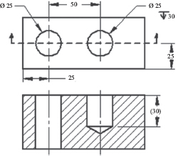
Figure 5.9. Hole dimensions.
5.5.4 DIMENSIONING SLOTS
Slots are common features on shafts and other components. Proper dimensioning of slots depends on their function and form. Length shown may be between centers (Figure 5.10a) or full depending on which is critical (Figure 5.10b). If the end radii are larger than the width of the slot, they should be shown (Figure 5.10c).
5.5.5 DIMENSIONING FILLETS AND ROUNDS
Figure 5.11 shows a fillet and a round. Fillets and rounds are arcs that provide for the smooth transition of faces on an object. They help in removing rough edges, and reduce stress intensification associated with geometric discontinuities in mechanical components. Fillets are used for interior faces and are concave arcs. Rounds are used for exterior faces and are convex arcs. Fillets and rounds should be dimensioned on the view revealing the arc as shown in Figure 5.12. The symbol R for radius must precede the value of the dimension of a fillet or round. When there are several fillets and rounds of the same size on an object, it is common for the size to be specified in a local note such as “All fillets and rounds = 3 mm.”

Figure 5.10. Dimensioning slots. (a) Full length. (b) Length between centers.

Figure 5.11. Fillets and rounds.
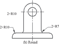
Figure 5.12. Fillets and rounds on a component.
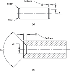
5.5.6 CHAMFER DIMENSIONS
Figure 5.13 shows external and internal chamfers. Chamfers are beveled edges on objects, and they make assembly easier. Chamfers may be specified by notes or dimensions as shown in Figure 5.13a for external chamfer. The setback lengths on the horizontal and vertical directions are used to specify a chamfer by dimensions. The horizontal length is given first (right end of Figure 5.13a). Alternatively, the horizontal setback length and angle may be used for specification (left end of Figure 5.13a). Figure 5.13b shows the dimensioning of an internal chamfer. Notice that three dimensions are needed in the format: the included angle, setback, and small diameter. Half of the included angle could have been used instead. If the specification or note format is used, the setback and half included angle are sufficient for dimensioning.
Figure 5.13. Chamfers. (a) External. (b) Internal.
5.5.7 DIMENSIONING COUNTERBORES, COUNTERSINKS, AND SPOTFACES
Figure 5.14 shows features of a counterbore, countersink, and spotface. Please take time to study the symbols associated with each feature in this figure. A counterbore is a cylindrical recess on a face of an object. It is made by enlarging smaller holes with a boring tool. For the counterbore feature, Φ30 refers to the size of the through hole, Φ40 refers to the size of the step hole, and size 20 refers to the depth of the step hole. A countersink is a conical recess on a face of an object. It is made with a special tool and may be used as seats for screws and centers for cylindrical components like shafts and spindles. For the countersink feature, Φ30 refers to the size of the through hole, Φ37 refers to the size of the tapered hole at the surface of the part, and 82° refer to the included angle of the tapered hole. A spotface is like a counterbore, except that the depth is much smaller. They act as seats for washers and screw heads. For the spotface feature, Φ30 refers to the size of the through hole and Φ60 refers to the size of the step hole. Notice that the depth of the spotface is not specified. This is because a spotface tool is manufactured for specific depth, often not more than 2 mm.
5.5.8 DIMENSIONING KEYSEATS AND KEYWAYS
Keyseats are external slots on shafts, axles, and so on that accept keys. Keyways are internal slots on hubs of cranks, levers, gears, pulleys, sprockets, and so on. Figure 5.15 shows a keyseat and a keyway. Dimensions should be placed such that measurement or inspection of keyseats or keyways can easily be carried out. The length of the keyseat should be shown on the longitudinal view. A broken section is commonly employed for this, as shown in Figure 5.16 where three types of keyseats are indicated. If the keyseat does not start or end at the edge of the shaft, the location dimension must be included as shown in Figure 5.16a and Figure 5.16b.
Figure 5.14. Dimensioning counterbore, countersink, and spotface.

Figure 5.15. Keyseat and keyway.
Figure 5.16. (a) Regular keyseat. (b) Woodruff keyseat. (c) Sledge runner keyseat.
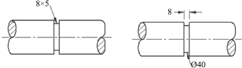
5.5.9 DIMENSIONING NECKS AND UNDERCUTS
Necks and undercuts are used to alleviate the influence of stress concentration and relieve the ends of threads. Necks are common on cylindrical sections, while undercuts are used on faces. There are rectangular, circular, and truncated conical necks or undercuts and are shown in Figures 5.17, 5.18, and 5.19, respectively. The sizes of these features are specified by the width and depth, the width value preceding the depth value as indicated in Figures 5.17a, 5.18a, and 5.19a. Alternatively, the diameter value of the neck section is given as shown in Figures 5.17b, 5.18b, and 5.19b. This is the preferred method for dimensioning necks and undercuts because they can be measured or inspected easily this way.
5.5.10 DIMENSIONING REPEATED FEATURES
Some features like holes are repeated on components. Each feature should not be dimensioned separately; instead, the location and or size for one of the features should be indicated, and then, the total number is included. Figure 5.20a has four holes spaced equally in a linear array. Though there are four holes or circles, the number of equal spacing between the circles is three (3) as indicated. Figure 5.20b has six holes spaced equally on a circle diameter in a radial array. The lower circle in the first quadrant is located by the 30° angle, circle spacing is 6 in number (6 × 60°), not 5, as would be expected in a linear array.
Figure 5.17. Rectangular neck. (a) Depth specified. (b) Diameter specified.

Figure 5.18. Circular neck. (a) Depth specified. (b) Diameter specified.
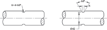
Figure 5.19. Truncated conical neck. (a) Depth specified.
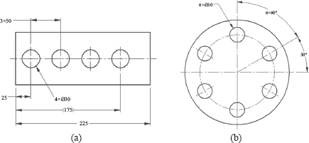
Figure 5.20. Repeated features. (a) Linear array. (b) Polar array
5.6 DIMENSIONING METHODS
Three methods of dimensioning are in common practice. These are datum, chain, and tabular. The datum method is depicted in Figure 5.21 and is preferred for mechanical drawings. A datum may be a point, line, or surface on a component that is assumed to be exact. It is used as a reference for locating other features on the component. A datum point is often chosen at the bottom-left point on a part in view. The chain method is illustrated in Figure 5.22 and is popular in architectural drawings. This method is not recommended for mechanical parts.
Figure 5.21. Datum dimensioning.

Figure 5.22. Chain method.
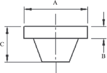
The tabular method is shown in Figure 5.23 and is used in industry to save space and provide information clearly and concisely, saving time and effort. It consists of a diagram dimensioned using letters and a table where values are assigned to the letters. Tabular dimensioning is very common in technical sales catalogs.
Table 5.2. Values of dimensions
Size |
2 |
4 |
6 |
A |
6.5 |
10 |
12.5 |
B |
0.875 |
1.25 |
1.4375 |
C |
2.75 |
3.375 |
3.875 |
Figure 5.23. Tabular method.
5.7 DIMENSION STYLE
When dimensioning in CDD environment, text styles and dimension styles are a great advantage. A text style defines a set of character attributes for specific applications. A dimension style defines a set of attributes for dimension display in specific applications such as mechanical, civil, or architectural. The recommended text height for the dimension value is 3 mm (0.125 in), but space consideration may require a smaller font size. Table 5.3 gives some attributes of the dimension style. Some other attributes are suggested as proportions of the font size or text height.
To set up a dimension style, it is advisable to create a trial dimension so as to judge the suitability of the default text height. The computer screen size of text depends on the size of a drawing, so one dimension text height will not work for every drawing. Sometimes, the dimension text may appear too small or too big with the default font size, and the trial dimension easily reveals this. A trial-and-error approach may be used to adjust the text height to a suitable value. The rule of two or three can be used when adjusting screen text height. Once a suitable dimension text height is arrived at, then the dimension style setup can be completed using the proportions suggested in Table 5.3. The adjustment should be made in the dimension style dialog box, so that the changes can apply to subsequent dimensions.
Table 5.3. Some dimension style attributes (AutoCAD application)
Attribute |
Value |
Dimension unit |
Metric/English |
Dimension text font or style |
Simplex (suggested) |
Text height |
h0 |
Arrow style |
Closed blank |
Arrow size |
≥ h0 |
Extension line cross-over |
h0 |
Extension line offset (gap) |
h0 |
Dimension value location |
Centered |
Dimension value orientation |
Horizontal |
Dimension value location gap |
0.5h0 |
Modern CDD packages are becoming automated in the generation of drawing views and dimension placement as they are progressively being improved. As the capabilities of solid modeling software increase, designers, architects, and engineers will be required to do drafting tasks. Print checking and reading will become dominant skills for technology personnel because they will be required in interpreting and ensuring quality assurance of computer-generated drawings. Therefore, drafting skills will still be relevant in the automated drafting workplace, especially annotation skills.
5.8.1 MANUAL DIMENSION PLACEMENT
Manual dimension placement involves adding dimensional values one at a time by a CDD user. The procedure for dimension placement is virtually the same as would be done in traditional drafting, except that the CDD user has the computer to his or her advantage. In either case, engineering diagrams must be ready before dimensions can be placed. The drawing views should be reviewed and checked for correctness before placing dimensions on them. Correcting plain drawing errors after placing dimensions is tedious and time-wasting even in a CDD environment. In this example, dimensions will be placed manually using a CDD package. The steps for the task of dimension placement are outlined next.
Step 1: Create the plain drawing:
1. Use CDD package routine to generate drawing views.
2. Add hidden lines if necessary.
3. Add centerlines if necessary.
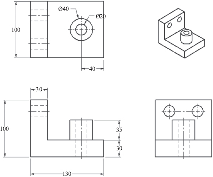
Figure 5.24 is the plain multiview drawing of a component generated from a solid model. The isometric insert is included for completeness and visualization. There is need to provide a good gap between views to make room to the dimensions.
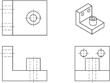
Figure 5.24. Engineering diagram of a component.
Step 2: Set up the dimension style:
1. Create trial dimension.
2. Adjust trial dimension font size if necessary
3. Use dimension style dialog box to complete setup
Step 3: Add horizontal dimensions:
1. Add horizontal sizes on top and front view or top and right view features.
2. Figure 5.25 shows the added horizontal dimensions to Figure 5.24.
Step 4: Add vertical dimensions (front and right view, top view):
1. Add vertical sizes on top and front view or top and right view features.
2. Figure 5.26 shows the added vertical dimensions to Figure 5.25.

Figure 5.25. Adding horizontal dimensions to diagram.
Figure 5.26. Adding vertical dimensions to diagram.
In Figure 5.26, dimensions common to features on adjacent views have been placed between the views. This is the recommended practice. The dimension 50 in the top view may be omitted because it is obvious by visual inspection. However, it is always preferred to explicitly specify dimensions in engineering drawings
Step 5: Add angular dimensions (not applicable in this example). Step 6: Add arc and circle dimensions:
1. Add circle sizes to top and right views.
2. Figure 5.27 shows the circle dimensions to Figure 5.26.
Note that only one of the two circles in the right view of Figure 5.27 is dimensioned with the 2× multiplier added. The 2× is indicative of a repeated feature, twice in this case. Though this example does not present all the features in drafting practice, the principles of dimensioning are the same. When these principles are consistently applied, good annotated drawings will result.
Step 7: Check drawing dimensions:
1. Check all arc and circle features for location dimensions (three holes and a boss).
2. Check all dimensions (verify size and location dimensions).
Step 8: Add notes:
1. Not included in this example.
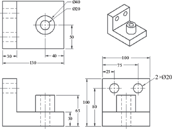
Figure 5.27. Adding circle dimensions to diagram.
1. Print the drawing.
2. Carefully check for correctness and completeness of dimensions.
3. Make corrections as needed.
It may surprise you what you discover in a check print, especially as a new person in the field of drafting. Never turn in a dimensioned drawing without a thorough check on the layout of views and placed dimensions. Errors in dimensional values are hardly tolerated because of associated production cost, rework, and company image.
5.9 CDD AUTOMATIC DIMENSION PLACEMENT
Some solid modeling CDD packages have routines for adding basic dimensions automatically to the plain drawing views that are generated from the solid models. Dimensions from the solid model that can be automatically retrieved are those explicitly defined during the construction of the solid model. Any relevant dimension not defined in the solid construction will have to be manually added later. In some CDD software, angular dimensions are not retrieved from the solid model, so they will have to be manually added. The positions of some of the retrieved dimensions may not be satisfactory. Hence, some form of manual fine-tuning will normally be necessary after automatic centerline and dimension placement routines have been used. In the previous section, the emphasis was on manual skills in basic dimensioning. In this section, advantage will be taken of automatic annotations routines of CDD software. Taking note of the points highlighted previously, the steps for the dimensioning task are outlined. Again, solid edge is used in this example.
Step 1: Generate drawing views:
Let us use the same component of the previous section. Using the view placement routine, generate the drawing views for the component from the solid model as shown in Figure 5.28. Ensure that enough space is provided between views to make room to the dimensions when placing the views.
Step 2: Add centerlines:
As can be observed in Figure 5.28, hidden lines were added to the views when the appropriate routine was used. Centerlines needed to be added. The CDD software used here has a routine for automatic centerline addition to the views. After applying this routine, plain drawing views are obtained as shown in Figure 5.28.
Step 3: Add dimensions:
Using the routine of the CDD software for automatic dimension addition to the views, the dimensions were added to the views of Figure 5.29 with the result of Figure 5.30.
Figure 5.28. Generated views of a component.

Figure 5.29. Add centerlines to generated multiviews.
Figure 5.30. Adding dimensions to multiview drawing.
Step 4: Add missing dimensions and fine-tune dimension positions and placements.
A look at Figure 5.30 will show that:
(a) The positioning of the dimension of the small circle in the top view needs adjustment for clarity.
(b) The positioning of dimension 100 in the front view needs adjustment.
(c) The dimensions 35 and 30 in the front view are chained. This is not recommended for mechanical components; therefore, re-dimensioning is necessary.
(d) The two circles in the right view have no size dimensions. They must be added.
(e) The two circles in the right view have no location dimensions. They must be added.
(f) Figure 5.31 is the fine-tuned dimensioning of Figure 5.30.
A drawing such as that of Figure 5.27 or Figure 5.31 is partially annotated because it lacks tolerances and possibly some vital specifications on material, finishes, heat treatment, and so on. That is, they are not working drawings yet. Working drawings are discussed in Chapter 7.
Figure 5.31. Dimensioned multiview drawing.
5.10 CHAPTER REVIEW QUESTIONS
1. Define design size, actual size, and plot size.
2. What is a dimension?
3. What are the two basic size dimensions?
4. What is a location dimension? How is it different from a size dimension?
5. The U.S. national standard for dimensioning practice is defined in what document?
6. Which view should arcs and circles be dimensioned?
7. State 10 principles of dimensioning mentioned in this chapter.
8. Why do you think clarity is important during dimensioning?
9. Should dimensions always be placed outside a drawing view?
10. Should you avoid overlapping of dimension and extension lines?
11. What are the styles used in dimensioning slots?
12. What are the styles used in dimensioning undercuts?
13. What are chain and baseline dimensioning?
14. Which method is not recommended for mechanical drawings?
5.11 CHAPTER EXERCISES
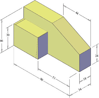
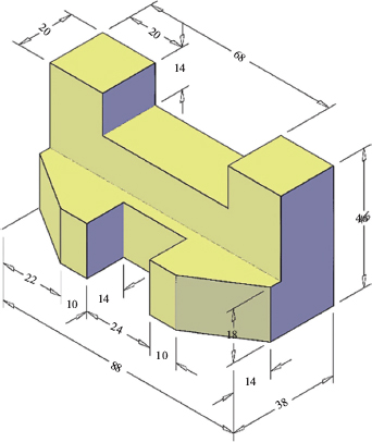
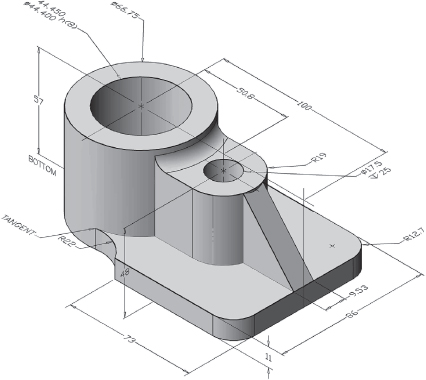
Create the top, front, and right views of the following figures and add dimensions.
Figure P5.1. Problem 1.
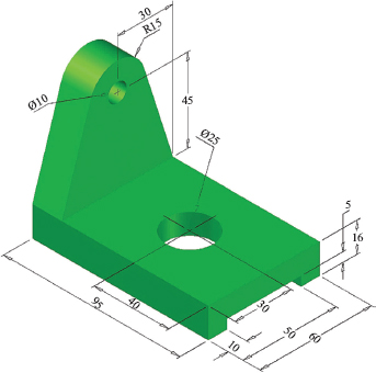
Figure P5.2. Problem 2.
Figure P5.3. Problem 3.

Figure P5.4. Problem 4.
Figure P5.5. Problem 5.

Figure P5.6. Problem 6.
Figure P5.7. Problem 7.