6.1 INTRODUCTION
Isometric drawings are a type of pictorial drawings that show the three principal dimensions of an object in a single view. The principal dimensions are the overall sizes for the object along the three principal directions. Pictorial drawings consist of visible object faces and the features lying on the faces. The internal features of the object are largely hidden from view. Pictorial drawings tend to present images of objects in a form that mimics what the human eye would see naturally. Nontechnical personnel can interpret them because they are generally easy to understand. Pictorial drawings are an excellent starting point in visualization and design and are often used to supplement multiview drawings. Hidden lines are usually omitted in pictorial drawings, except where they aid clarity.
An isometric drawing is one of the three types of axonometric drawings. It is created on the basis of parallel projection technique. The other two types of axonometric drawings are dimetric and trimetric drawings. In isometric drawings, the three principal axes make equal angles with the image plane. In a dimetric drawing, two of the three principal axes make equal angles with the image plane, while in a trimetric drawing; the three principal axes make different angles with the image plane. Isometric drawings are the most popular and are easier to construct than the others. Some computer design drafting (CDD) packages can generates all three types of views.
6.2 ISOMETRIC PROJECTION AND SCALE
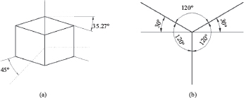
An isometric projection is a representation of a view of an object at 35°16’ (35.27°) elevation and 45° azimuth. The principal axes of projection are obtained by rotating a cube through 45° about a vertical axis, then tilting it downward at 35°16’ as shown in Figure 6.1a. A downward tilt of the cube shows the top face, while an upward tilt shows the bottom face. The 45° rotation is measured on a horizontal plane, while the 35°16’ angle is measured on a vertical plane. The combined rotations make the top diagonal of the cube to appear as a point in the front view. The nearest edge of the cube to the viewer appears vertical in the isometric view. The two receding axes project from the vertical at 120° on the left and right sides of the vertical line, as shown in Figure 6.1b. These three axes form the principal axes and are parallel to the cube edges in the isometric view. The two receding axes are inclined at 30° to the horizontal line, while the vertical axis is at 90° to the horizontal line. The three visible faces of the cube are on three planes called isoplanes and are referred to as left, right, and top isoplanes. The front view of objects is commonly associated with the left isoplane, the right view with the right isoplane, and the top view with the top isoplane. Lines on an object parallel to the isometric axes are referred to as isometric lines, while lines not parallel to them are known as nonisometric lines, as shown in Figure 6.2a. Isometric projection is not the most pleasant to the human eye, but it is easy to draw and dimension.
Figure 6.1. Isometric projection. (a) Isometric rotations. (b) Isometric axes in image plane.
In pictorial projection, the regular axis is usually inclined at 45°, but the receding axes in an isometric projection are inclined at 30° to the horizontal. Hence, there is a difference in orientation between the receding isometric axis and the regular axis. These orientations of axes are shown in Figure 6.2b, where a measurement of 10 units along the regular axis projects to 8.16 units on the isometric axis. Thus, one unit of measurement on the regular axis is equal to 0.816 on the isometric scale. This means that a regular length of one unit must be scaled to 0.816 units in an isometric projection.
Now, isometric projection is an accurate representation of an object on the isometric scale, that is, when measurement is made along the isometric axes. This is about 18 percent short of the actual dimensions of the object. In practice, a regular length of one unit is drawn as one unit on the isometric axis, thus introducing some error to the projection. Hence, the actual images of object shown in isometric views are called isometric drawings, and not isometric projections. The main difference between an isometric projection and an isometric drawing is size. The drawing is slightly larger than the projection because it is full scale. Features in isometric drawings may be created on isometric planes or nonisometric planes. For features on nonisometric planes, it will be helpful to first create them on isometric planes and then project them to nonisometric planes during construction of isometric drawings. Please refer to Figures 6.10 to 6.13.
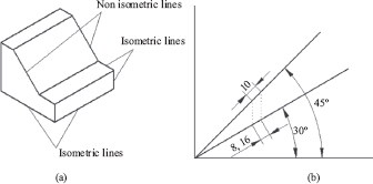
Figure 6.2. (a) Types of isometric lines. (b) Isometric scale.
6.3 TYPES OF ISOMETRIC DRAWINGS
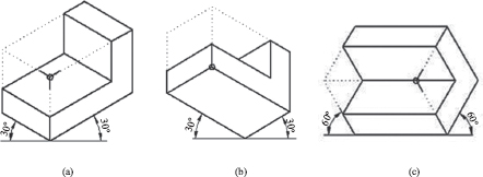
Isometric axes can be positioned in different ways to obtain different isometric views of an object. Three basic views are in general use, and they are regular isometric, reverse isometric, and long-axis isometric, as shown in Figure 6.3. In regular isometric, the viewer looks down on the object, so the top of the object is revealed. The receding axes are drawn upward to the left and right at 30° from the horizontal. The nearest end of the object is at the lower front base of the bounding box (B-box), as shown in Figure 6.3a. This is the most common type of isometric drawing. The viewer in reverse isometric is looking-up at the bottom of the object, so this view reveals the bottom of the object. The receding axes are drawn downward from the horizontal at 30° with the lower back end at the base of the B-box, see Figure 6.3b. The long-axis isometric keeps the largest principal dimension of the object horizontal as one principal axis. This is normally used for objects with length considerably larger than the width or depth. The viewpoint could be from the left or right side of the object, but the long axis is drawn horizontal and the others are drawn at 60°, as indicated in Figure 6.3c. The long-axis isometric is the least used.
Figure 6.3. Types of isometric drawings. (a) Regular. (b) Reverse. (c) Long-axis.
6.4 CONSTRUCTING ISOMETRIC ARCS AND CIRCLES
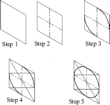
Arcs and circles are common features on objects, especially in mechanical design drafting. Isometric arcs are portions of isometric circles that are ellipses on isometric planes. Figure 6.4 shows a component with isometric arcs on the right face or right isoplane. As the arcs are portions of isometric circles, the technique for creating isocircles will be discussed. It is worth noting that an isometric arc can be constructed without creating a full isometric circle. One important rule to remember when creating curves in isometric projection is that the isometric face on which the curves lie on should be created first using guide or construction lines. Then, the curves can be created using projection of key points and intersection of projection lines from the key points. A second rule is that true dimensions are transferred to nonisoplanes. Hence, where there are inclined and oblique faces, the true sizes of features on the auxiliary views should be used during construction. There are several techniques available for creating isocircles, but an easy and more popular one is the four-center ellipse. The four-center ellipse is an approximate ellipse, but it is usually good enough for most drafting applications. Figure 6.5 shows in five steps, the creation of the top isocircle.
Step 1: Draw a square using the circle diameter as size:
For the top isocircle, the top isoplane is the right surface to draw the square. The top isoplane is horizontal as can be seen in Step 1 of Figure 6.5. Draw the isometric square.
Step 2: Draw the centerlines of the square:
Draw the two centerlines of the square as shown in Step 2 of Figure 6.5.
Step 3: Draw the big arcs of the isocircle:
Identify the key points K1 and K2. These are two centers of the four-center ellipse technique. Notice that these centers are located at the obtuse angle corners of the isometric square. Using the radius R, with centers at K1 and K2, draw the two big arcs for the isocircle as shown in Step 3 of Figure 6.5.
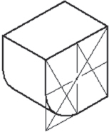
Figure 6.4. Isometric arcs.
Step 4: Locate the centers of the small arcs of the isocircle:
Draw the diagonal K3-K4 between the acute angle corners of the square in Figure 6.5. Then, draw lines K1-K5 and K2-K6. The intersection (K7) of the lines K3-K4 and K1-K5 in Step 5 locates one center for a small arc. The other small arc center is located at K8, the intersection of lines K3-K4 and K2-K6.
Step 5: Draw the small arcs of the isocircle:
Using the centers of the small arcs K7 and K8, draw the two small arcs of radius r, as shown in Step 5 of Figure 6.5. Verify that the big and small arcs are tangent to the isometric square. If a CAD package is used, circles could be drawn instead of arcs. The circles must then be trimmed to obtain the arcs required in the isocircle. Figure 6.6 and Figure 6.7 show, respectively, in five steps, how the left and right isocircles can be created. These steps are the same as described earlier in Figure 6.5 for the top isocircle, except that the isoplanes are, respectively, the left and right ones.
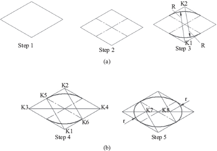
Figure 6.5. (a) Constructing top isocircle. (b) Constructing top isocircles continued.
Figure 6.6. Constructing a left isocircle.
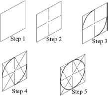
Figure 6.7. Constructing a right isocircle.
The construction of isometric arcs follows the same steps as isocircles as described. However, a quick visual inspection of the arc in a problem will reveal which quadrant(s) the arc is located in. Quarter arcs and half circle arcs are quite common in mechanical drafting. For example, Figure 9.4 has a quarter arc on one of the acute angle corners, requiring the construction of one of the small radius arcs in an isocircle.
The five steps described previously for creating isocircles could be reduced to three, as shown in Figure 6.8 by combining Steps 1 and 2 as Step 1; and combining Steps 3 (without drawing the large arcs) and 5 as Step 3. This leaves Step 4 as the new Step 2 in which all the key points K1 to K8 are created. The centers of the four arcs can then be identified as K1, K2, K7, and K8. In the last step (new Step 3), the four arcs are created, as shown in Figure 6.8.
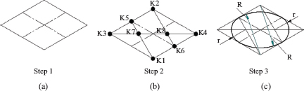
Figure 6.8. Constructing top isocircle.
6.5 CONSTRUCTION TECHNIQUES FOR ISOMETRIC DRAWING
It is quite easy creating isometric lines on isometric planes. This is done by drawing the lines parallel to isometric axes. However, creating non-isometric lines and angles must be done with care. In general, angles of nonisometric lines are drawn by creating line segments between the end points of the locations that form the angle. Irregular curves are created from intersections of projection lines from isometric planes. The two common techniques generally used for isometric drawings are the box and the centerline layout techniques.
6.5.1 BOX TECHNIQUE FOR ISOMETRIC DRAWINGS
The box technique is the most common construction technique and is also known as the coordinate technique. In the approach, a bounding (B-box) is first made with guide lines using the principal dimensions on the object. The principal dimensions may be designated as W for width, H for height, and D for depth. It may be necessary to add-up dimensions along the principal axes to get the principal dimensions of an object. The faces on the objects are then created after the B-box is ready. Each feature on the object is properly located and created within the B-box. This technique is good for drawing objects with angular and radial features or objects that have irregular shapes or form. The general steps in the box technique are:
1. Define the origin of and create the isometric axes.
2. Create the bounding box using the principal dimensions.
3. a. Use dimensions from top and front view to mark out faces.
b. Or, use dimensions from top and side views to mark out faces.
4. Locate and create all features on the faces.
5. Finish and check the drawing.
6.5.2 OBJECT WITH NORMAL FACES
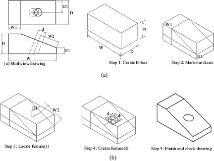
Figure 6.9 shows the construction of the isometric drawing of an object with normal faces. The multiview drawing of the object is shown in Figure 6.9a. Note that Step 4 in the general procedure is not needed for this object.
Steps 1 and 2 of the general procedure can be combined into one by drawing the B-box directly, keeping the isometric axes direction in mind.
6.5.3 OBJECT WITH INCLINED FACES
Figure 6.10 shows the construction of the isometric drawing of an object with inclined face. The multiview drawing of the object is shown in Figure 6.10a. Note that Step 4 in the general procedure requires the creation of an isometric circle on the inclined face.
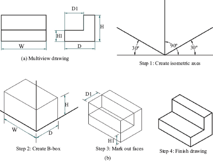
Figure 6.9. (a) Box method for normal faces. (b) Box method for normal faces continued.
Figure 6.10. (a) Box method for inclined face. (b) Box method for inclined face continued.
6.5.4 OBJECT WITH OBLIQUE FACES
Figure 6.11 shows the construction of the isometric drawing of an object with oblique face. The multiview drawing of the object is shown in Figure 6.11a. Step 4 in the general procedure is not required in this object.
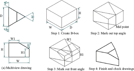
6.5.5 OBJECT WITH ANGLED FACES
Figure 6.12 shows the construction of the isometric drawing of an object with angled faces. The multiview drawing of the object is shown in Figure 6.12a. By inspection of the multiview drawing, it is clear that the right vertex on the top view is at the midpoint of the depth dimension D. This helps in locating the vertex on the B-box without using trigonometry. Observe that, with the front angle of 30° and the dimensions W and W1 given, the dimension H1 would not be shown. So, H1 must then be calculated using trigonometry. It can be shown that: H1 = H − (W − W1) × tan30°. Thus, the lines defining the angles on the object can be created on the B-box without actually measuring the angles 60° and 30°. Always remember that angles on an object are not directly measured in isometric construction. They are used to calculate the end points of lines defining the angles. Finally, note that Step 4 in the general procedure is not required in this object.
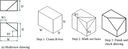
Figure 6.11. Box method for oblique face.
Figure 6.12. Box method for angles.
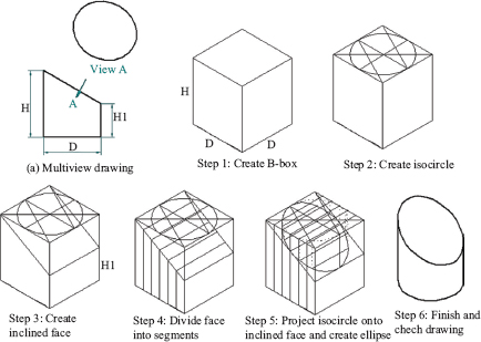
6.5.6 OBJECT WITH ELLIPSE ON INCLINED FACES
Figure 6.13 shows the construction of the isometric drawing of an object with angled faces. The multiview drawing of the object is shown in Figure 6.13a. Step 1 follows the general procedure and Step 2 creates the isocircle for the cylinder. In Step 4, the inclined face is divided into segments that are used to project the isocircle onto the inclined face in Step 5. These two steps are perhaps the most challenging in this problem. Care is needed to first transfer the segments to the isocircle so as to define the key points on the isocircle that will be projected onto the inclined face. Then, the key points so established are transferred to the inclined face and the ellipse is created. Again, note that Step 4 in the general procedure is not required in this object.
Figure 6.13. Box method for ellipse on inclined face.
6.5.7 OBJECT WITH IRREGULAR CURVES
Figure 6.14 shows the construction of the isometric drawing of an object with an irregular curve. The multiview drawing of the object is shown in Figure 6.14a. Step 1 follows the general procedure. In Step 2, the dimensions shown on the top view of Figure 6.14a are used to mark out the key points on the curve. It is like dividing the curve into segments so that enough key points can be generated and used to approximate the curve. Step 3 shows the creation of the irregular curve. Again, note that Step 4 in the general procedure is not required in this object.
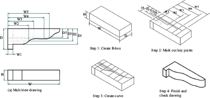
Figure 6.14. Box method for irregular curve.
6.5.8 C ENTERLINE TECHNIQUE FOR ISOMETRIC DRAWINGS
The centerline technique is better for objects with many circular and arc features. This method begins with a construction of all the centerlines in the object using the top or bottom face as reference. Other features are added to complete the drawing. Figure 6.15 shows the use of the centerline method in the construction of an object. In it, the following steps are outlined:
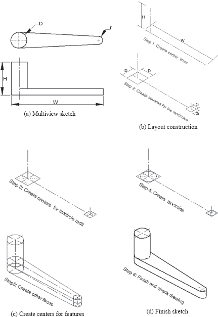
Figure 6.15. Centerline method for isometric drawing.
Step 1: Create the centerlines:
All centerlines in the object are created and aligned with isometric axes. The size of the object will determine the length of the centerlines. Either the top or bottom face of the object can be used as reference. The bottom face was used as reference in Figure 6.15.
Step 2: Create isocircle squares:
On the centerlines drawn in Step 1, locate the centers of the isocircles. Using the dimensions available, draw the squares for the isocircles on one face as shown in Step 2 of Figure 6.15.
Step 3: Create arc centers for isocircle on one face:
Using the four-center ellipse technique, create the centers of the arcs for the isocircles on one face.
Step 4: Create isocircles on one face:
Once the centers of the arcs for the isocircles are finalized in Step 3, create the arcs for each isocircle.
Step 5: Create isocircles on the other faces:
Repeat Steps 2 to 4 for other faces.
Step 6: Finish and check the drawing
Complete the drawing by creating connecting features to the isocircles and removing lines and arcs that are hidden. Check that the drawing is correct.
6.6 ISOMETRIC ANNOTATIONS
Isometric annotations consist of textual information added to isometric views for complete documentation. These include dimensions, notes, tables, and so on. Annotations should be placed on isoplanes, and dimension lines should be parallel to isometric axes. As much as is possible, keep all dimensions outside of view and show dimensions between points on the same plane only. Arrowhead heel should be parallel to the extension lines, and the dimension value should show clearly. The front (for width dimensions) and right (for depth dimensions) isoplanes are preferred for annotations. Figure 6.16a shows a box dimension with the preferred format; however, Figure 6.16b shows the same box dimension with the width and depth sizes on the top isoplane. This is also a common format for isometric dimensioning. The height dimensions are placed vertical and could be on the front or right isoplane. The dimension value can be placed aligned with the dimension line or placed horizontally. Though the aligned placement is recommended by ANSI/ASME, the horizontal placement is common, perhaps due to relative ease when drawing manually or sketching freehand.
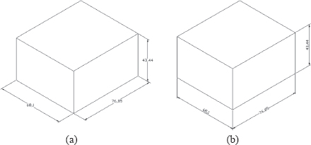
Figure 6.16. Isometric annotations. (a) Aligned dimension placement. (b) Horizontal dimension placement.
6.7 APPLICATIONS OF ISOMETRIC VIEWS
Isometric views are used in component and assembly drawings. Isometric component pictorials may be presented in two formats: isometric detail drawing or isometric insert view. Isometric detail drawing is a single view with proper annotations. Isometric insert view is an isometric view of a component that is added to necessary orthographic views principally to aid visualization and sometimes for completeness of documentation. In assembly drawings, isometric views provide a general graphic description of each component in outline, exploded, and section views. Section pictorial views show all internal components in mating position at a plane defined by the cutting plane line. Broken section isometric views are used in assembly and detail drawings.
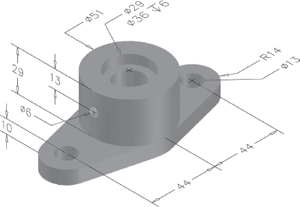
6.7.1 ISO-DETAIL DRAWINGS
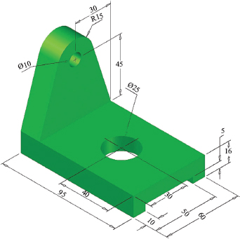
Annotated isometric view of a component may be referred to as iso-detail drawing. This is a single isometric view drawing of a component with all specifications and dimensional information necessary for the manufacture and inspection of the component. This is done mostly for components with relatively simple form. Figure 6.17 shows two examples of iso-detail drawings. However, sketched isometric views may be dimensioned during design development. Because these sketches are not drawn to scale, they are not iso-detail drawings, but may be called iso-detail diagrams. In orthographic detail drawings, it is common in practice to have an isometric view included, though annotations are not added to the isometric view.
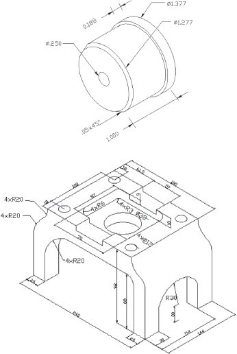
Figure 6.17. Iso-detail drawings.
6.7.2 ISOMETRIC SECTION AND EXPLODED VIEWS
Different types of sections in isometric views can be created, but the common ones are the straight (full), half, broken, and offset sections. Objects of irregular interiors are good candidates for isometric sections. Hatch line inclination should be chosen with care to ensure that they are not parallel to isometric lines or feature lines. A 60° inclination for hatch patterns is a common practice. Other angles should be used where this is not appropriate. Figure 6.18a and Figure 6.18b show examples of isometric full section and half section, respectively. Figure 6.18c and Figure 6.18d show examples of isometric broken and offset sections, respectively.
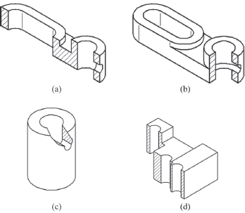
Figure 6.18. Isometric section views. (a) Straight section. (b) Half section. (c) Broken section. (d) Offset section.
6.7.3 ISOMETRIC ASSEMBLY VIEWS
Two types of isometric assembly views are in common use, and they are the outline and exploded isometric views. Outline pictorial views show all external components in mating positions as the example in Figure 6.19a. Exploded pictorial views show all components in relative position at some distance apart, but aligned to adjacent components. Exploded assembly drawings are great aids in assembling, installations, and maintenance of products. They are popular in catalogs, maintenance manuals and guides, technical illustrations, and so on. They are normally arranged along isometric axes with cases of several offsets if assembly is of a complex product. Figure 6.19b shows the exploded isometric view of Figure 6.19a.
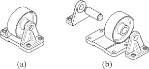
Figure 6.19. Assembly isometric views. (a) Outline. (b) Exploded.
6.8 DIMETRIC AND TRIMETRIC PROJECTIONS
Dimetric and trimetric projections are similar to isometric projection, but differ in the angles between the reference axes on the image plane. Figure 6.20 shows examples of isoplanes on cubes for dimetric and trimetric projections. In diametric projection, two of the angles between the principal axes are equal as shown in Figure 6.20a. These angles are normally greater than 90°, but less than 180°. The angle 120° produces an isometric projection, so it is not acceptable in dimetric projection. The third angle is chosen to be less or greater than the value of the equal angles. Common values for angles in dimetric projection are 15°, 20°, 25°, 35°, and 40°, with the horizontal line at the base of the cube. It is much easier constructing isometric drawing than dimetric drawings. In trimetric projection, the angles between the principal axes are different from each other as indicated for the example in Figure 6.20b. Though this gives greater flexibility in the drawings that may be created, the construction process is more tedious than even that for diametric drawings. Thus, it is rare to find trimetric drawings. Some CAD packages allow dimetric and trimetric views to be generated from solid models. However, isometric drawings are the favorites.
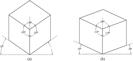
Figure 6.20. Examples of isoplanes in other axonometric projections. (a) Dimetric. (b) Trimetric.
1. What is an isometric projection?
2. What is the difference between an isometric projection and an isometric drawing?
3. Specify the rotation angles in the horizontal and vertical planes for isometric projection.
4. List the types of isometric drawings you know.
5. Define isometric and nonisometric lines.
6. What are isometric circles?
7. Name the technique used in creating isometric circles in this chapter.
8. Name the two techniques used in this chapter to create isometric drawing.
9. When would you prefer the centerline technique appropriate for isometric drawings?
10. What is an iso-detail drawing?
11. List the types of isometric assembly drawings commonly found.
6.10 CHAPTER EXERCISES
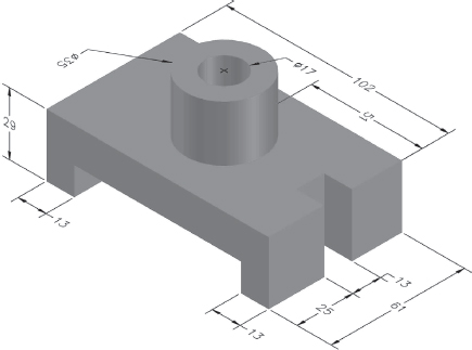
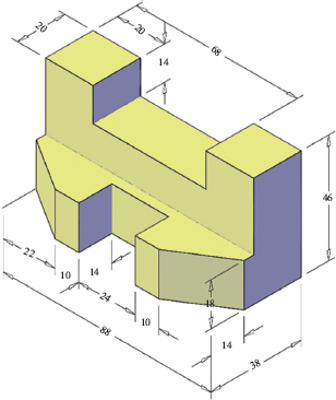
Sketch the isometric views shown in the following figures. The last two figures are in inch dimensions.
Figure P6.1. Problem 1.
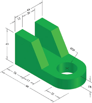
Figure P6.2. Problem 2.
Figure P6.3. Problem 3.
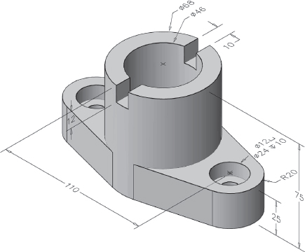
Figure P6.4. Problem 4.
Figure P6.5. Problem 5.