The various categories of gear described here all served a single purpose: keeping airmen alive and well in a hostile environment, whether in the air, on the ground, or in the ‘drink’. Considerable effort and resources were expended in the attempt. Besides issuing the best possible clothing and equipment, coupled with extensive initial training in their use, the combat replacement centres provided all airmen newly assigned to a theatre with two weeks of area-oriented instruction on flying clothes, parachutes, flak suits, oxygen equipment, first aid, and ditching proced ures. Proper care and use of the many and varied flyers’ equipments was so critical that non-rated (non-pilots) Personal Equipment Officers (PEO) and enlisted Personal Equipment Technicians (PET) were authorised in flying units in March 1943. PEOs worked closely with unit medical, safety, and oxygen officers to provide instruction in the proper installation, care, and function of protective clothing and emergency equipment.
Two popular and widely used flying caps. (Top): The light OD gabardine B-1 summer cap. (Bottom): The seal brown shearling B-2 winter cap with the ear flaps down; they could be folded up exposing the fleece lining.
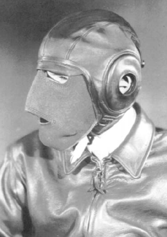
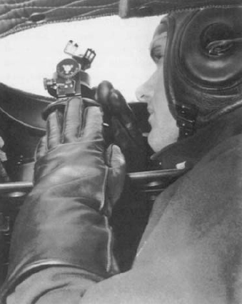
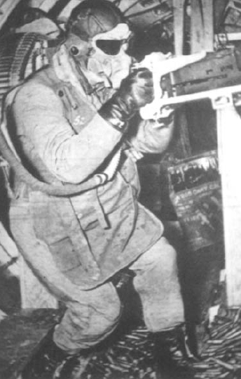
The D-1 face mask, which could not be used with an oxygen mask, is worn with the A-11 intermediate helmet and A-2 jacket. This type of rubber earphone retaining cups were used in the later AN-H-15 and -16 helmets and added to B-6 winter helmets.
Besides issue equipment, it was not uncommon for units to develop their own protective and survival gear. (An example of unit-developed gear was a backpack jungle survival kit with an attached one-man raft used by XIII Fighter Command.) While unit-developed items often served a unique need or made up for shortages, difficulties were occasionally encountered due to insufficient testing or unsuitable materials.
Equipment will sometimes be found with a conspicuous one to three digit number stencilled on it. These were usually items that were stored outside an individual airman’s locker, e.g. kit bag, oxygen mask, life vest, electric heated suit. In some units certain equipment items, e.g. flak jackets or electric suits, were pooled for use by several individuals if sufficient quantities were not available. These too were marked with numbers.
The equipment described here was used by individual airmen, we do not address equipments intended for groups of personnel such as multiplace life rafts and crew survival kits.
AAF (and later US Air Force) parachutes were designated by type letters identifying the position in which they were worn. A—chest, B—back, S—seat, T—training or troop. The latter, used by paratroopers, were composed of a main backpack and a chest-mounted reserve. Though this system was retained, some parachutes were redesignated, with slight modification, under the 1942 Army-Navy standardisation programme. Since the differences between the original AAF models and the AN versions were so slight, they will be discussed here together. There were also many minor manufacturing modifications to parachute pack assemblies, harnesses, and canopies, far too numerous to discuss here. There were even differences between the AN standardised parachutes with minor construction refinements preferred by both services. Army versions’ AN drawing numbers were followed by ‘-1’ while the Navy’s had ‘-2’.
The development and testing of parachutes had been conducted by the Engineering (later Material) Division’s Parachute Branch at McCook Field, Ohio, since 1919. The use of parachutes by aviators was made compulsory in 1921. In 1927 the Material Division was moved to the nearby, new Wright Field and parachute development was continued under the Experimental Engineering Section.
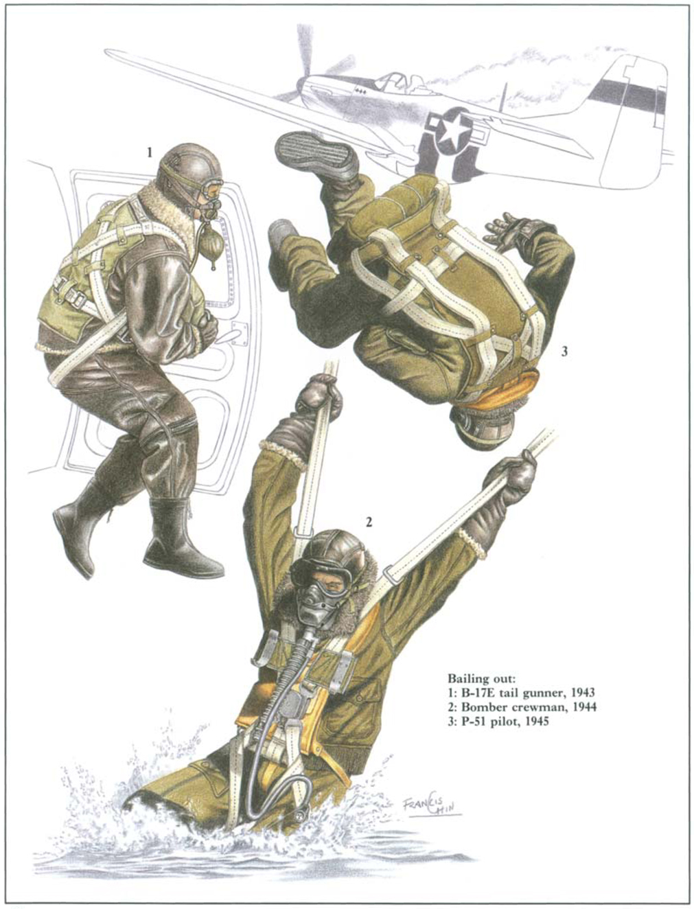
The use of the different types of parachutes depended on the flyers’ crew position or type of aircraft. Most large aircraft, bombers and transports, permitted the use of the flexible back type parachutes, which conform to the wearer’s back contour. Though intended to be worn at all times while airborne, they were sometimes stowed near the crewman’s station or exit during non-combat sorties for comfort or ease of movement. Bomber crewmen operating in confined positions or requiring additional mobility used quick attachable chest (QAC) parachutes: rather than removing the entire parachute assembly, QAC parachutes permitted airmen to wear the harness and remove only the parachute pack, which could be quickly snapped on if needed. They were stowed near their emergency exit together with a one-man life-raft. Ball turret, tail, and waist gunners used these extensively. Fighter pilots preferred seat parachutes (which allowed the head to be turned more freely), though in the Pacific, most used back types since seat parachutes were uncomfortable on long flights.
B-17 waist gunner wearing the A-9 winter gloves and an AN-H-16 winter helmet. Two AN6020-1 walk-around bottles can be seen under the gun’s feed chute.
Parachute pack assemblies were made of 12.29 oz. per sq.yd. cotton duck, either light OD or the later dark OD. The pack contained and protected the canopy; it had internal loops in which the suspension lines were stowed and elastic pack opening cords, and included the ripcord fittings. Pack opening cords were made of  in. diameter elastic, white or dark OD with black threads.
The harness served to fasten the pack to the airman, acted as a ‘seat’ for the ride down, and permitted the attachment of survival gear. Harnesses were originally made of natural (white) linen Type VII webbing with a breaking strength of 2,800 lbs. and a life of two years. White cotton webbing with a similar breaking strength, and much longer service life, replaced linen before the war. This in turn was replaced by white cotton webbing with nylon filling (reinforced), first procured in early 1942, principally to reduce swelling in harness hardware; this had a breaking strength of 2,900 lbs. Late in the war dark OD and brown webbing were used. All of these webbing types were 1¾ in. wide; cotton and cotton/nylon webbing had a black identifying yarn woven into the centre.
Harnesses were fitted with a back pad cushion, the design depending on the type of parachute. Pads were OD canvas covered and filled with bound hair or foam rubber. These could be replaced with emergency parachute back pad containers containing survival gear (see Emergency Kits).
Until 1944 emergency parachute harnesses were of the adjustable three-point connection type; a single chest strap and two leg straps that connected to the main harness assembly. The British-developed single-point, quick release box (QRB), called the ‘Irvin type box’ after the manufacturer, was first tested by the US in the mid-1930s; a fatal test jump in 1941 precluded its planned adoption. It was composed of an assembly allowing the chest and leg straps to be snapped into a single fitting on the wearer’s chest. By rotating, to unlock, and then slapping the circular release plate, all straps were released, permitting rapid removal of the harness. Development by the British was influenced by their extensive overwater flight requirements, as it allowed rapid removal in the water; this was not then considered a major concern by the US. In early 1943 VIII Bomber Command was using 2,500 British parachutes with the QRB, and requested the device be incorporated into US models; this was again rejected because of perceived safety, manufacturing, and maintenance difficulties. However, in late 1943 a safety fork, copied from the German version of the QRB, was adopted and orders were placed in March 1944 for redesigned harnesses incorporating the release, though there were still some flaws in the design.
Hardware fittings were made of aircraft quality drop forged alloy steel. Spring-loaded snap hooks were coupled to ‘V’ rings for the chest and leg strap connections, both with a 2,500 lb. tensile strength. The larger snap hooks on early chest packs were coupled to ‘D’ rings attached to the harness, both with a 5,000 lb. tensile strength. From 1943 QAC type harnesses (A3 parachute and later types) had the ‘D’ rings on the pack’s back and snap hooks on the risers. Some earlier model parachutes still in use had bayonet type harness fasteners—a male-female, twist and lock fitting with a 2,000 lb. tensile strength. Rectangular adjusting strap adapters, fitted at the harness shoulders, had a 1,000 lbs. tensile strength. Connector links, linking the suspension lines to the harnesses’ riser straps, had either a 1,500 or 3,000 lb. tensile strength. Parachute suspension lines were permanently fastened to the harness risers (no canopy releases were used as on today’s parachutes, to allow the jumper to jettison the canopy in water or when being dragged by high ground winds). Back and seat parachute ripcord housings were made of flexible, coiled stainless steel tubing.
Prior to the war all parachute canopies and suspension lines were fabricated of japanese silk, 1.75 oz. per sq.yd. In anticipation that a conflict with Japan would cut off supplies from the Far East, the Air Corps began experiments with substitute materials as early as 1927. These initially included cotton (too bulky, lacked sufficient tensile strength, slow opening) and domestic silk. Domestic output was limited and more costly; but it was standardised for emergency war production in 1930. Silk canopies had a service life of five years, unless used in the tropics which reduced it to two years. Rayon was tested in 1929–30 and was also standardised for emergency war production if sufficient silk was not available, but lacked silk’s strength and elasticity. Nylon was tested in 1939 and compared favourably with silk, being stronger, but slightly bulkier. The first nylon canopies and suspension lines were procured in late 1941. Improvements in the synthetic were made and additional nylon canopies were ordered in early 1942; the last silk canopies were made in the spring of 1943. Nylon 16 oz. per sq.yd. twill also has the benefit of not deteriorating as rapidly with age (service life was seven years), though it is damaged by prolonged exposure to sunlight. Nylon also absorbs little water, dries quickly, and is not damaged by salt water. The extensive demand on America’s fledgling nylon industry did have the drawback of requiring the same amount of nylon as 500 pairs of ladies’ stockings for one parachute. The hundreds of thousands of parachutes required explains the severe wartime shortage of that commodity, so often commented on in motion pictures.
The basic emergency parachute canopy was the 24 ft. diameter flat circular design; its 452 sq.ft. of nylon was constructed of 24 gores (pie-slice shaped segments) of four panels each. Twelve continuous, nylon 375 lb. test suspension lines (silk lines were 450 lb.) were sewn into the gore seams providing 24 lines attached to the harness riser straps. Limited use was made of an identically designed 28 ft. diameter, 616 sq.ft. 28 gore and line canopy with some seat type parachutes (for use by men over 180 lbs.). Canopies were solid white, and although OD and camouflage canopies were considered, they were not adopted. Attached to the apex of all emergency canopies was a white 28, 30, or 36 in. spring-loaded ‘spider’ pilot parachute to aid extraction from the pack. Standard 24 ft. canopies were identified by drawing number 42G2001-series while the 28 ft. were the 42J2019-series. Parachute assemblies weighed 18–22 lb., the QAC and seat types being slightly lighter than back types.
Quick attachable chest type parachutes were designated either as Group 1 red or Group 2 yellow, the two groups’ packs and harnesses not being interchangeable. The harnesses and chest packs’ ripcord protector flaps were marked with the appropriate colour to ensure a correct match. The A-2 parachute (from 1942, AN6513–1 and -1A) was a QAC model standardised on 6 November 1936 and the only type designated in Group 1 red. The two-pin, short cable ripcord handle was on the wearer’s right end of the rectangular pack. When the canopy inflated, the risers suspended the jumper by the chest causing a head-back attitude and resultant landing difficulties. Its harness had ‘D’ rings mounted on the vertical chest straps to which the pack was attached by snap hooks. Some British chest parachutes incorporating the single-point QRB were used by the Eighth AF and proved to be very popular. With an increased need for QAC parachutes in 1942, and the desire for the jumper to be suspended by the shoulders as with other parachutes, the A-3 parachute was developed. This, and all subsequent types (Group 2 yellow), had the ‘D’ rings on the pack’s back and snap hooks on the risers, which were clipped to the shoulder straps. When opened, the container was pulled up above the jumper with the risers, though jumpers were sometimes smacked in the face by the pack. It offered shoulder suspension, but still featured a three-point connection rather than the desired single-point QRB, and was little used. The A-4 parachute, standardised on 14 December 1944, incorporated the QRB. A design flaw prevented its release (desirable when landing in water) while bearing the jumper’s weight, was uncomfortable, and the riser snap hooks sometimes caused head injuries during opening. The A-5 parachute, incorporating the desired QRB and harness improvements, was standardised on 5 January 1945.
A C-54 pilot wearing A-12 arctic gloves (actually one-finger mittens) made of light OD gabardine with brown leather palms and lined with fleece. He also wears an A-11 intermediate helmet and B-15 intermediate jacket.
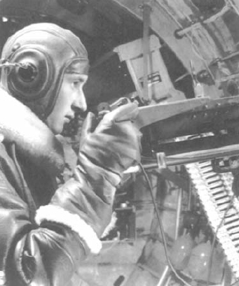
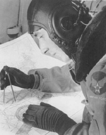
A navigator, operating an AN5738-1 astro compass, wears the F-2 electric heated gloves with an AN-H-16 winter helmet, and the F-2 electric suit’s outer jacket.
The B-4 and B-5 parachutes were standardised on 31 August 1939 and 15 March 1940 respectively. Both were improvements over earlier models, but were outclassed by the B-7. Both were made limited standard in 1940, saw little use in the war and were declared obsolete in 1942 and 1944 respectively. The B-7 parachute (from 1942, AN6512–1 and –1A) was a back type standardised on 1 October 1940. It used a three-pin ripcord (all back types had the handles on the left side of the harness) and a buckled waist band integral to the pack and in addition to the three-point connection (deleted on the later AN6512–1); many had old bayonet-type harness fasteners. Its harness and pack were uncomfortable and it was replaced by the B-8 parachute standardised in late 1942. B-7s continued to be used though. The B-8 had a more comfortable harness and soft pack, moulding to the contour of the wearer’s back, deleted the waist band, and used a four-pin ripcord. Some early harnesses used bayonet fasteners, but most had snap hooks. A small number were modified with a larger container to accommodate the 28 ft. canopy. The B-9 parachute was standardised on 1 January 1944, using the B-8s soft pack, but with a single-point QRB harness connection, which caused the same release difficulties as the A-4; improper fitting could also cause groin injuries, and the riser adapters sometimes inflicted head injuries during opening. The B-10 parachute was standardised on 5 January 1945 using the B-8 container, an improved QRB and harness, and was the first parachute to feature a ripstop nylon canopy.
While all QAC and back type parachutes in use at the beginning of the war were recent designs, the then current seat models were of much earlier origin. All seat types had a 2 in. thick seat cushion made of OD duck-covered sponge rubber. In 1943 these were replaced by bound hair-filled cushions due to the rubber shortage that year. Even though the rubber cushions had replaced a pneumatic model in early 1939, this model was sought by pilots in the Pacific flying long-range missions, due to its comfort. Special seat pads for survival gear were also used (see Emergency Kits). All seat types were fitted with a two-pin, long cable ripcord with the handle on the left side of the harness.
The S-1 parachute (from 1942, AN6510–1), standardised on 11 May 1928, used a 24 ft. canopy. The S-2 parachute (AN6511–1) was standardised on 19 June 1929 and identical to the S-1 except for a 28 ft. canopy. Both were used through the war. (The S-3 of 1932 used a 23 ft. triangular canopy and was dropped from use prior to the war due to production, packing, and maintenance problems. The S-4 suffered problems and was withdrawn from service in 1935.) The S-5 parachute was standardised 29 December 1943. It used the QRB, but like the A-4 and B-9, was uncomfortable and still difficult to open under load. (The S-6 parachute, with an improved QRB and new harness, did not come out until 1946.)
Parachutes and other gear were carried to and from the aircraft in the pre-war A-1, -2, and 3 flyer’s kit or parachute travelling bags and the 1943 AN6505–1 aviator’s kit bag. The latter replaced the A-3 and is still in use today. They were issued on the basis of one per air crewman. All models were similar in design and made of OD duck measuring 13 in. wide, 18¾ in. deep, and 22½ in. long. All were fitted with two web carrying handles and a two-way zipper; a small padlock was issued with the bags.
Two types of flying goggles were in common use at the outbreak of war. The B-6 flying goggle assembly was standardised on 1 August 1928. It was an adopted commercial design with a single curved lens and cushioned frame. It was made limited standard on 3 May 1933 and used principally in the States until declared obsolete on 13 March 1944. The B-7 flying goggle assembly, standardised on 3 May 1933, was composed of a grey chamois, sponge-rubber-lined assembly with two metal, hinged lens retaining frames and an adjustable elastic headband. It was available with amber, clear, or anti-glare green lens. Many minor variants of this mask were made to include the AN6530 adopted in early 1943. Made limited standard on 13 October 1943, the B-7 was available for issue only in the States due to its restrictive field of vision, tendency to fog, and poor integration with oxygen masks.
The 1942 flying type all purpose goggle assembly had a one-piece lens held in a grey moulded, synthetic rubber frame fitted with an elastic headband. Made by Polaroid Corp., it was issued with either a non-polarizing plastic amber lens (for hazy or foggy weather) or red lens (primarily for use by gunners, the better to observe tracers in daylight, and for pre-mission dark adaptation).
The B-8 goggle kit was standardised on 13 October 1943 to better integrate with oxygen masks. It had an improved rubber frame and was issued with interchangeable lenses: three clear, four light green, and two amber, which could be worn singly or in combination. An electric heated lens was also developed and issued, with a cord and adaptors for plugging into the different types of electric heated suits.
The E-1 dark adaptation goggle was standardised on 11 March 1943 and fitted with two-piece red lenses in a lightweight, folding light brown leather frame. The H-1 eye protective goggle, standardised on 4 August 1944, was issued in the C-1 emergency vest and other survival kits, as were different QMC issue models. They were similar in design to the E-1, but had green lenses in a leather or fabric frame. The E-1 and H-1 were based on the QMC M1943 goggle issued to ground troops.
The American Optical Co. D-1 flying goggle assembly, standardised on 13 August 1935, was actually a pair of sun glasses with a rigid frame and plastic insulated arms. It was superseded by the more comfortable flying sun glasses (comfort cable) in November 1941. Both had light green anti-glare lenses and metal frames. The American Optical Co., Polaroid flying goggle assembly, again, actually sun glasses, was used to defeat extreme glare in snow-covered and desert regions. Its dark amber lenses were held in either an amber or clear plastic frame. The Type 2 flying sun glasses, with rose smoke lenses, was adopted in late 1944, but was not issued until after all existing stocks of sun glasses with green lens were expended. The Type 2 was similar in design to the comfort cable type. It was found that the dark rose lenses provided better protection from brilliant sky illumination than light green. Its replaceable lenses were interchangeable with those of the F-1 sun goggles used by AAF ground personnel.
In late 1943 there was a shortage of medically qualified men to fill the very heavy bomber programme. Technically skilled men, not meeting vision requirements, were fitted with corrective lenses, both ordinary and sun glasses, and employed in B-29 crews.
Details of the dark OD rayon glove inserts can be seen here along with an A-11 intermediate helmet with oxygen mask adapter snaps fitted. The glove inserts were worn inside most flying gloves. He is wearing the A-15 intermediate jacket displaying the full-colour printed AAF insignia.
Face masks for dispensing breathing oxygen were a critical item of aviators’ equipment. Oxygen had to be used above 10,000 ft. or an airman would suffer from anoxia (oxygen starvation) impairing efficiency and judgement, and at 25,000 ft. bombing altitudes, causing death. An airman with defective or improperly used oxygen equipment did not realize that he was suffering from anoxia and could easily succumb to the hazard, especially those in remote gunner’s positions. Aircrews executing night missions would go on oxygen upon take-off, as it improved night vision.
A great deal of research effort was expended by the Aero Medical Lab to develop reliable and effective masks. Fatalities and injuries caused by defective, damaged, frozen, and misused oxygen masks were a major concern, especially in high-altitude bombers over Europe. Few problems were encountered with oxygen equipment in other theatres due to generally milder conditions. Face masks and their hoses were made of synthetic rubber such as government rubber-styrene (GR-S) and were black (A-7, -8), light grey (A-9, -10), or medium green (A-13, -14, -15). The hose connected to a regulator fitted to the aircraft oxygen system or ‘walk-around’ assembly.
In November 1942 a second mask was issued to all bomber crewmen to provide a spare in the event of a frozen mask, a common danger. With each mask was issued an OD duck oxygen mask container assembly. This flat 6⅛ × 8⅛ in. pouch was closed by a lift-the-dot snap secured, ‘V’-shaped flap.
The A-7 nasal oxygen mask had a bulbous nosepiece with a ‘Y’-shaped oxygen tube from which a rubber rebreather bag hung, and was secured by a single head strap. Unlike later masks, the A-7’s facepiece did not cover the mouth permitting one to speak on a T-17 hand microphone. It was standardised on 15 July 1939 to replace the old full-face leather oxygen masks. It was replaced by the A-7A mask on 5 June 1943 and, later, the A-7B on 9 June 1945; these saw only very limited use.
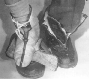
The A-6 winter shoes’ companion A-7 winter shoes (inserts) are displayed here. The A-6’s¾ in. thick fleece lining is visible.
The A-8 oxygen mask, as the A-7, was of the continuous flow type providing a steady oxygen flow regardless of the wearer’s needs. The oxygen flow had to be adjusted by the crewman with the pilot calling out the altitude. It was standardised on 1 May 1940. Highly prone to freezing, they were deemed unsafe early in the European bombing campaign and replacements were rushed to units. A 55 in. long,  in. diameter rubber hose connected the mask to the oxygen supply. The facepiece was held in place by a leather strap assembly secured around the nape of the neck; no modification was required to the helmet. It was issued in only one size. In cold weather or at extremely high altitudes, a dark OD wool-lined cotton shield assembly was required to protect the bag from freezing. Due to the A-8’s problems, modifications were undertaken resulting in the A-8A standardised on 13 February 1941, the A-8B of 3 November 1941, and the A-8C of 26 January 1945. An attempt was made in 1945 to convert A-8B masks to a demand type, but was only marginally successful. These later A-8s were used only in cargo aircraft.
The A-9 oxygen mask, standardised on 9 December 1941, was improved over the A-8 masks in that it was of the straight demand regulator type—i.e. it would supply a flow of oxygen as required by the wearer due to increased activity; a diaphragm-operated flow valve in the oxygen system’s regulator supplied the flyer with the proper mixture of air and oxygen according to altitude every time he inhaled, and shut off when he exhaled. The A-9 was made in two sizes, short and long. Its poor fit resulted in it seeing only limited use through early 1942.
One of the most widely used masks was the A-10 oxygen mask standardised on 20 April 1942. It was similar to the A-9 in operating principle and appearance, but slightly improved. Procurement of the A-10 was rushed in 1943 as bomber crews in England were still using the deficient A-8. Several improvements were incorporated in the A-10 during the war. An early modification was the A-10 (converted) of mid-1942. The A-10R (Revised) was adopted in late 1942 to be followed by the A-10A in October 1943. The A-10 and A-10A came in three sizes, small, standard, and large. The A-10R was issued in four sizes with the addition of extra small. Limited use was made of the AN-M-3 (AN6001–1) oxygen mask standardised on 1 July 1943 to replace the A-10, to which it was similar. This joint Army-Navy mask was reclassified as limited standard on 15 October 1943 when the A-10A was standardised. (The A-11 and A-12 masks of 1943 were experimental plastic oxygen helmets.)
The A-14 oxygen mask, standardised on 1 July 1943, offered greater improvements over the A-10R including more reliable operation and simpler construction, and was less prone to freezing, which still plagued the earlier types. It was first issued to the Eighth AF in early 1943, prior to its standardisation, to replace all earlier types. However, it was found that A-14s still froze. This problem was corrected by a simple modification and most had been fixed by late 1944. The further improved A-14A was standardised on 27 January 1945. They were issued in three sizes, small, medium, and large.
The A-13 oxygen mask was procured on a limited basis in January 1944 as the standard pressure-demand breathing mask to permit ascent above 40,000 ft. It was designed to hold positive pressure without leakage until the wearer exhaled. The improved A-13A was standardised on 28 August 1944. These were used by high-altitude photo-reconnaissance pilots and B-29 bomber crews in lieu of the A-14. However, though designed to fit a wider range of face sizes, they proved to be too tight-fitting on many men, obstructed vision by protruding too far from the face, and made it difficult to speak due to the internal pressure. The A-15A oxygen mask (the A-15 was tested, but did not see service) was an improved version of the A-13A and differed only in suspension, a better fit, internal refinements, and could also be used as a demand mask. It saw service use from May 1945, but was not standardised.
With the exception of the A-7 and -8, these masks required the installation of special snaps to flying helmets for attachment. All demand masks used corrugated oxygen supply tubes fitted with standard quick-disconnect connectors. The A-7 and -8 masks had no integral microphones. The A-9 used either MC-253 or -254 microphones. All other models used either the T-42 (carbon), T-44 (magnetic), or ANB-M-C1 (carbon). With the A-8, and in aircraft not needing oxygen masks, a T-30 throat microphone was used.
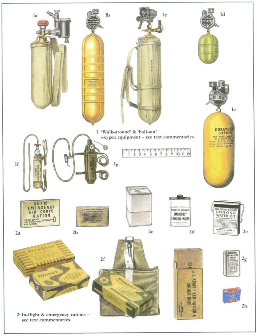
Aviator’s breathing oxygen cylinders of many capacities were fitted inside aircraft. These were orange-yellow painted, stainless steel cylinders with ‘BREATHING OXYGEN’ stencilled in black along with capacity and pressurisation instructions. Cylinders were of two types, high- and low-pressure. High-pressure cylinders posed a hazard when struck by bullets or flak fragments resulting in an explosion throwing out steel shards, and were also a fire hazard. The AAF ceased the development of such cylinders in 1942 and began to use low-pressure types1. Early low-pressure cylinders were made of stainless steel reinforced by external strapping which sufficiently supported the cylinder to withstand impact by a .50-cal. bullet. In 1943 low-alloy steel cylinders were developed that eliminated the need for the strapping, were even less affected by gunfire, and marked ‘NON-SHATTERABLE’ since they looked like the old high-pressure types.
Portable or ‘walk-around’ cylinders permitted an airman to move about at high altitudes in parts of the aircraft remote from fixed oxygen facilities and beyond reach of extension hoses. The airman disconnected his mask hose from the demand regulator at his crew station and inserted it into the walk-around cylinder’s connector. The low-pressure models could be recharged by inserting the regulator spud into a filling valve from the airman’s walk-around unit recharger assembly located at his station. (High-pressure and bail-out bottles had to be refilled by ground maintenance personnel.) They were also used to provide emergency oxygen to wounded crew and to revive those in an anoxic state; continuous flow equipment was considered better for this purpose. They were also used in event of failure of the main oxygen system and even for escaping from an aircraft underwater. Walk-around cylinders were painted orange-yellow and had black markings, though the A-4 cylinder, used with the AN6020–1 unit, was green.
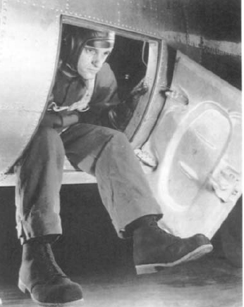
B-17 tail gunner emerging from his escape hatch wearing the dark grey F-2 electric heated flying felt shoes, with tan composite material soles and heels. He is wearing the F-2 electric suit’s outer jacket and trousers.
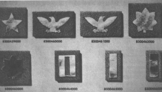
‘Leather insignia’, actually flat metal cut-outs mounted on russet leather tabs, for wear on the shoulders of flying jackets. All are silver-coloured except major and 2nd lieutenant which are gold-coloured. Their stock numbers are shown beneath. (Top, 1. to r.): Brigadier General, Colonel (left shoulder), Colonel (right shoulder), Lieutenant Colonel. Bottom: Major, Captain, 1st Lieutenant, 2nd Lieutenant.
The 1939 high-pressure continuous flow walk around assembly was comprised of a 96 cu. in. (internal volume) A-2 high-pressure cylinder coupled with an A-8A regulator and a walk-around sling, a light OD canvas cylinder-shaped bag and carrying strap. With the introduction of demand type masks, it was found that this assembly provided only two to five minutes of oxygen at 25,000 ft. rather than the required 30–45 minutes.
To provide sufficient oxygen a new assembly, the low-pressure continuous flow walk around assembly, was issued in 1942. It was made up of a much larger 500 cu. in., banded D-2 low-pressure cylinder and an A-9A regulator along with a walk-around sling, and was generally slung across the back. It was good for 30 minutes at 25,000 feet.
An improved version of this type of assembly was issued in early 1944. The low-pressure demand walk around assembly, or cylinder and sling assembly-portable oxygen, consisted of a D-2 low-pressure cylinder with an A-13 regulator. It used the same sling and had the same duration as the continuous flow version.
The early 1942 AN6020–1 low-pressure demand walk around unit, or cylinder and regulator assembly-oxygen portable, was composed of a 104 cu. in. A-4 low-pressure ‘football’ cylinder and A-13 demand regulator. This small unit had a clip allowing it to be attached to the jacket. It lasted only six to twelve minutes due to its small size and lack of a diluter regulator; it was replaced in 1944 by the following unit.
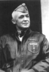
Maj.Gen. Henry H. ‘Hap’ Arnold, later commanding general of the USAAF, demonstrates the wear of unit insignia (printed on a leather patch) and leather name plate on the A-2 jacket.
The regulator and cylinder assembly-diluter demand oxygen was made up of an A-15 diluter demand regulator and a non-shatterable, 280 cu. in. A-6 low-pressure cylinder. It held a 30-minute oxygen supply, in spite of its small size, because of the diluter feature. It had a clip to attach it to the flying jacket.
Emergency, or bail-out, bottles enabled an airman to take an oxygen supply with him in event of bail-out between 25,000 and 40,000 ft. They were carried in a dedicated pocket on the left side of the flying trousers and also provided with a duck carrying sling with tie-tapes to strap it to the thigh or parachute harness leg strap. A tube storage pocket was part of the sling assembly. Both types included 20 cu. in. high-pressure bottles holding eight to ten minutes of oxygen and were painted green with black markings. They had a pressure gauge and a 2 ft. rubber tube; there was no regulator.
The H-1 emergency oxygen cylinder assembly, standardised on 2 October 1941, had a pipe stem on the tube’s end. This was thrust under the airman’s oxygen mask into the corner of his mouth and between his back teeth. The oxygen flow was started by a hand-operated valve prior to bail-out. The mask was not to be removed until the airman had descended to a lower altitude. The time and effort to properly insert the pipe stem and manually turn on the flow during a frantic emergency bail-out caused difficulties for many.
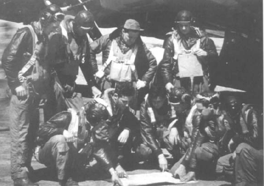
This B-17G crew demonstrate the diversity of clothes and equipment used by a single crew. No attempts were made to standardise clothing within crews or units.
The H-2 emergency oxygen cylinder assembly was similar to the H-1 but had a non-shatterable cylinder, metering device, and a pull-cable oxygen release fitted with a green-painted wood ball-handle (‘green apple’). It was standardised on 20 April 1943. An adaptor was issued with the assembly that fitted between the face-piece and hose of demand masks. The H-2’s hose was snapped into the adapter prior to take-off and the cable release simply yanked to begin the oxygen flow upon bail-out.
By early October 1942 sufficient data had been collected on projectile wounds among US bomber crews in England to establish that about 70% of the casualties were caused by low velocity projectiles, namely flak fragments and secondary missiles (aircraft structural components, plexiglass, etc.). Brig. Gen. Malcolm C. Grow, Eighth AF Surgeon (later Surgeon General of the US Air Force), became the prime motivating force behind the development of flyers’ body armour1, and many other initiatives aimed at improving the protection and effectiveness of airmen.
Development of flyers’ body armour, or ‘flak suits’, was begun by the Eighth AF in October 1942. By March 1943 test sets of armour were provided to 12 B-17 crews and the results were encouraging. The Eighth AF commanding general indorsed Gen. Grow’s recommendation that the armour be adopted. The Wilkinson Sword Co. produced 600 sets in Britain while much larger contracts were let in the States. The British-produced armour was not available until August 1943, and US production was rushed to meet the demand for enough armour to equip 60% of the Eighth and Ninth AF bomber crews. The body armour was maintained in unit pools and issued to crews prior to a mission and turned in upon return. This 60% figure was the ratio of bombers usually available for operational missions at any one time and enabled all crewmen to be outfitted with a flak suit. By January 1944 the suits had been issued to the Eighth and Ninth AFs in Europe, the Twelfth and Fifteenth in the Mediterranean area, and the Fifth and Thirteenth in the Pacific (where its wear was less common due to a limited flak threat), followed later by the Twentieth AF with its B-29s. The wearing of flak suits and steel helmets reduced fragmentation and bullet fatalities by about 50% and injuries by 70%. Well over half the individuals struck by missiles while wearing armour survived unscathed.
There was initially much resistance to wearing the suits due to their weight and restriction to movement. Some crewmen stood or sat on the vests rather than wearing them, under the mistaken impression that most fragments penetrated the aircraft from below; side penetration was actually much more common. Intensive training, distribution of ‘satisfied customer’ statements by men wearing vests when hit, and surgeons’ reports, accompanied by explicit photos, along with practical experience, eventually convinced most crews that the fatigue and discomfort caused by the suits was worth it.
The suits were made of overlapping 2 in. sq., 0.045 in. (20 gauge) thick Hadfield manganese steel plates sewn into pockets lined with a white cotton fleece-like fabric and covered with light or dark OD duck (early British-made suits were white). Early suits had a list of what crew positions wore which suit components, by type of aircraft, printed on the front. The vests were large enough to be worn over back type parachutes, and were fitted with a quick release system attached by web tapes to shoulder releases. Pulling a red web strap at the midriff caused the entire suit assembly to drop away, allowing the unencumbered flyer to exit the aircraft.
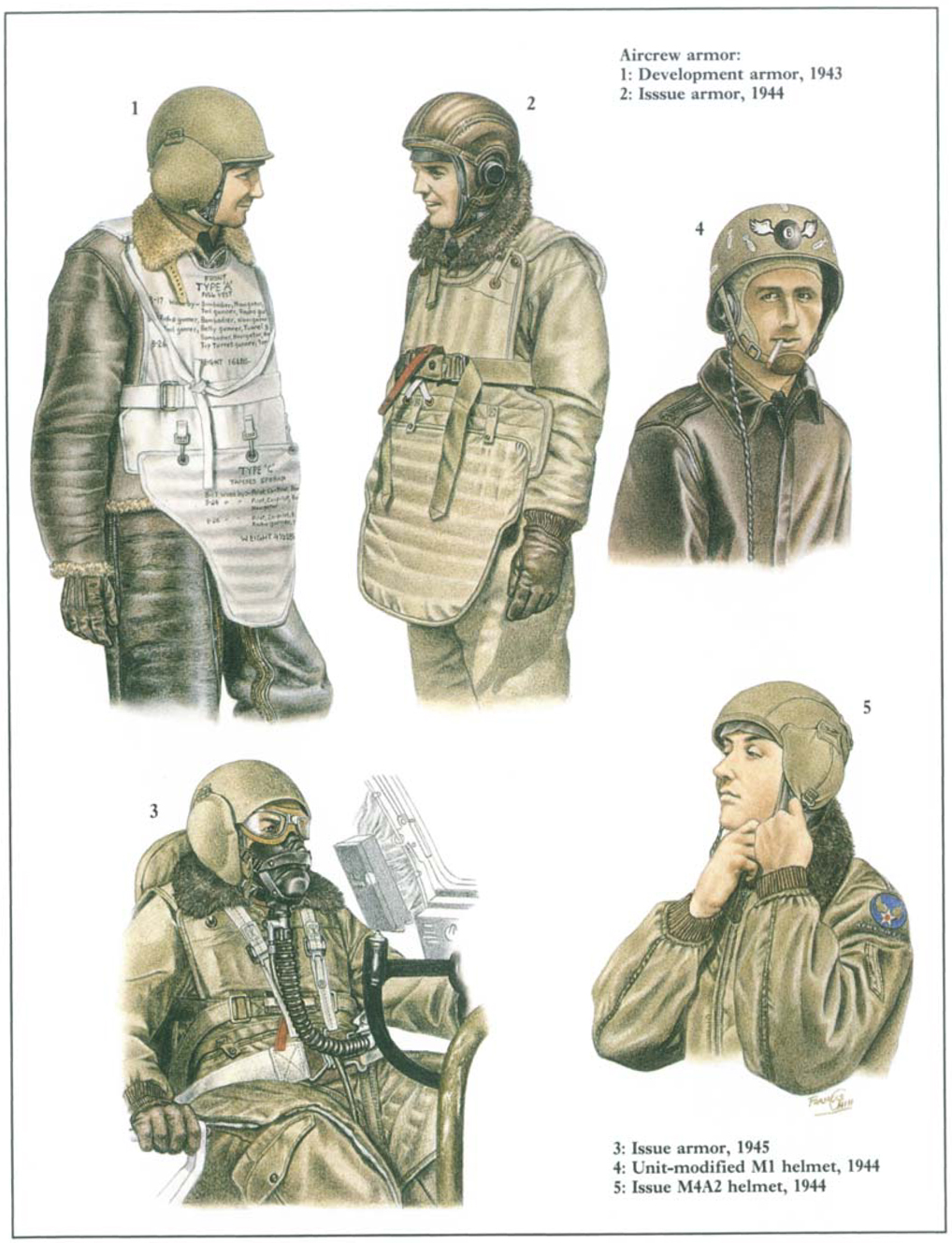
Four body armour components were initially made available. Which components were worn by a specific individual depended on his crew position. British-made components were designated ‘type’ followed by ‘A to D’. The initial US-made components were designated ‘T’ (Test) followed by ‘1 to 4’. On 5 October 1943 the test components were standardised and redesignated with an ‘M’ (Model) followed by the same number. The weights given are for the standardised models, earlier versions’ weight varied slightly either way.
The M1 flyer’s armour vest was a 17 lb. 6 oz. vest with fully armoured front and back for use by bombardiers, navigators, radio operators, waist and tail gunners plus top turret gunners in some aircraft: individuals exposed to injury from the front and back. Pilots and co-pilots1 wore the 7 lb. 13 oz. M2 flyer’s armour vest, which had the M1’s armour front panel, but its back was unarmoured since pilots were provided armoured seats. Attached to the M1 and M2 vests, by three small snap hooks and ‘D’ rings, were either the M3 or M4 flyer’s armour apron. The 4 lb. 14 oz. M3 was a triangular ‘sporran’ designed to protect the lower torso and groin areas of those in sitting positions or required to move about in confined spaces. It was worn by pilots and co-pilots, bombardiers and some other crew positions depending on aircraft type. The 7 lb. 2 oz. M4 apron provided more frontal protection with its square shape and was worn by waist gunners and others.
The M5 flyer’s groin armour was introduced in 1944 to provide even more lower body protection than the M3 and M4 aprons. It was a 15 lb. 4 oz. assembly made up of three sections: the centre section could be drawn between the legs while the thigh sections protected the outer sides of the legs and extended to the knees. It was used by pilots and waist gunners.
In late 1944 a new series of flyer’s armour was developed. Although of the same basic design as earlier models, the new series were made of hardened aluminium plates and ballistic nylon. They were considerably lighter, e.g. the M6 vest was almost three pounds lighter than the similar Ml. The series was standardised on 1 July 1945, but only a small number of M6 vests were issued to Twentieth AF B-29 crews. The M6 and M7 flyer’s armour vests were comparable to the M1 and M2 while the M8 and M9 flyer’s armour aprons were equivalent to the M3 and M4 aprons. The M10 flyer’s groin armour was similar to the M5.
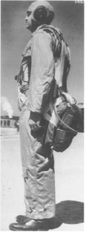
The S-5 seat parachute was the only type with the wide chest band (on the left side only) supporting the ripcord handle assembly. Its seat cushion is visible. The airman wears an A-10A summer helmet and AN-S-31 summer suit.
B-8 back parachute assembly with the older B-7 harness. Such mixed parachute assemblies were usually interim designs.
A wide range of experimental body armour components were tested, but only one saw wide service use. The T44 neck armour was widely field tested in early 1945 and proved effective. The 4.5 lb. ‘Queen Anne’ T44 was worn in conjunction with the M1 and M2 vests and M4A2 steel helmet. It did restrict vision and head movement somewhat as it was required to be snapped to the helmet. It protected the throat and the head’s sides and back.
Armoured helmets were developed in conjunction with, but as separate components of, body armour. The principal problems with steel helmets were interference with headsets, goggles, and masks: and some turret designs precluded their use due to confined space. Nevertheless, head wounds contributed to a very large percentage of fatal and severe injuries.
Initially, all bomber crewmen were issued standard Hadfield manganese M1 steel helmets and M1 helmet liners, made of thick, pressed, plastic impregnated duck, as used by ground troops since 1941. These were seldom used as they were almost impossible to wear with headsets and goggles though they were sometimes worn reversed to accommodate goggles). Several unit-initiated attempts were made to modify the M1 helmet to better accommodate these accessories, usually by cutting off the helmet’s lip visor to accommodate goggles and/or making semicircular cutouts in the sides for the headset. A moderately effective method was devised in the autumn of 1943 to spread the helmet and cut out sections of the liner for the headset. Steel helmets were also worn directly over shearling flying helmets without the benefit of the liner; this reduced protection against blunt trauma injury. The need for helmets was critical and British flyers’ steel helmets were issued to some bomber crews in 1943. (The following helmets’ test designations are included.)
The 3 lb. 3 oz. M3 steel helmet (T2) was the first dedicated flyers’ steel helmet. Standardised in December 1943, it was a modified M1 with the addition of hinged armoured ear protectors covering the headset cutouts.
In mid-1943 the ‘Grow helmet’ (named after its designer) was issued to some Eighth AF bomber crews. Modelled after the British flyers’ steel helmet, it comprised Hadfield steel plates lined with fabric and covered with dark brown leather. It was a simple dome-shaped helmet with headset cutouts and a leather chin strap assembly. Though the Grow helmet’s ear and temple area was exposed, it was standardised on 2 December 1943 as the M4 steel helmet (T3) to supplement the M3. It weighed 2 lb. 1 oz. The much improved M4A1 steel helmet (T3E3) had hinged steel ear protectors similar to the M3’s. Standardised in April 1944, only small numbers of these were made. It was replaced in June 1944 by the more widely issued M4A2 steel helmet (M4E2). It was made slightly larger to accommodate more head sizes and better integrate with masks and goggles. The M4A1/A2 helmet bodies and ear protectors were covered with duck and had web chin straps. The improved helmets were authorised for wear by all crewmen of medium, heavy and very heavy bombers, troop carrier transports, and gliders. Fighter pilots seldom, if ever, used steel helmets.
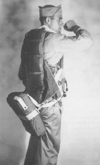
A B-8 back parachute with a C-2 one-man parachute raft case attached in the seat position, probably a test version. This staff sergeant also wears a B-4 life vest and C-1 emergency vest.
The M5 flyer’s armored helmet was standardised on 9 March 1945, though a slightly different test version, the T8 flyer’s armoured helmet, was issued in November 1944. The M3 helmet retained the general profile of the M1, but the M5’s size and profile was especially designed for use in confined turrets. However, it could not be worn by A-20 upper turret and B-29 central fire control gunners due to those positions’ extreme confinement. The M4A1/A2 and M5 helmets weighed 2 lb. 12 oz. The M1, M3, and M5 were painted dark OD inside and out.
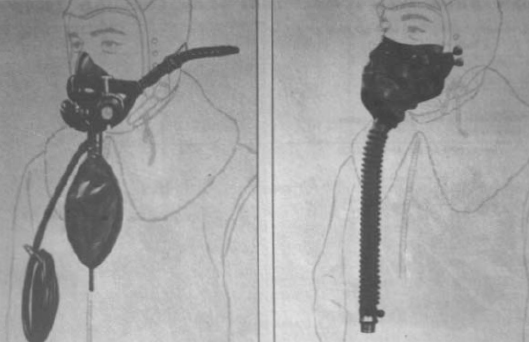
(Left): The A-8B oxygen mask, recognisable by its rebreather bag. This continuous flow mask was extremely prone to freezing and was phased out in 1942. (Right): The A-10 oxygen mask, similar in appearance to the A-9, was made in four variants.
Several types of crew first aid kits were available aboard aircraft and as a component of some types of E-series survival kits and multiplace life-rafts. Others were intended for individual airmen.
The 1942 parachute first aid kit No. MD 9710600 (‘frying pan insert’) was issued with the B-2, -3, and -4 parachute pad emergency kit assemblies (see Emergency Kits). Its small OD painted, circular, flat metal can contained compresses, sufadiazine (anti-infection-’sulfa’) tablets and powder, halazone (water purification) tablets, antiseptic, atabrine (anti-malaria) tablets, and boric acid (eyewash).
The parachute first aid packet No. MD 9778500 was originally issued to paratroopers (often seen fastened to the helmet net), but two were also provided to airmen in 1943 to attach to their parachute harness right shoulder strap for emergency treatment while airborne or after bailout. The 5 oz. waterproofed OD cloth, rubber-lined packet was fitted with two tie tapes and opened by tearing off either end. It contained a field dressing, tourniquet, and morphine syrette.
The aeronautic first aid kit No. MD 9776500 was standardised in late 1943 by the AAF, US Navy, and British Joint Aeronautic Board. It comprised a two-compartment OD duck container fitted with lift-the-dot snaps to fasten it to matching studs fixed at aircraft crew stations. It was issued on the basis of one kit per two crewmen or one per man at an isolated station. It was also a component of the E-8, -11, and -12 emergency kits. A small snap closed compartment contained adhesive bandaids and iodine swabs to treat minor cuts. The large zipper-closed, double compartment was sealed and intended to be broken only in case of severe injury. It contained three field dressings, compresses, tourniquet, eye-dressing and burn-injury sets, morphine syrettes, sufadiazine powder or tablets, halazone tablets, and scissors.
The individual aircrew member first aid packet No. MD 9714000 was available to all airmen, but was principally used by fighter pilots when the aeronautic first aid kit was removed from fighters in early 1945; the latter’s components were difficult to use for self aid. The new kit held a field dressing, tape, burn ointment, two morphine syrettes, sufadiazine tablets and powder, halazone tablets, antiseptic, and safety pins, all contained in a 6×4½×1½ in. aluminium box. An improved model, the A-1 individual aircrew member first aid packet, was standardised in March 1945.
The 1944 C-1 flyer’s emergency sustenance vest first aid kit was contained in a small OD plastic box. It held two compresses, four bandaids, burn ointment, two morphine syrettes, and vials of sufadiazine, atabrine, halazone, salt, and benzedrine tablets.
The life raft first aid kit No. MD 9776900 was issued with the AN-R-2A one-man life raft and multiplace rafts. Packaged in a sealed, waterproofed pasteboard box, its contents were similar to those of the aeronautic first aid kit’s, but were not as complete.
The electric heated casualty bag was developed by the Eighth AF’s Central Medical Establishment in 1943. It was made in the form of a roomy, ‘mummy’-type sleeping bag with multiple layers of OD fabric in both 12 and 24 volt versions. Wounded flyers were placed in the bag to protect them from high-altitude cold and to prevent shock. It could also be used to transport a wounded man and in event of ditching at sea, would keep him afloat for 15–20 minutes. Four were carried in heavy bombers. This bag was replaced by the standardised 24 volt Q-1 electric heated casualty blanket in 1944. It was of a similar but improved design (including a rubber lining) and would keep a casualty comfortable between 40° and –40°F.
The electric heated muff was also developed by the Eighth AF in 12 and 24 volt versions. It was a dark OD cloth-covered affair with internal heating wires; knit wristlets were fitted on both open ends. Five were carried in heavy bombers for use if electric gloves or boots failed; they could be slipped over a foot as well as the hands.
A number of large type E-series emergency sustenance, or survival, kits were available either for carriage in aircraft for use after a forced landing or for dropping to downed crews when located by search aircraft. Navy issue kits were also used by the AAF. The kits were designed for use in specific areas (arctic, desert, tropic, ocean) and contained rations, canned water, specialised clothing, tools, signal items, medical supplies, and other survival aids. Some even contained an over-and-under .22-cal. rifle/.410 shotgun or .30-cal. M1 carbine. Their size and container styles varied greatly, and the number and type of kits stocked in an aircraft depended on crew size and area of operations. Besides the larger kits, there were several available that could be attached to an airman enabling him to take it with him during bail-out.
The E-3 emergency sustenance kit was a personal aids kit standardised on 10 June 1942. It was simply a small plastic box held in an OD cloth bag, secured by a drawstring and small enough to fit in a pocket. It held matches, bouillon powder, chewing gum, malted milk and halazone tablets, ‘button’ compass, hacksaw blade, and tape.
The E-6 (rations) and E-7 (water) emergency sustenance kits (individual bail-out) each comprised a small rectangular, two-pocket OD duck pouch with a buckled white web securing strap and snap hook for fastening it to the parachute harness. The E-6 held two K ration meals while the E-7 held two AN-W-5 emergency drinking water cans. Standardised on 27 November 1943, these kits proved not to be of much use and few were procured.
The E-17 emergency sustenance kit was another personal aids kit procured from the Military Intelligence Service. It was standardised on 31 July 1944. It was contained in a stout dark OD duck 6×4¼×3in. pouch secured by a flap with two lift-the-dot fasteners; the back was fitted with two web loops plus a belt double hook. Inside were carried an ESM/1 signal mirror and two clear ethyl cellulose flasks. These had a clip-on lid with a screw-on cap enabling it to be used as a water canteen. One flask contained candy, chewing gum, bouillon powder, matches, fishing hooks and line, ‘button’ compass, hacksaw blade, razor blades, and condoms (to waterproof small items or carry water). The other flask held a toothbrush, tweezers, tape, bandaids, antiseptics, and six types of medication tablets.
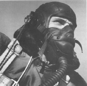
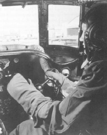
Details of the A-14 oxygen mask retaining strap assembly, shown here along with the A-11 intermediate helmet and B-9 winter jacket.
The E-3A emergency sustenance kit was a personal aids kit procured from the Military Intelligence Service. It was standardised on 6 April 1945. Of a much different design than the E-3, it was contained in a single flask as used in the E-17 kit. Packed inside were matches, bouillon powder, candy, antiseptic; benzedrine, sulphate, halazone and aspirin tablets, a hacksaw blade, and tape. Though widely issued to airmen as an ‘escape’ kit, it was of little value and was replaced by the C-1 emergency vest.
Parachute emergency kits replaced standard back or seat pads on parachute harnesses. These 7–8 lb. kits had a pad/container covered with OD duck encasing layers of thick felt with cut-outs for survival items; a zipper ran around the containers’ edge. Their contents varied according to area and often changed as the AAF’s Arctic, Desert and Tropics Information Center redefined kit specifications. The rations were originally two emergency Air Corps rations, replaced later by two K-ration meals, and still later by emergency parachute rations (see commentary Plate K2).
The B-1 Alaskan parachute emergency supply kit was a back pad for seat parachutes, standardised on 7 August 1941. Its contents were meagre compared to other kits’ and it was not considered very effective: .45-cal. ball ammo, compass, cooking pan, D-2 gloves1, fishing tackle, rations, and limited first aid items.
The B-2 and B-3 jungle parachute emergency kits were a back pad for seat parachutes and a seat pad for back parachutes respectively. Their contents were similar: .45-cal. ball and shot ammo, compass, flare kit, fishing tackle, frying pan, first aid kit, medications, rations, D-2 gloves, mosquito headnet, and folding machete. The B-2 was standardised on 16 January 1942 and the B-3 on 12 June 1942.
The much improved B-4 parachute emergency kit assembly was a seat or back pad for back and seat parachutes respectively. It was standardised on 7 October 1942 for arctic, desert, and tropical regions. However, it was not issued until late 1943 as earlier kits had to be expended first. Its extensive contents included: .45-cal. shot ammo, compass, collapsible canteen, cooking pan, insert first aid kit, D-2 gloves, H-1 goggles, pocket knife, folding machete, matches, poncho, flare, signal panel, signal mirror, and rations. The limited issue B-5 parachute emergency kit assembly was similar, but intended for seat type parachutes and had improved contents. It was standardised on 12 April 1944, but the cases carried the B-4 kit markings.
The parachute emergency kits were replaced by the C-1 vest, on which development began in early 1943. Some units in the Pacific had earlier developed their own survival vests and these influenced the design of the C-1. The parachute kits also often remained in use, usually with their contents modified by their users.
The C-1 flyer’s emergency sustenance vest was standardised on 3 May 1944, though it saw only limited issue beginning in late 1944. Developed for use in all parts of the world, it was better suited for the tropics than the arctic. Its contents were designed to complement those of the C-2 life raft. The vest was made of dark OD tackle twill and fitted with zippered or snap-closed box pockets. Three large plastic buttons secured the front opening, and it was sized by tie tapes on the back. There were three different size pockets on both sides of the front torso, a smaller pocket on the right front shoulder, three small pockets on the right side, and a duck, leather-lined or all leather pistol holster on the left side. Variants will be found with slightly different pocket arrangements; early vests had the pockets’ contents and number printed on them. A ‘subdued’ or white AAF insignia was printed on the left front shoulder. The pocket layout was designed to allow the vest to be worn under the parachute harness and life vest. The vest was also carried in a modified M1936 field bag (musette bag) attached to the left side of a parachute harness. The 11 lb. vest contained: .45-cal. shot ammo, fire starting kit, first aid kit, fishing/sewing kit, gloves and inserts, H-1 goggle, reversible hat (yellow/OD), mosquito headnet, insect repellent, pocket knife, sharpening stone, two emergency parachute rations, two signal flares, ESM/1 or 2 signal mirror, spit and gaff assembly, M1943 collapsible canteen, collapsible asbestos cooking utensil, and other small survival aids.
The B-3 and B-4 pneumatic life preserver vests, almost identical in design, were commonly known as the ‘Mae West’. They were of the horse-collar style designed to keep a man’s head above water even if unconscious; they could not keep a man in full flying clothes afloat, however. Web waist and crotch straps secured the vest to the wearer. The B-3, standardised on 8 January 1938, had double compartments made of cotton fabric encasing two separate latex rubber bladders. The Navy-designed AN-V-18 vest was standardised by the Army as the B-4 on 6 May 1942. It had two superimposed compartments constructed from rubber-coated fabric; it was stiffer and less comfortable than the B-3, but simpler to manufacture and used less rubber, now a scarce commodity. The B-4 was redesignated the AN6519–1 vest on 1 February 1944. Navy ANV-18 vests were also used by the AAF. All variations had orange-yellow casings and straps and were inflated by two pull-cord activated 0.280 oz. CO2 cylinders near the bottom ends, or by a pair of oral inflation tubes on the right upper front.
The AAF-designed B-5 pneumatic life preserver vest was standardised on 12 December 1944 to replace the B-3/B-4, although they remained in use (the B-5 is still standard). Similar in appearance to the earlier types, it was of considerably different construction. It allowed the head to float up higher out of the water and kept the wearer more vertical, regardless of weight. It also had improved retaining strap and inflation systems. It weighed 3 lbs., the B-3/B-4 weighed four. Two snap-closed pockets were fitted between the flotation chambers for survival aids.
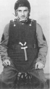
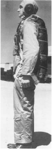
The M1 armour vest and M3 armour apron; the quick release strap on the midriff is red and the connecting webbing is white. An M4 steel, or ‘Grow’, helmet is worn over a shearling flying helmet.
Life jacket dye markers (yellow-green fluorscein dye) were often attached to the life vest’s left side by tie cords or rubber cement. These were approximately 5×5 in. packets opened by pull-tabs; there were several versions, all made of the same material as life jackets. Life vest shark deterrent packets held a cake of so-called ‘shark chaser’. The blue waterproof packet was torn open and the cake swished in the water making a blue-black cloud, which also doubled as a dye marker. The cake was attached to the packet by a tape and could be returned to the packet for reuse. They were attached to the right side of life vests between the chambers. The Navy issue life jacket attachable light was provided to AAF airmen. It was a small, single-battery, grey or orange plastic flashlight fitted with a safety pin for attachment to clothing.
Several four-man (types A-2, -3, -3A) and six-man (types E-1, -2, -2A) inflatable rubber life rafts were part of the on-board equipment supplied with bombers and transports, fitted in wing and upper fuselage pop-out compartments. A considerable amount of survival equipment and supplies were packed in these rafts. The only rafts we will discuss here are the one-man type that could be attached to parachute harnesses as an uncomfortable seat cushion. All models were packed in OD duck parachute pack cases. Small experimental rafts (B-1 and C-1) were tested prior to the war, but were not adopted due to bulk problems and storage space in fighters.
The AN-R-2 and AN-R-2A (AN6520–1) one-man parachute rafts were used by fighter pilots and bomber crews flying overwater routes. This 66 in. long, 40 in. wide (inflated) raft was made of two-ply orange-yellow rubberised fabric. It was inflated by a ¾ lb. CO2 cylinder, but also had an oral inflation tube. The 16 lb. raft and pack case contained a can of drinking water, paulin sheet (reversible blue/yellow and used for shade, weather protection, signalling, camouflage, catching rain water), sea anchor, bailing cup, hand paddles, raft first aid kit, raft repair kit, orange-yellow sail, and sea marker dye. The AN-R-2 was standardised by the AAF on 4 July 1942. The differences between the two models was the case. The Navy-designed AN-R-2 case had a slot in the centre for the parachute harness’s leg straps. This did not fit AAF harnesses well and the AN-R-2A case, standardised on 20 August 1942, eliminated the slot.
The AN-R-2A was replaced by the similar C-2 one-man parachute raft standardised on 21 April 1944, although the former remained in use. The C-2 was slightly smaller and included the addition of a blue spray shield, new-type sail and collapsible mast, and an improved case totalling 22 lbs. The case was fitted with a 1 in. wide web static line that attached to the right side of the harness. The case could be released while the jumper was still airborne, automatically inflating the raft enabling him to board it immediately after landing. Its accessories were essentially the same as the AN-R-2A’s, but with the addition of an MX-137/A radar reflector, AN-CPT-2 radar beacon, M75 flares, ESM/1 signal mirrors, JJ-1 sea water desalting kit, and hand pump. The first aid kit was deleted, one being available in the C-1 emergency vest. The slightly improved C-2A one-man parachute raft was standardised on 21 May 1945.
* * *
A fully outfitted B-17 waist gunner wears a flak suit comprising the M1 vest and M4 apron. He wears the AN-H-16 winter helmet, A-14 oxygen mask (connected to an extension hose), and A-6 winter shoes.
A common complaint of flyers, particularly bomber crewmen, was that they felt like a Christmas tree when fully outfitted with layers of heavy clothing, electric heated suit, gloves, shoes, flying helmet, goggle, headset, oxygen mask, walk around and bail-out bottles, pistol, emergency kit or vest, life vest, life raft, parachute, steel helmet, and flak suit. All of this weighed close to 100 lbs.—a heavy load to bear in cramped quarters and fatigue-inducing cold while flying a plane or working its guns.
1 The US Navy, RAF, and Luftwaffe continued to use high-pressure equipment.
1 For further information on flyers’ body armour, see MAA 157, Flak Jacket.
1 Officially, bomber pilots were designated aircraft commanders and co-pilots were called pilots.
1 The D-2 mechanics’ gloves are described in USAAF Book 2.