
A New England school of arts and crafts is housed in a cluster of small buildings of wood light frame construction that cling to a dramatic mountainside site overlooking the ocean. (Architect: Edward Larrabee Barnes. Photo by Joseph W. Molitor.)
5
WOOD LIGHT FRAME CONSTRUCTION
Foundations for Light Frame Structures
Attaching the Frame to the Foundation
Lateral Force Resistance and Shear Walls
Upper-Level Floor and Wall Framing
Variations on Wood Light Frame Construction
Framing for Increased Thermal Efficiency
Framing for Optimal Lumber Usage
Prefabricated Framing Assemblies
Wood Light Frame Construction and the Building Codes
Uniqueness of Wood Light Frame Construction
HISTORY
Wood light frame construction was the first uniquely American building system. It was developed in the first half of the 19th century when builders recognized that the closely spaced vertical members used to infill the walls of a heavy timber building frame were themselves sufficiently strong that the heavy posts of the frame could be eliminated. Its development was accelerated by two technological breakthroughs of the period: Boards and small framing members of wood had recently become inexpensive for the first time in history because of the advent of the water-powered sawmill; additionally, machine-made nails had become remarkably cheap compared to the hand-forged nails that preceded them.
The balloon frame was the earliest wood framing system to be constructed exclusively of slender, closely spaced wooden members: joists for the floors, studs for the walls, rafters for the sloping roofs. Heavy posts and beams were completely eliminated and, with them, the difficult, expensive mortise-and-tenon joinery they required. There was no structural member in a frame that could not be handled easily by one or two carpenters, and each of the hundreds of joints was made with lightning rapidity with two or three nails. The impact of this new building system was revolutionary: In 1865, G. E. Woodward could write that “[a] man and a boy can now attain the same results, with ease, that twenty men could on an old-fashioned frame . . . . [T]he Balloon Frame can be put up for forty percent less money than the mortise and tenon frame” (Woodward, 1989, p. 164).
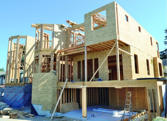
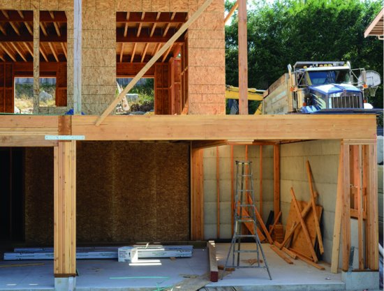
Figure 5.1 A wood light frame single-family home under construction. At bottom right is a concrete slab-on-grade garage floor. At the left, concrete basement walls have been covered with a dimpled plastic drainage mat. Exterior walls are framed with solid lumber 2 × 6 studs, sheathed with OSB panels. Floors are framed with I-joists (also with OSB subflooring not visible in this photograph). On top of the upper story walls, prefabricated roof trusses have been stacked in preparation for their installation. (Photo by Joseph Iano.)
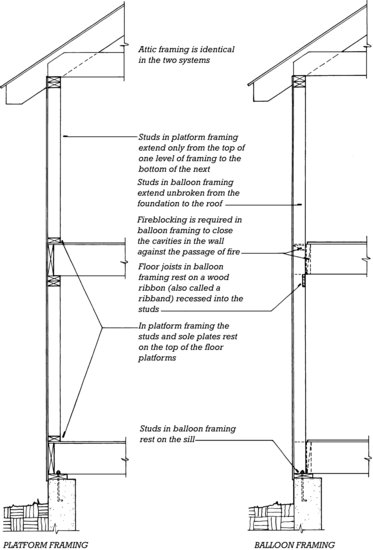
The balloon frame (Figure 5.2) used full-length studs that ran continuously for two stories from foundation to roof. In time, it became apparent that these were too long to erect efficiently. Furthermore, the tall, hollow spaces between studs acted as multiple chimneys in a fire, spreading the blaze rapidly to the upper floors, unless they were closed off with wood or brick fireblocking at each floor line. Several modified versions of the balloon frame were subsequently developed in an attempt to overcome these difficulties. The final, most successful of these, the platform frame, is now the universal standard for wood light frame construction.
Figure 5.2 Comparative framing details for platform framing (left) and balloon framing (right). Platform framing is much easier to erect and is the only light framing system used today. However, a platform frame settles considerably as the wood dries and shrinks. If nominal 12-inch (286-mm) joists are used to frame the floors in these examples, the total amount of loadbearing cross-grain wood between the foundation and the attic joists is 33 inches (838 mm) for the platform frame and only 4½ inches (114 mm) for the balloon frame.
PLATFORM FRAME
Although sometimes complex in its details, the platform frame is simple in concept (Figure 5.3). A floor platform is built. Loadbearing walls are erected upon it. A second-floor platform is built upon these walls and a second set of walls upon this platform. The attic and roof are then built upon the second set of walls. There are, of course, many variations: A concrete slab that lies directly on the ground is sometimes substituted for the ground-floor platform; a building may be only one story tall, or three or more stories in height; and roofs of various types are possible. The essentials, however, remain: A floor platform is completed at each level, and the walls bear upon that platform rather than directly upon the walls of the story below.
Figure 5.3 The concept of platform framing, shown in cross section, reading from left to right: A foundation wall is constructed. A ground-floor platform is framed and sheathed. Ground-floor wall frames are assembled horizontally on the platform, then tilted into their final positions. A second-floor platform is constructed on top of the ground-floor walls, and the process of wall construction is repeated. The attic floor and roof are added.


The advantages of the platform frame over the balloon frame are several: It uses short, easily handled lengths of lumber for the wall framing. Fireblocking is naturally provided by the platform construction at each floor level. Its platforms are convenient working surfaces for the carpenters who build the frame. The major disadvantage of the platform frame is that each platform constitutes a thick layer of wood whose grain runs horizontally. This leads inevitably to a relatively large amount of vertical shrinkage in the frame as excess moisture dries from the wood, which, if not properly accounted for, can cause distress in the exterior and interior finish surfaces.
A conventional platform frame is made entirely of nominal 2-inch members, which are actually 1½ inches (38 mm) in thickness. These may be ordered and delivered cut to the nearest 2-foot (600-mm) length, then measured and sawn to exact length on the building site. In larger-volume work, wall studs are frequently precut to the precise required length at the lumberyard and delivered to the site ready to install. Connections are made with nails, alone or in combination with metal connectors as required by the characteristics of each joint (Figures 3.42, 3.49, and 3.50). Nails are driven either by hammer or nail gun. In either case, connections are quickly made because the nails are installed without drilling holes or other time-consuming joint preparation.
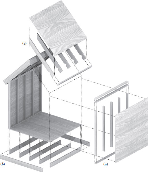
Each plane of structure in a platform frame is made by aligning pieces of framing lumber parallel to one another at specified intervals, nailing these to crosspieces at either end to maintain their spacing and flatness, and then covering the plane of framing with sheathing, a facing layer of boards or panels that join and stabilize the pieces into a single structural unit, ready for the application of finish materials inside and out (Figure 5.4). In the floor structure, the parallel pieces are the floor joists, and the crosspieces at the ends of the joists are called rim boards or band joists. The sheathing applied over the floor framing is called the subfloor. In a wall structure, the parallel pieces are the studs, the crosspiece at the bottom of the wall is the sole plate or bottom plate, and the crosspiece at the top (which is frequently doubled for strength) is called the top plate. In a sloping roof, the wall top plates play the role of the lower crosspiece and a ridge board is provided at the roof peak.
Figure 5.4 The basic components of platform frame construction. (a) Walls are framed with repetitive vertical studs, connected top and bottom by horizontal plates. (b) Floors are framed with repetitive joists connected at their ends by rim boards or band joists. (c) Sloped roofs are framed with rafters, with a ridge board at the peak. Every surface is sheathed, mostly commonly with plywood or OSB panels.
Openings are required in all these planes of structure, such as for windows and doors in the walls, stairs and chimneys in the floors, and chimneys, skylights, and dormers in the roofs. In each case, additional framing is required to support the ends of the shortened framing members. Openings in floors and roofs are framed with headers and trimmers (see Figure 5.15). For large openings, these members are doubled, to account for the higher loads they carry. In walls, sills head off the bottoms of window and door openings, while trimmer studs on the sides provide support to loadbearing headers across the tops (see Figure 5.32).
- A wood light frame building can be designed to minimize waste in several ways. It can be dimensioned to utilize full sheets and lengths of wood products. Most small buildings can be framed with studs 24 inches (610 mm) o.c. (on center) rather than 16 inches (406 mm). A stud can be eliminated at each corner by using small, inexpensive metal clips to support the interior wall finish materials. If joists and rafters are aligned directly over studs, the top plate can be a single member rather than a double one. Floor joists can be spliced at points of inflection rather than over girders; this reduces bending moments and allows use of smaller joists. Roof trusses often use less wood than conventional rafters and ceiling joists.
- Construction waste can be reduced by careful planning and ordering of the minimum quantity of framing materials, or by a greater reliance on panelized or modular construction systems.
- On the construction site, carpenters can waste less lumber by saving cutoffs and reusing them rather than automatically throwing them on the scrap heap. Scrap lumber can be recycled by shredding it for use in OSB production. Construction scrap should not be burned, because of the air pollution it generates.
- Structural composite lumber, I-joists, finger-jointed studs, and OSB sheathing are all materials that utilize trees more efficiently than solid lumber.
- Although the thermal efficiency of wood light frame construction is inherently high, it can be improved substantially by various means, as shown in Chapter 7. Wood framing is much less conductive of heat than light gauge steel framing. Steel framing of exterior walls is not a satisfactory substitute for wood framing unless the heat flow path through the steel framing members can be broken with a substantial thickness of continuous insulation on one side or the other of the framing.
Throughout the platform frame, the floor joists, wall studs, and roof rafters are consistently arranged so these members fall on a 4-foot (1220-mm) module. This ensures that standard 4-foot by 8-foot (1220-mm × 2440-mm) panels used to cover the inner and outer faces of the framing are readily supported at their ends (see, for example, Figure 5.17). Most commonly, framing members are spaced at 16 in. or 24 in. (406 or 610 mm) o.c.; o.c. or on center meaning that the spacing is measured from center to center of the members.
The sheathing, usually plywood or OSB (Figure 3.33) nailed over the outside face of the framing, is a key component, tying the various parts of the frame into a structural whole. In the wall frame, for example, the end-nailed connections between top or bottom plates and the studs, by themselves, offer little resistance to wind uplift forces acting on the roof. It is the wall sheathing spanning across these parts that provides the structural continuity needed to carry these forces from the roof to the foundation. Similarly, subflooring and roof sheathing provide important structural continuity to these parts of the structure. As discussed later in this chapter, structural sheathing plays a critical role in the platform frame's resistance to lateral forces exerted by wind or earthquake. Sheathing also furnishes a surface to which shingles, boards, and flooring are nailed for finish surfaces.
FOUNDATIONS FOR LIGHT FRAME STRUCTURES
Most residential and small commercial wood light frame buildings are built on shallow foundations consisting of spread footings, basement or crawlspace walls, and slabs on grade. Once these would have been constructed of stone or brick; today stronger, more durable, and more easily waterproofed steel-reinforced sitecast concrete and concrete masonry are the materials of choice. Examples of these foundation types are illustrated and explained in more detail in Figures 5.5, 5.6 through 5.12. For larger buildings (for example, multistory apartments) or where soil conditions close to the surface are problematic, deeper foundation types, as discussed in Chapter 2, may also be used.
 Figure 5.5 Step one in the construction of a simple platform frame building: establishing the location of the building on the site. After the corners of the foundation have been staked, batter boards are erected safely beyond the limits of the excavation area. String lines crossing over the corner stakes are stretched from the batter boards, and their positions on the boards are preserved with notches or nails in the boards. Later, after excavation, the strings are stretched again, and the foundation corners can be relocated at the bottom of the excavation. This figure begins a series of isometric drawings that will follow the erection of a wood light frame building step by step throughout the course of this chapter.
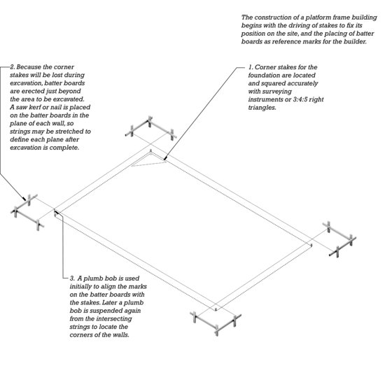
Figure 5.6 Typical details for a sitecast concrete foundation and basement for a platform frame building. Details A, B, and C are keyed to the circled portions of the drawing in Figure 5.7. You can download a PDF of this figure at http://www.wiley.com/go/aflblce6ne.
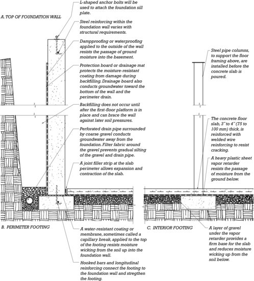
 Figure 5.7 Step two in the construction of a typical platform frame building: excavation and foundations. The letters A, B, and C indicate portions of the foundation that are detailed in Figure 5.6.
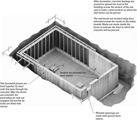
Figure 5.8 Example foundation insulation strategies. The amount of insulation required varies with the severity of the climate. Exterior cladding and interior finishes are not shown. Wall vapor retarders are shown in their most common location, on the interior (warm) side of the insulation. A. Foam plastic on the outside of foundation walls and under slabs on grade should be avoided where the risk of termite infestation is high. This material can provide concealed pathways for these insects between the ground and the building structure. B. When facing the building interior, foam plastic insulation must be covered with gypsum wallboard or some other fire-resistant material (not shown here) so that, in the event of a building fire, the release of toxic gasses from the foam plastic is delayed. The use of spray foam insulation, as shown at the rim joist here, is discussed in Chapter 7. C. This simple application of insulation batts to a heated crawlspace is suitable for a very mild climate. Other approaches, similar to those shown here for full basements, are also possible. D. When a crawlspace is ventilated to the exterior, the floor platform above must be insulated. Rigid insulation underneath the floor joists reduces thermal bridging and protects the joists and batt insulation from high humidity in the crawlspace. The foam plastic must be protected from direct exposure to fire (indicated here by the dashed line). Requirements for a vapor retarder over the soil depend on the amount of ventilation provided. E. When a slab on grade is connected to the foundation wall, insulation must be applied to the exterior. F. When the slab on grade and foundation wall are independent, insulation may be applied directly under and around the edges of the slab.

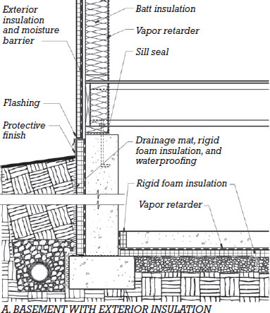
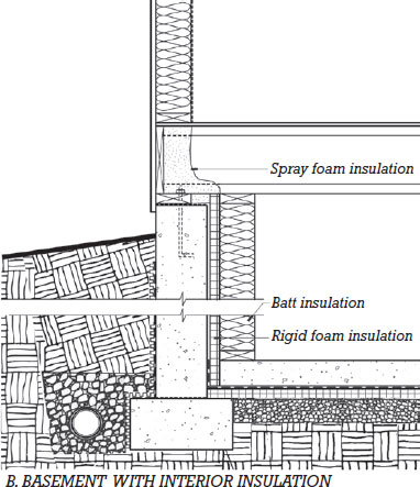
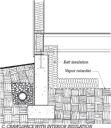
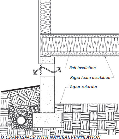
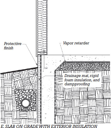
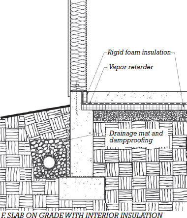
Figure 5.9 Masons construct a foundation of concrete masonry. The first coat of parging, which is portland cement plaster applied to help dampproof the foundation, has already been applied to the outside of the wall, and the drainage layer of crushed stone has been backfilled in place. The projecting pilaster in the center of the wall will support a beam under the center of the main floor. After a second coat of parging, the outside of the foundation will be coated with an asphaltic dampproofing compound. (Reprinted with permission of the Portland Cement Association from Design and Control of Concrete Mixtures, 12th ed.; Photos: Portland Cement Association, Skokie, IL.)
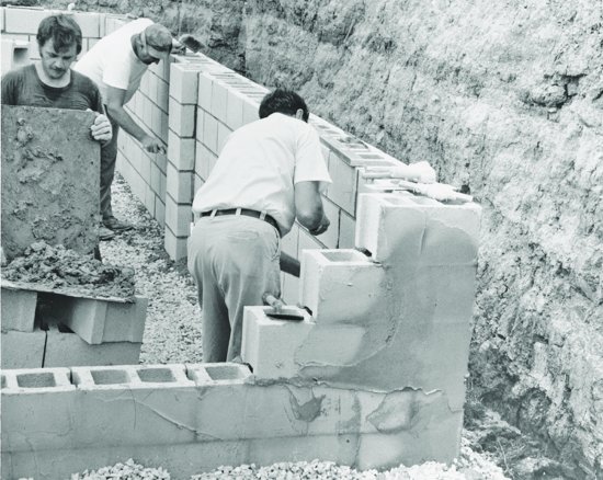
Figure 5.10 Erecting formwork for a sitecast concrete foundation wall. The footing has already been cast and its formwork removed. It is visible in front of the worker at the left. (Photo by Joseph Iano.)
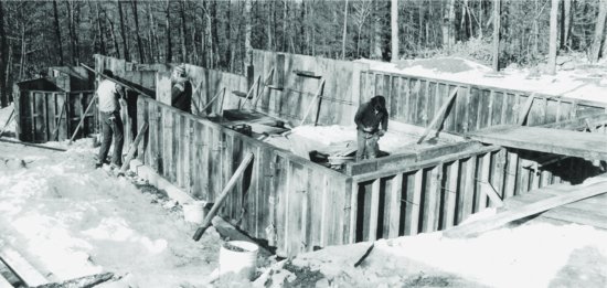
Figure 5.11 Concrete foundation work in progress. The foundation wall has not yet been cast on top of the spread footing in the foreground. In the background, crawlspace walls are complete. Openings in the walls will have louvers installed to provide natural ventilation for an unconditioned crawlspace. The rectangular spread footing within the crawlspace is for a masonry chimney. (Photo by Joseph Iano.)

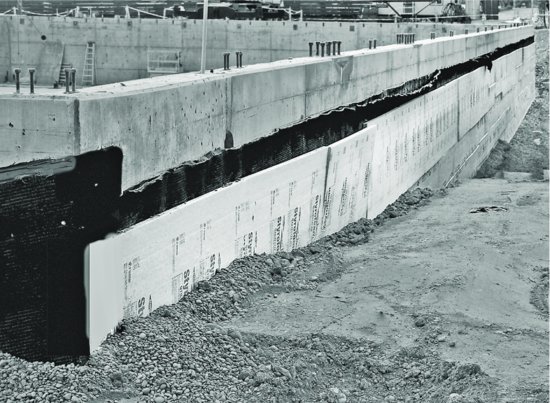
Figure 5.12 Concrete basement construction in progress. Anchor bolts are omitted from portions of the foundation wall where openings for doors or floor-level windows will be located in the wood framed wall above. Liquid-applied waterproofing and a drainage mat (both dark in color), and polystyrene foam insulation have been applied to the outside of the wall.
For simple basements and crawlspaces, protection from water entry usually takes the form of bituminous or cement plaster dampproofing applied to the outside of the foundation walls, along with drainage materials surrounding the basement walls and perimeter footing drains to draw water away (Figures 5.6 and 5.7). Where groundwater conditions are severe or there is a need to keep the basement interior as dry as possible, more expensive and resistant waterproofing treatments may take the place of dampproofing. Slabs on grade should be protected from moisture in the ground below by a heavy plastic sheet vapor retarder. In areas where radon soil gas is a concern, measures for protecting against the entry of this gas into the structure (also as discussed in Chapter 2) may be part of the foundation construction as well.
Energy conservation codes require foundations to be insulated to reduce the exchange of heat with the surrounding soil (Figure 5.8). Some insulation materials (such as boards made of rigid plastic foam or mineral wool) are unaffected by moisture and sufficiently dense that they can be placed on the outside of the foundation wall prior to backfilling or under a slab on grade before the slab is poured. Many more insulation types can be applied to the inside of the foundation. Crawlspaces may either be ventilated to the exterior or treated as part of the heated or cooled building interior. When ventilated, the floor above the crawlspace is insulated. When the crawlspace is conditioned (heated or cooled), its walls and floor are insulated in manners similar to those for a basement.
Other Foundation Materials
In extremely cold regions, where concrete and masonry construction methods are not practical, foundations may be made entirely of preservative-treated wood (Figure 5.13). Such permanent wood foundations can be constructed in any weather by the same crew of carpenters that will frame the remainder of the building. These foundations are readily insulated in the same manner as the frame of the house they support, and they easily accommodate the installation of electrical wiring, plumbing, and interior finish materials. Insulating concrete formwork (ICF) foundation systems using permanent insulating forms are easy to construct, eliminate the time and effort required to remove formwork, and provide integral insulation (see Figure 14.13). Precast concrete foundation systems relying on factory-fabricated reinforced concrete panels can be erected on site more rapidly than traditional sitecast concrete construction, although special attention is also required to seal the joints between adjacent panels. They may be manufactured with insulation integral to the precast panel or designed to accept insulation applied on site after the panels are erected.
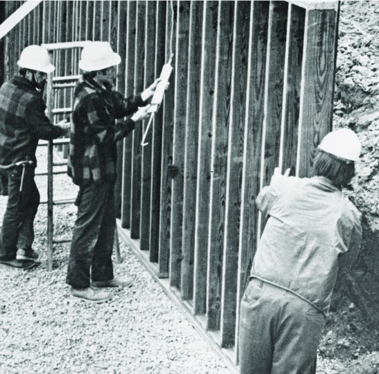
Figure 5.13 Erecting a permanent wood foundation. One worker applies a bead of sealant to the edge of a panel of preservative-treated wood components as another prepares to push the next panel into position against the sealant. The panels rest on a horizontal preservative-treated plank, which, in turn, rests on a drainage layer of crushed stone. Wood foundations can be constructed in any weather and can be insulated in the same way as the superstructure of the building. (Courtesy of APA–The Engineered Wood Association.)
BUILDING THE FRAME
Planning the Frame
An experienced carpenter can frame a simple building from the most minimal drawings, but the framing for a larger or custom-designed structure may have to be planned as carefully as for a steel or concrete structure (Figure 5.14). The architect or engineer determines an efficient layout and the appropriate sizes for joists and rafters, and communicates this information to the carpenters by means of framing plans (Figures 5.15 and 5.52). For most purposes, member sizes can be determined using standardized structural tables that are part of residential building codes. Or, for more complex framing or special conditions, project-specific engineering may be required. Larger-scale section details, similar to those seen throughout this chapter, are prepared for major connections in the building system. The architectural floor plans indicate the locations and dimensions of walls, partitions, and openings, and the exterior elevations show the outside faces of the building, with vertical dimensions or elevations indicated as required. For most buildings, building sections are also drawn that cut completely through the building, showing the dimensional relationships of the various floor levels and roof planes and the slopes of the roof surfaces. Interior elevations are often prepared for kitchens, bathrooms, and other rooms with elaborate interior features.
Figure 5.14 A floor plan and building section are two important components of the construction drawings for a simple house with wood light framing. The ground floor is a concrete slab on grade. Notice that portions of the walls have been designated on the floor plan as shear walls; these are discussed later in this chapter.
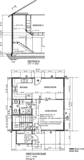
Figure 5.15 A framing plan for the ground-floor platform of the building shown in Figure 5.17.
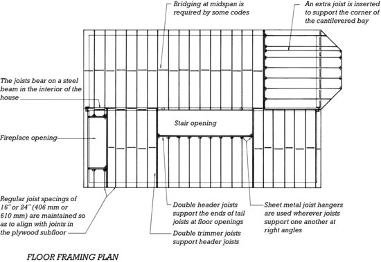
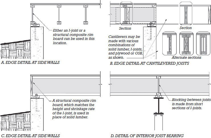
Figure 5.16 Ground-floor framing details for both solid lumber (above) and I-joist framing (below), keyed to the lettered circles in Figure 5.17. Continuous pieces of lumber are drawn with an X inside and intermittent blocking with a single diagonal. In both details B, framing members that cantilever beyond the foundation must either be preservative-treated or the deck construction must be carefully detailed to protect the framing from moisture and decay. The I-joist version shows cantilevered, preservative-treated solid lumber joists overlapped with the interior I-joist framing; several alternative framing strategies are also shown. (For clarity, webs of I-joists seen in elevation are shaded.)
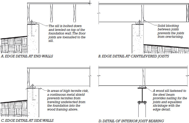
Figure 5.16 (Continued)
Erecting the Frame
The building of the platform frame structure is referred to as rough carpentry. The concept of platform frame construction, outlined in Figure 5.3, is illustrated in more detail in this chapter's sequential isometric diagrams, beginning with Figure 5.17, the first-floor platform. In succeeding illustrations, notice how each floor platform provides a ready work surface for the next step in the construction process. As a result, most of the work is accomplished without the use of ladders or scaffolding, and temporary bracing is needed only to support the walls until the next level of framing is installed and sheathed.
 Figure 5.17 Step three in erecting a typical platform frame building: the ground-floor platform. Compare this drawing with the framing plan in Figure 5.15. Notice how the direction of the joists changes to construct the cantilevered bay on the end of the building. A cantilevered bay on a long side of the building could be framed by merely extending the existing floor joists over the foundation. The bridging shown between joists is discussed later in this chapter. The letters A, B, and C represent portions of the framing detailed in Figure 5.16.
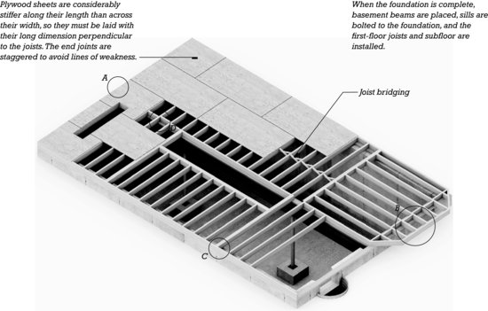
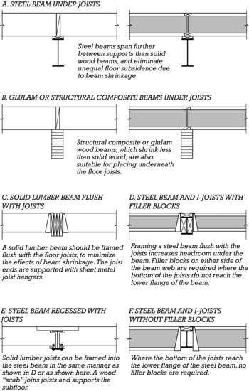
Figure 5.18 Methods of beam support for lumber joists (left column) and I-joists (right column) between foundation walls. Where joists pass over the top of the beam (A, B), beams made of steel, glue-laminated wood, or structural composite lumber should be used. Solid lumber beams should be avoided in this application, as their greater drying shrinkage can cause noticeable subsidence in the floor. Solid lumber beams should be framed flush with the joists (C ) so that their shrinkage occurs in parallel with the joists. Ways to frame joists flush with steel beams are shown in D, E, and F. In D, the bottoms of the joists are above the bottom flange of the beam, and filler blocks are bolted to the web of the beam to restrain the joists from sidesway in the case of a seismic event. Filler blocks also allow the use of face-mounted joist hangers, rather than top-mounted as shown here. In F, the joists are deep enough to be restrained by the bottom flange of the steel beam and no filler blocks are required. In E, a small space must be left over the top of the beam to allow for drying shrinkage in the joists.
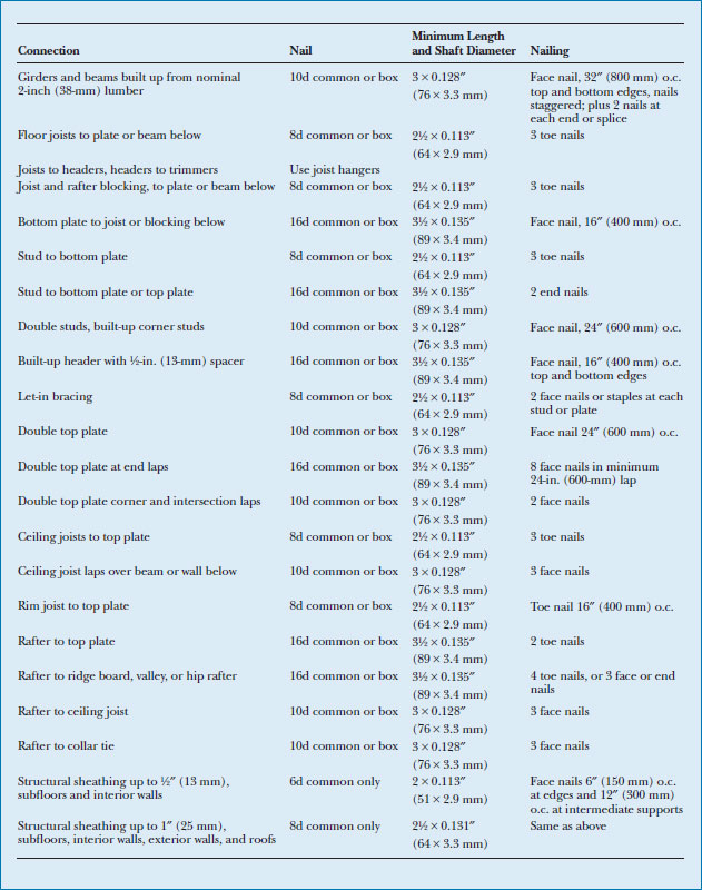
The details of a platform frame building—the sizes, spacing, and connections of its members, and even the size and number of nails for each connection (Figure 5.19)—are constructed according to industry standards and closely regulated by building codes. The most common of these details are shown in the figures accompanying the sequential isometrics, beginning with Figure 5.16.
Figure 5.19 Standard nailing for platform frame construction. These requirements are incorporated into building codes, and experienced framing carpenters know them by heart. For fastening of framing members, either common or box nails are permitted. Structural sheathing must be nailed with common nails only. Where sinkers are used, larger penny sizes than indicated may be needed to meet the minimum length and shaft diameter requirements. Despite the apparent complexity of this list, it is possible to simplify the number of nails types required for rough framing work. For example, all of the above can be accomplished with just a 16d box nail and an 8d common nail. Where this table indicates 10d nails face-nailed into two nominal 2-inch members (3 in. or 76 mm in combined thickness), a 16d nail (3½-in. or 89-mm long) can be used, driven at an angle so that its pointed end does not protrude from the opposite side. A more comprehensive listing of design values and fastening requirements for nails and staples used in structural applications is provided in the industry-standard report ESR-1539. You can download a PDF of this figure at http://www.wiley.com/go/aflblce6ne.
Attaching the Frame to the Foundation
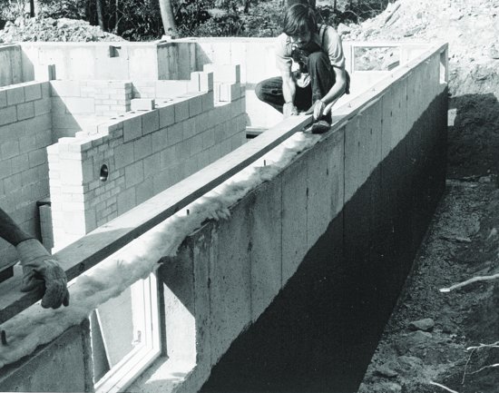
The foundation sill plate (sometimes also called a mudsill), made of preservative-treated wood for resistance to insects and moisture, is attached to the top of the foundation to serve as a base for the wood framing to follow (Figure 5.16, A, B, and C). A single nominal 2-in. (38-mm) sill, as shown in the details here, may be all that is required. In better-quality work or where seismic or wind design forces are high, the sill may be doubled or made from thicker stock for added stiffness and to create a stronger connection between the foundation and the wood frame above. At a minimum, the sill is fastened in place with ½-in. (13-mm) anchor bolts, embedded in the top of the foundation wall and spaced not more than 6 ft (1829 mm) apart. Alternatively, similarly spaced proprietary sheet metal anchor straps may be used instead of bolts.
Because the top of a foundation wall is likely to be somewhat uneven, the sill is shimmed up at low spots with wood shingle wedges or plastic shims to provide a more level base for subsequent framing. (The term “mudsill” is a carryover from times when the sill was set in a bed of cement mortar, or “mud,” to accomplish the same purpose.) A sill seal or sill gasket, made of any of a number of compressible or resilient materials, is inserted between the sill and the foundation to reduce air infiltration through this gap and to restrict moisture wicking up from the foundation into the wood framing (Figure 5.20). Where the risk of termite infestation is high, metal termite shields may be inserted between the foundation wall and the sill. These prevent termites from traveling undetected from cracks in the concrete up into the wood framing. As discussed later in this chapter, where wind and earthquake design forces are high, additional measures may be taken to further strengthen the frame-to-foundation connection.
Figure 5.20 Carpenters apply a preservative-treated wood sill to a sitecast concrete foundation. Compressible glass fiber sill seal has been placed on the top of the concrete wall, and the sill has been drilled with snugly fitting holes at anchor bolt locations. Before each section of sill is bolted tightly, it is leveled as necessary with wood shingle or plastic shims between the concrete and the wood. As the anchor bolts are tightened, the sill seal squeezes down to a negligible thickness. A section of bolted-down sill is visible at the upper right. The basement windows were clamped into reusable steel form inserts and placed in the formwork before the concrete was cast. After the concrete was cast and the formwork was stripped, the steel inserts were removed, leaving a neatly formed concrete frame around each window. A pocket in the top of the wall for a steel beam can be seen at the upper left. (Photo by Edward Allen.)
Floor Framing
Solid lumber floor joists typically range in size from 2 × 6 (38 × 140 mm) for lightly loaded floors and short joist spans, to 2 × 12 (38 × 286 mm) for heavier loads and longer spans. They are most commonly spaced at 16 or 24 in. (406 or 610 mm) o.c. As can be seen in Figure 5.17, this ensures support for the ends of the subflooring at 4-ft (1220-mm) intervals, as occurs when 8-ft (2440-mm)-long panels are laid with their end joints staggered in adjacent rows. For heavy loads or long spans, but where a deeper joist is not practical, a closer joist spacing, such as 12 in. (305 mm) o.c., may also be used.
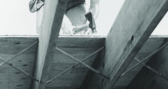
Joists, which rest on their narrow edges, must be restrained from overturning. At a minimum, this is accomplished by end nailing through the rim joists into the joist ends (Figure 5.21). In areas subject to high seismic forces, additional overturning resistance is provided by lines of solid blocking inserted between joists over floor beams, bearing walls, and other intermediate lines of joist support. Additionally, where solid joists exceed 12 in. (286 mm) in depth, bridging (solid blocking, cross-bracing, or strapping) must be inserted at intervals not exceeding 8 feet (2.4 m) (Figure 5.22). In better-quality construction, blocking or bridging may be installed into all floor framing, regardless of seismic or joist depth requirements, to improve stiffness and reduce vibration in the floor system.
Figure 5.21 Installing solid lumber floor joists. Also visible in the face of the rim joist are the toe nails into the sill and the end nails into the floor joists. (Photo by Edward Allen.)
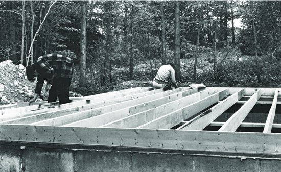
Figure 5.22 Wood crossbridging for I-joists. Bridging installation begins from above, before the subflooring is laid. Fastening of the bottom ends must be completed from below, so, as seen in this photograph, it is frequently deferred until later. Note the printing “TUBING ABOVE AVOID DAMAGE” on the underside of the subflooring panels, indicating hydronic heating tubes installed in upper side of the panels. (Photo by Joseph Iano.)
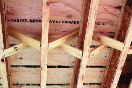
Figure 5.23 Metal crossbridging for solid wood joists. The steel strip is manufactured in a folded V-shape for increased stiffness. One or both ends of the brace may be toothed, to allow installation directly into the joist without the need for nails. (Courtesy of APA–The Engineered Wood Association.)
Where floor openings occur, such as for stairs or chimneys, headers and trimmers are used to frame the opening and carry the floor loads around the opening to supporting walls or beams. For larger openings, these members are doubled to account for the greater loads that they must carry. Where the ends of joists meet a supporting header, nailing alone cannot be relied upon to transfer loads between the members, so sheet metal joist hangers are used. Each hanger provides a secure pocket for the end of the joist and punched holes into which properly sized nails are driven to make the connection. Extra joists may also be inserted into the floor framing anywhere concentrated loads from above are expected, such as underneath bathtubs or loadbearing walls.
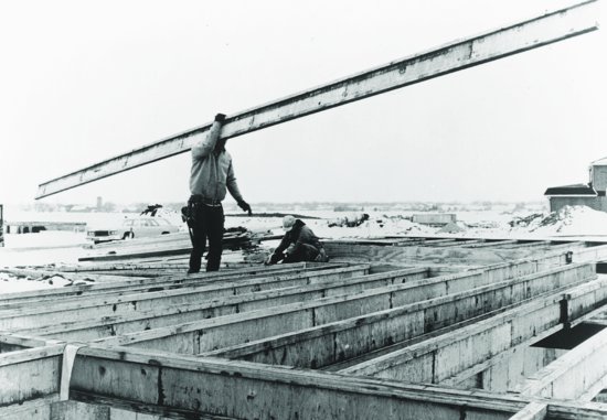
Today, manufactured I-joists are as likely to be used for floor framing as solid lumber (Figure 5.24). Compared to solid wood joists, these components are lighter in weight, can span greater distances, provide greater straightness and uniformity, and reduce drying shrinkage of the floor platform. I-joists can also more easily accommodate piping, ductwork, and wiring within the floor platform, as openings (sized and located so as not to impair the structural capacity of the joist) can be made in the relatively thin web of the I-joist more easily than in solid lumber. Some I-joists are manufactured with preformed web knockouts, ensuring that openings are both easy to make and properly located and sized.
Figure 5.24 A floor platform being framed with manufactured I-joists. The joists in this photograph are made with laminated veneer lumber (LVL) flanges and plywood webs. Note the ease with which one carpenter can lift this relatively long but lightweight member. (Photos provided by Trus Joist MacMillan.)
I-joists range from 9½ to 24 in. (241 to 610 mm) in depth, with flanges from 1¾ to 3½ in. (44 to 90 mm) wide. They are capable of spanning up to approximately 30 ft (9 m). For normal loads and spans, joists are most commonly spaced at 24 in. (610 mm) o.c. However, closer spacings may be used for longer spans, greater floor loads, increased floor stiffness, or where a subfloor panel with a lesser span rating is used.
The relatively thin webs of the I-joist may require special consideration in joist connection details. For example, where a joist hanger is not tall enough to restrain both the top and bottom flanges of the joist, web blocking is inserted on either side of the web to restrain the joist from tipping sideways (Figure 5.25).
Figure 5.25 I-joist web blocking at a sheet metal joist hanger. The blocking is applied to both sides of the web, to restrain the joist from rotating within the hanger. Alternatively, if a taller hanger capable of restraining both the top and bottom flanges of the joist is used, blocking is not required for this purpose. Web blocking may also be used to stiffen the relatively slender web, to prevent it from buckling under heavy loads, such as when a bearing wall rests on the platform directly above. As can be seen in the photograph, web blocking should be cut slightly shorter than the joist web itself, so that if the web compresses slightly under load, the blocking does not pry the top flange apart from the web. (Photo by Joseph Iano.)
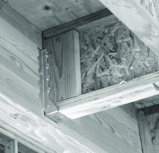
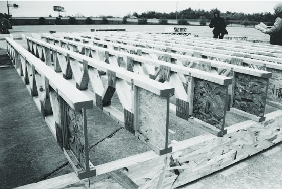
Where the loads applied to I-joists at their ends or at points of intermediate support are high enough to risk buckling or crushing of the joist web, blocking of various types, as shown in Figure 5.47, may also be used. Bridging and blocking, installed to resist joist overturning or stiffen longer spans, are used with I-joists in the same manner as just described for solid lumber joists. Manufactured floor trusses (Figure 5.26), like I-joists, can span farther than solid wood joists, reduce shrinkage in the floor platform, and provide natural openings to accommodate building services.
Figure 5.26 These floor trusses (shown here being set up for a demonstration house in a parking lot) are made of sawn lumber members joined by toothed-plate connectors. The OSB web at each end provides a section of truss that can be sawn by workers to easily adjust the length of the truss as necessary. Trusses are deeper than solid wood joists or I-joists but can span farther. Even though they are deeper than other joist products, they may result in a thinner floor/ceiling assembly, as pipes and even relatively large sections of ductwork can run through the passages within the truss rather than below it. (Photo courtesy of the Wood Truss Council of America.)
In comparison to solid wood joists that provide only 1½ in. (38 mm) of supporting surface for the subfloor above, the top surfaces of I-joists and floor trusses may be as wide as 3½ in. (64 to 89 mm). This allows an opportunity for additional possible economy in the use of these member types. Where solid joists are spaced at 16 in. (406 mm) o.c., it may be possible to space trusses or I-joists at 19.2 in. (488 mm) without having to increase the thickness or strength of the subflooring. This is possible because the wider top surface effectively reduces the span of the subfloor panels between the joists. This small change in joist spacing, which requires one less joist over every 8 ft (2440 mm), results in a 17 percent reduction in joist framing materials and installation labor.
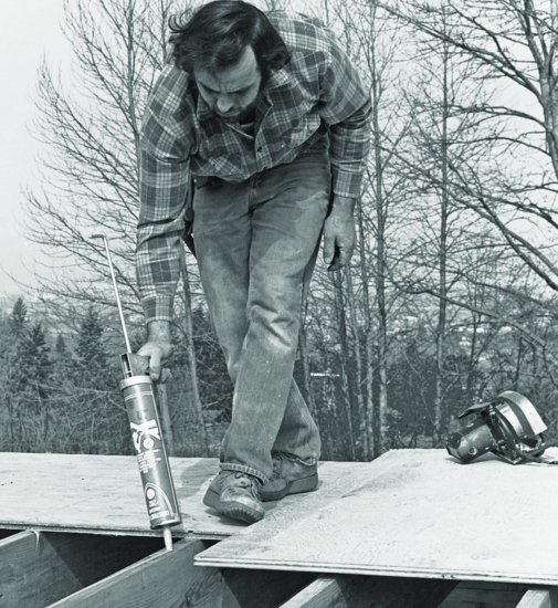
Subflooring is installed after floor framing is complete. The subfloor panels are laid with their longer dimension perpendicular to the framing on which they are supported, as the panels are considerably stiffer in this orientation (Figure 5.27). With plywood subflooring, which typically has different veneer grades on either side, the panel is laid with the better grade facing up. A ⅛-in. (3-mm) gap is maintained around all panel edges, to prevent buckling caused by the expansion of rain-wetted panels. To reduce squeaking in the finished floor and increase floor stiffness, adhesive may be applied to the tops of joists before the panels are laid, and deformed shank nails or self-drilling screws with greater withdrawal resistance than plain common nails may be used for fastening (Figure 5.28).
Figure 5.27 Applying OSB subflooring. Note that the longer dimension of the panel runs perpendicular to the joist framing. (Courtesy of APA–The Engineered Wood Association.)
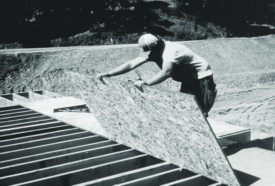
Figure 5.28 For a stiffer, quieter floor, subflooring may be glued to the joists. The adhesive is a thick mastic that is squeezed from a sealant gun on the tops of the joists just before the subflooring is laid in place. (Courtesy of APA–The Engineered Wood Association.)
Wall Framing
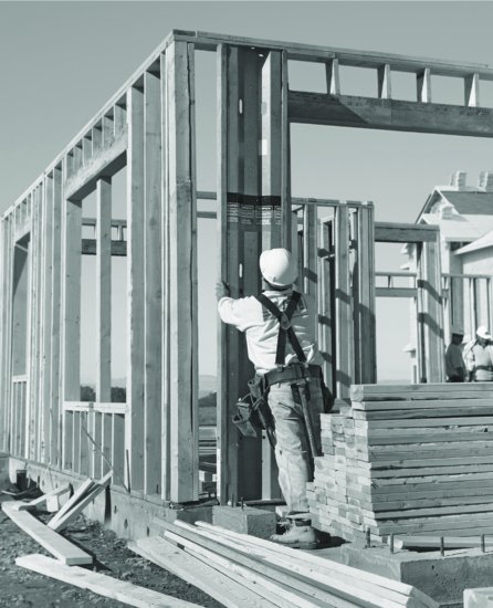
Walls are usually framed with 2 × 4 (38 × 89 mm) or 2 × 6 (38 × 140 mm) members—the deeper 2 × 6 used to support greater loads or provide more space for insulation in the wall. Solid lumber studs are most common. However, structural composite or finger-jointed lumber may also be used. Like floor joists, wall studs are spaced at 16 or 24 inches (406 or 610 mm) to coordinate with the 4-foot (1.2-m) module of exterior sheathing and interior wallboard panels. Studs are nailed in place between top and bottom plates made from the same size lumber as the studs. With loadbearing walls, the top plate is doubled for greater strength and stiffness, to help with the transfer of the loads from above into the studs below. Walls are constructed in sections lying down, using the previously built floor platform as a work surface. When ready, they are tilted up, plumbed (set vertical), and nailed into position, with temporary bracing applied to hold them in position until adjoining framing is completed (Figures 5.29 through 5.36).
Figure 5.29 Typical ground-floor wall framing details, keyed by letter to Figure 5.30.

 Figure 5.30 Step four in erecting a platform frame building: The ground-floor walls are framed. The letters A, C, D, and F indicate portions of the framing that are detailed in Figure 5.29.
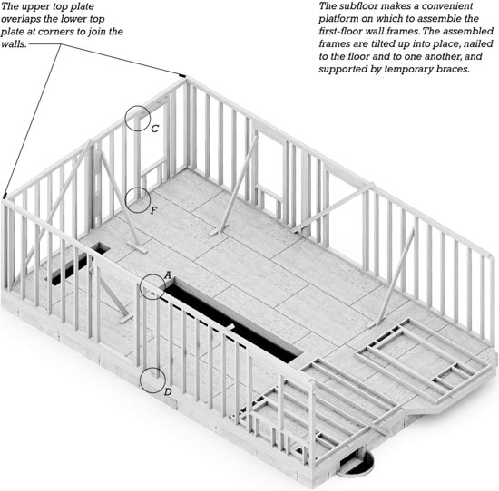
Figure 5.31 Framing details for nonloadbearing interior partitions.
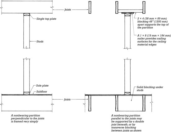
Figure 5.32 Steps in the framing of a typical wall and details at wall intersections and a window opening. In D, the short studs above the header and below the rough sill are called “cripple studs.”
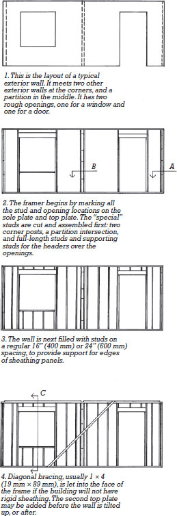
Figure 5.32 (Continued)
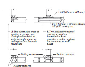
Figure 5.32 (Continued)
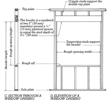
Figure 5.33 The wall frame is constructed while it lies flat on the already completed floor platform. Here, studs for a partition intersection are nailed to a plate, using a pneumatic nail gun. (Photograph courtesy of Senco Products, Inc.)
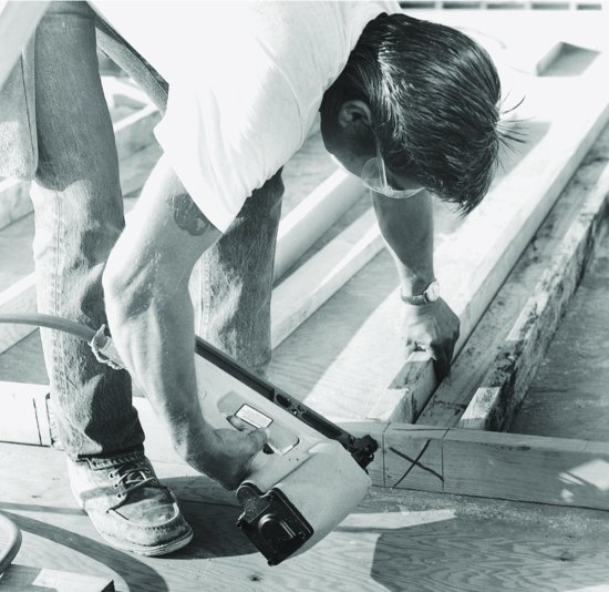
Figure 5.34 Tilting an interior partition into position. The gap in the upper top plate will receive the projecting end of the upper top plate from another partition that intersects at this point. (Courtesy of APA–The Engineered Wood Association.)
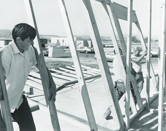
Figure 5.35 Fastening a wall to the floor platform. Horizontal blocking between studs, as seen toward the left in this photo, is installed to provide solid fastening for bathroom hardware, exterior panels, or any number of possible other items to come later. (Photograph courtesy of Senco Products, Inc.)
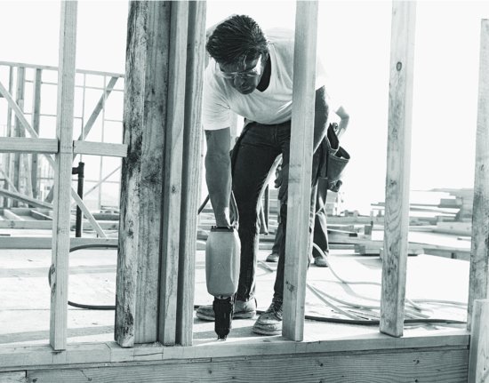
Figure 5.36 Wall framing is held in place by temporary bracing until the floor framing is in place above and wall sheathing is complete, after which the frame becomes self-bracing. The outer walls of this building are framed with 2 × 6 (38 × 140 mm) studs to allow for a greater thickness of thermal insulation, whereas the interior partitions are framed with 2 × 4 (38 × 89 mm) studs. (Photo by Joseph Iano.)
Openings for windows and doors are formed with headers, trimmers, and sills. Headers, spanning across the top of an opening, take the loads from above the opening and carry them to either side. They are made from two members on edge, with material sandwiched between so that their total width is equal to that of the wall. The depth of the header varies according to the work it must perform: shallow for light loads and short spans, and deeper for larger loads and longer spans. Where they are needed, structural composites with greater strength, such as LVLs or PSLs, may be used. Prefabricated headers that include integrated thermal insulation to reduce heat loss through these difficult-to-insulate areas may also be used. At either end, headers rest on shortened studs called trimmer or jack studs, which themselves are nailed to full-height king studs. At the bottom of a window opening, the rough sill is supported on cripple studs (Figure 5.32).
Where walls intersect, nailing surfaces must be provided for supporting the edges of the exterior sheathing and interior wallboard. This requires at least three studs at each intersection, unless special metal clips are used to reduce the number to two (Figure 5.32).
Walls exceeding 10 ft (3 m) in height must have solid blocking inserted at midheight, to limit the volume of the wall cavities and reduce the ease with which fire can spread within the wall. Where long, consistently straight pieces of solid lumber are not readily available for the construction of unusually tall walls, structural composite or finger-jointed stock may be used.
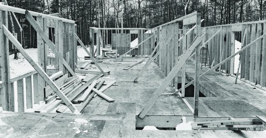
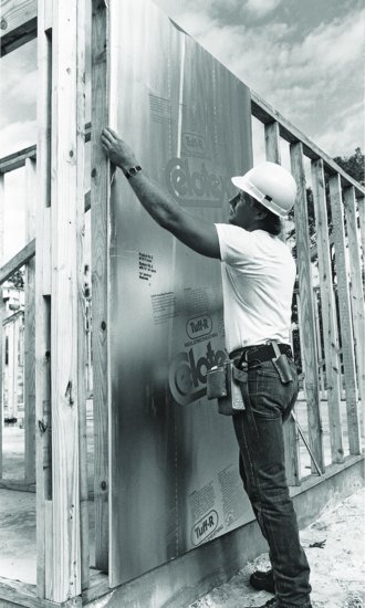
Wall sheathing, most frequently plywood or OSB, provides a nailing surface for exterior cladding materials and stiffens the wall against the lateral forces of wind or earthquake (Figure 5.1). Other sheathing panel types, made from wood or paper fiber, plastic foam, or glass or mineral fiber, are intended principally as thermal insulation and to provide a base for building paper, housewrap, or other weather-resistant coverings. Where walls are sheathed with such nonstructural panels, let-in diagonal bracing can be used to provide lateral force resistance. Let-in bracing may be made of 1 × 4 (19 × 89 mm) wood boards, or light steel members that are recessed into the outer face of the studs of the wall before it is sheathed (Figures 5.32 and 5.37). However, let-in bracing is less effective at resisting lateral forces than structural panel sheathing, and it is not suitable for use where these forces are high.
Figure 5.37 Applying a panel of insulating foam sheathing. Because this type of sheathing is too weak to brace the frame, diagonal bracing is inserted into the outside faces of the studs at the corners of the building. Steel let-in bracing, nailed at each stud, is used in this frame and is visible just to the right of the carpenter's leg. (Courtesy of The Celotex Corporation.)
Lateral Force Resistance and Shear Walls
To a greater or lesser degree, all structures must resist the horizontally acting forces of wind and earthquake. In areas prone to very strong winds or severe earthquakes, as well as for taller wood light frame structures, special attention is given to the design of the platform frame and the detailing of its connections to ensure that it can safely withstand the effects of these lateral forces (Figure 5.38).
Figure 5.38 Lateral forces acting on a building can cause sliding (top), overturning (middle), or wracking (bottom). An additional consideration, failure between structural parts, is discussed in the accompanying text.
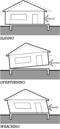
Lateral forces acting on a building can cause the structure to slide off its foundation, overturn, wrack, or suffer failures among its parts. Sliding at the top of the foundation is resisted by the anchor bolts and foundation sill plate, as described earlier in this chapter. Where the forces are high, this connection can be strengthened with thicker plates made of stronger lumber, and anchor bolts that are larger in diameter, more closely spaced, and fastened with larger washers.
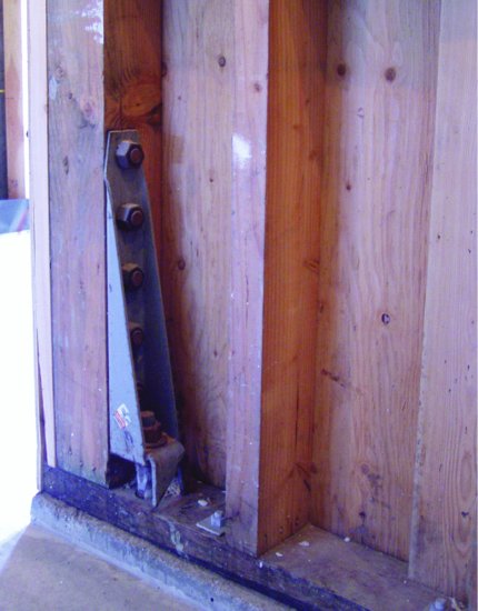
To resist overturning, hold-downs are installed to prevent the structure from lifting off the foundation (as their name suggests). These devices may also be used higher up in the structure to prevent the upper stories or roof from separating from the portions of the structure below (Figures 5.39, 5.40, and 5.41).
Figure 5.39 Strap tie hold-downs are made of galvanized steel straps with hooked or deformed ends cast into the concrete foundation wall (left). After the wall is framed, the exposed length of strap may be nailed directly to framing or, as seen here, nailed through the sheathing into the studs or posts behind (right). The number, size, and spacing of nails used to fasten the strap depend on the magnitude of the loads that must be resisted and the capacity of the wood member to hold nails without splitting. In the left image, anchor bolts cast into the top of the foundation wall that will be used to secure the sill plate in place are also visible. (Photos by Joseph Iano.)
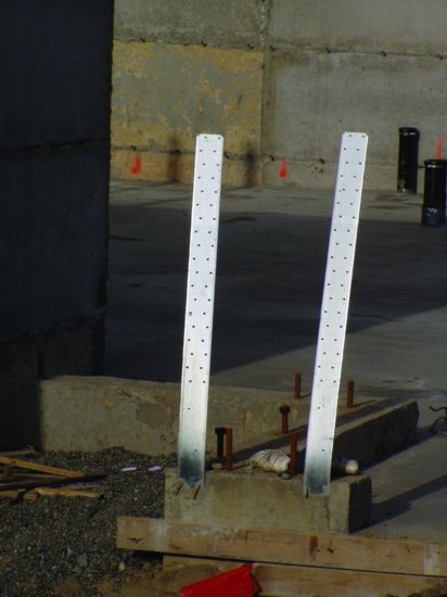
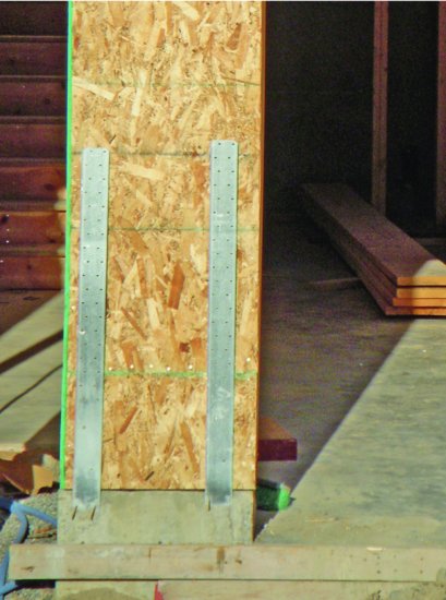
Figure 5.40 Hold-downs made from threaded rod and steel plate anchors can resist much greater forces than strap tie hold-downs. They may be used at each floor level to securely tie the building frame through its full height to the foundation. For the type shown here, the nuts at the ends of the threaded rods may require retightening after the first heating season to compensate for wood shrinkage, which can mean that access holes must be provided through the interior wall surfaces. Other models are made self-adjusting with the use of spring-loaded, tapered shims or other compensation mechanisms.

Figure 5.41 A heavy-duty seismic hold-down similar to that illustrated in the previous figure. The anchor rod with one end cast into the concrete foundation wall protrudes through the preservative-treated wood sill where its threaded end is bolted to the anchor. The anchor in turn is bolted to a 4 × 4 (89 × 89 mm) post with five bolts of substantial diameter. A conventional foundation anchor bolt with an oversized square washer is also partially visible to the right of the hold-down. Also note the thicker-than-normal, 3-inch nominal (64-mm) sill plate, a common feature in wood light framing designed for high seismic forces. (Photo by Joseph Iano.)
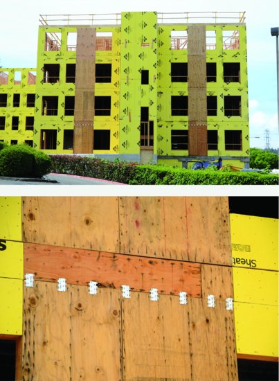
A wall without sheathing or bracing has no useful resistance to wracking. Because the nailed connections between studs and plates are flexible, the wall can easily deform. In areas of high wind force or earthquake risk, plywood or OSB sheathing panels tightly nailed to the framing create shear walls that provide the necessary rigidity. As lateral force design values increase, shear walls are made stronger by lengthening the wall, using thicker structural panels, adding a second panel to the opposite side of the wall, increasing the size of nails used to attach the panels to the framing, and spacing nails more closely, especially around panel edges. Shear walls frequently also require extra studs or thicker posts at their ends, to prevent localized crushing or failure where forces tend to concentrate (Figure 5.41).
Both interior and exterior walls can act as shear walls. Separate sections of wall must be arranged perpendicularly so that the structure as a whole can resist forces acting from different directions. Shear walls must also be distributed in plan so as to ensure a reasonably balanced overall response to such forces.
Figure 5.42 Above, shear walls for a multistory, wood light frame structure. The darker hue of the plywood sheathing used at the two shear walls distinguishes them from the surrounding framing covered with gypsum panel sheathing. Below, a close-up of the shear wall at the second-floor platform level. The metal clips increase the shear force transfer capacity between the top of the first-floor wall and the second-floor platform. The panel nailing pattern can be observed by the fastener weathering stains. Fasteners are more closely spaced at panel edges. The multiple rows of fasteners at the extreme left and right of the shear wall are an indication of the thicker framing members used at these locations. (Photos by Joseph Iano.)
Openings in shear walls, such as for doors and windows, significantly reduce their lateral force resistance. Where such openings occur, they are reinforced with blocking and strapping. Where openings take up too large a percentage of the wall area and conventional construction methods cannot provide the necessary resistance, stronger and stiffer welded steel frames or factory-fabricated shear panels made of wood or steel components may be used (Figure 5.43).
Figure 5.43 Prefabricated shear panels are especially useful where large openings in walls leave little solid area for shear wall construction, such as in garage walls. They may be made of all wood components or, where even greater strength is required, of wood and metal, as shown here. The corrugated galvanized steel in this panel is more than ⅛ inch (3.5 mm) thick, and the panel's capacity to resist lateral forces is several times greater than that of comparable all-wood prefabricated panels. The bottom of the panel will be anchored with bolts embedded 21 inches (533 mm) or more into the concrete foundation, and the sides and top will be screw-fastened to the surrounding wood framing. Holes in the panel can accommodate wiring runs within the wall. (Courtesy of Simpson Strong-Tie Company Inc.)
In the International Building Code, the term “shear wall” is reserved for a lateral-force-resisting wall designed by a professional engineer, for use in a single building. Where the design conditions are not too severe, the code also provides for more general purpose, preengineered, prescriptive wall designs. These so-called braced walls or braced panels are designed and built according to the same principles as shear walls, the difference being that no professional analysis is required. Where design forces are low, sheathing panels made from fiberboard, particle board, or even gypsum wallboard, rather than plywood or OSB, may provide adequate rigidity.
With the components necessary to resist sliding, overturning, and wracking incorporated into the building structure, it still remains necessary to ensure that the various building parts are adequately interconnected. Collectors (also called drag struts or drag ties) are components that transfer lateral forces from larger areas, such as floors or roofs, to the parts of the structure designed to resist these forces, such as the shear walls. For example, wall top plates typically collect lateral forces that accumulate in the floor platform above and carry these forces to the top of the nearest shear wall. Strategically located and properly fastened joists, rafters, other framing members, and (where necessary) metal strapping or solid wood blocking may also perform in this way (Figure 5.44). Collectively, these components ensure continuous load paths so that forces acting within the various parts of the structure will be carried reliably and securely to the building foundation and surrounding soil.
Figure 5.44 In addition to supporting gravity loads over the garage opening, this glulam beam acts as a collector of lateral forces in the deck framing that it supports. These forces are carried either to the narrow section of solid wall framing on the right, or via the metal strap and adjacent garage opening beam, to additional shear wall framing beyond the edge of this photograph. (Photo by Joseph Iano.)
Upper-Level Floor and Wall Framing
After the first-floor platform and wall framing are complete, the process and details of floor framing followed by wall framing may continue for each additional level of the structure, as shown in Figures 5.45 through 5.50.
 Figure 5.45 Step five in erecting a two-story platform frame building: building the upper-floor platform. The letters A, B, and C indicate portions of the framing that are detailed in Figures 5.46 and 5.47.
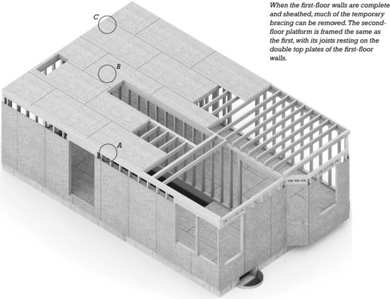
Figure 5.46 Details of the second-floor platform, keyed to the letters in Figure 5.45. The extra piece of lumber attached to the top plate in C provides a nailing surface for the edge of the finish ceiling material, which is usually either gypsum board or veneer plaster base.

Figure 5.47 I-joist framing details analogous to those for solid lumber shown in Figure 5.46. For clarity, the web of the I-joist is rendered light blue and blocking with a darker shade. The web stiffener shown in A is cut slightly shorter than the height of the web of the joist, and is installed so that a small space remains between the top of the blocking and the underside of the top flange. This prevents the blocking from prying the flanges apart if the I-joist itself shrinks or is compressed slightly (see also Figure 5.25). The blocking in B-1 functions identically to the solid blocking shown in Figure 5.46B. A squash block is shown in B-2. This is a short section of 2-in. (38-mm) framing, installed vertically like a very short stud on either side of the I-joist. Squash blocks are used under points of concentrated load, such as under loadbearing posts or studs on either side of a large opening in a wall above. They are cut slightly longer than the full height of the joist to ensure that the loads are transmitted through the blocks and not the joist.
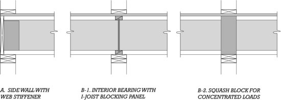
Figure 5.48 Installing upper-floor plywood combination subflooring/underlayment. The plywood panel grade is C–C Plugged. Its top (plugged) face has all surface voids filled and is lightly sanded, making it sufficiently smooth to allow carpeting to be installed directly over the subfloor without additional underlayment. The long edges of the panels have interlocking tongue-and-groove joints to prevent deflection of panel edges under heavy loads. (Courtesy of APA–The Engineered Wood Association.)
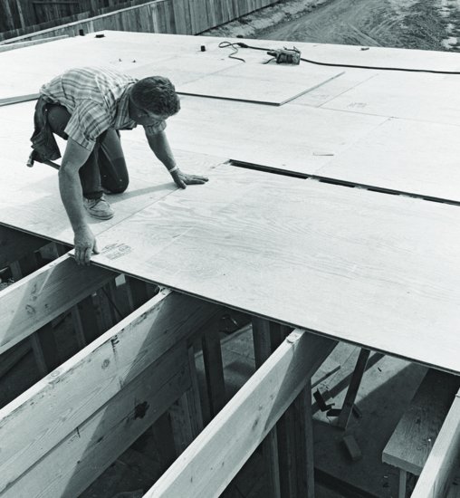
 Figure 5.49 Step six: The second-story walls are framed. The circle labeled A corresponds to the top of stair detail shown in Figure 5.50.
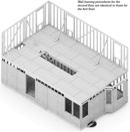
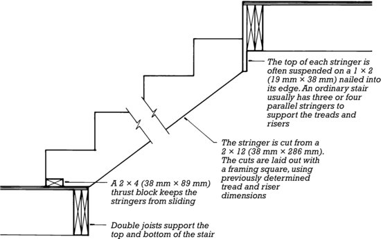
Figure 5.50 Interior stairways are usually framed as soon as the upper-floor platform is completed. This gives the carpenters easy up-and-down access during the remainder of the work. Temporary treads of joist scrap or plywood are nailed to the stringers. These will be replaced by finish treads after the wear and tear of construction are finished.
Roof Framing
The generic roof shapes for wood light frame buildings are shown in Figure 5.51. Simple shapes are combined into more complex arrangements suitable for covering any building plan shape and volume.
Figure 5.51 Basic roof shapes for wood light frame buildings.
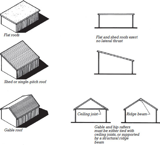
Figure 5.51 (Continued)
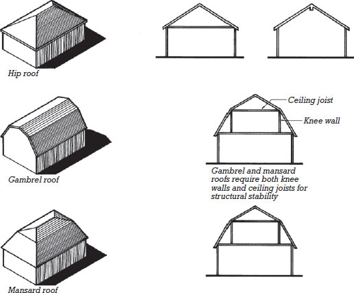
For structural stability, rafters in gable and hip roofs must be securely tied together at the top of the supporting walls by well-nailed ceiling joists to make what is, in effect, a series of triangular trusses. If the designer wishes to eliminate the ceiling joists and expose the sloping underside of the roof as the finished ceiling surface, a ridge beam or bearing wall must be inserted at the ridge or a system of exposed horizontal ties must be used in place of the joists. Sometimes a designer wishes to raise the ceiling joists or exposed rafter ties to a higher elevation than the tops of the wall plates. This greatly increases the stresses in the rafters and should be done only within the prescriptive limits of the building code or after consultation with a structural engineer. As with floor framing, ceiling joists and rafters must be protected against overturning. Requirements vary with the span, depth, and support conditions of the members and may include end nailing, blocking, bridging, or strapping, similar to those shown earlier in this chapter for floor joist framing.
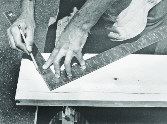
Although a college graduate architect or engineer would find it difficult to use the necessary trigonometry to lay out the cuts for a rafter in a sloping roof, a skilled carpenter, without resorting to mathematics, has little problem making the layout when the pitch (slope) is specified as a ratio of rise (vertical dimension) to run (horizontal dimension). In the United States, pitch is usually given as inches of rise per foot (12 inches) of run. The carpenter uses these two figures on the two edges of a framing square to lay out the rafter, as shown in Figure 5.53. The actual length of the rafter is never figured, nor does it have to be, because all the measurements are made as horizontal and vertical distances with the aid of the square. Today, many carpenters prefer to do rafter layout with the aid of tables that give actual rafter lengths for various pitches and horizontal distances; these tables are stamped on the framing square itself or printed in pocket-size booklets. Also available are hand-held calculators that are specially programmed to find dimensions of rafters.
Figure 5.52 A roof framing plan for the building illustrated in Figure 5.54. The dormer and chimney openings are framed with doubled header and trimmer rafters. The dormer is then built as a separate structure that is nailed to the slope of the main roof.
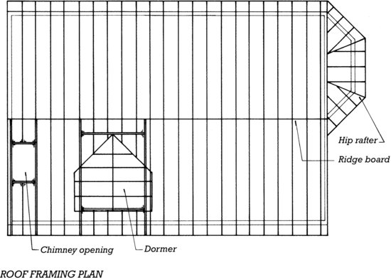
Figure 5.53 Roof framing details and procedures: The lettered details are keyed to Figure 5.54. The remainder of the page shows how a framing square is used to lay out a pattern rafter, reading from the first step at the lower end of the rafter to the last step at the top. The rafter detailed here is a common rafter, as distinguished from hip, valley, and jack rafters as shown in Figure 5.55. You can download a PDF of this figure at http://www.wiley.com/go/aflblce6ne.
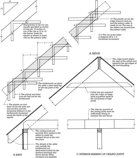
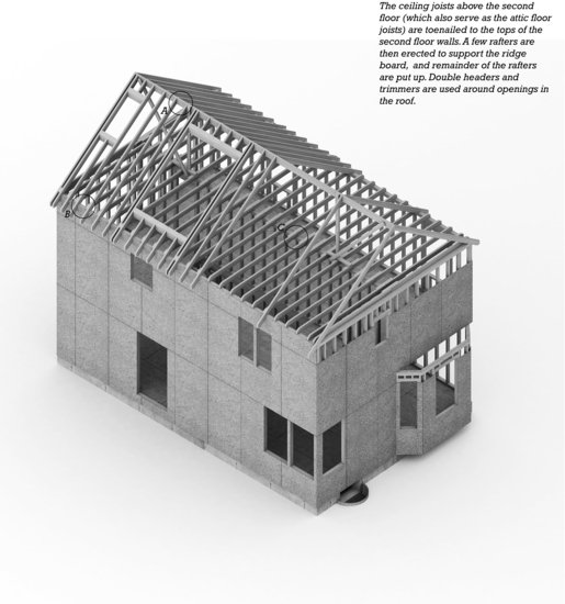
 Figure 5.54 Step seven: framing the attic floor and roof. The outer ends of attic floor joists are not usually headed off, but instead are face nailed to the rafter pairs that overlap them.
Hips and valleys introduce another level of trigonometric complexity in rafter layout, but the experienced carpenter has little difficulty even here: Again, he or she can use published tables for hip rafters and valley rafters or do the layout the traditional way, as illustrated in Figure 5.55. The head carpenter lays out only one rafter of each type by these procedures. This then becomes the pattern rafter from which other rafters can be traced and cut (Figure 5.58).
Figure 5.55 Framing for a hip roof. The difficult geometric problem of laying out the diagonal hip rafter is solved easily by using the framing square in the manner shown. Toward the bottom of the rafter shown in the lower part of this figure is a birdsmouth cut, an angled notch in the rafter that allows the rafter to seat securely on the top plate of the wall. You can download a PDF of this figure at http://www.wiley.com/go/aflblce6ne.
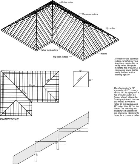
Figure 5.56 Framing for an overhanging rake.
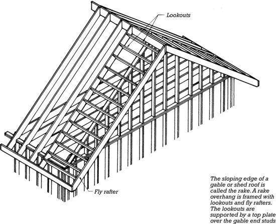
Figure 5.57 A framing square being used to mark rafter cuts. The run of the roof, 12 inches, is aligned with the edge of the rafter on the blade (the wider leg) of a square, and the rise, 7 inches in this case, is aligned on the tongue (the narrower leg) of the square. A pencil line along the tongue will be perfectly vertical (a plumb cut) when the rafter is installed in the roof, and one along the blade will be horizontal (a level cut). True horizontal and vertical distances can be measured on the blade and tongue, respectively. The layout of these types of cuts can also be seen in Figures 5.53 and 5.55. (Photo by Edward Allen.)
In areas subject to hurricanes, special care must be taken to ensure that rafters are securely attached to their supporting walls with sheet metal rafter anchors such as the one shown in Figure 3.50. The type, size, and spacing of the nails that attach the roof sheathing to the rafters are also closely controlled. The intent of both of these measures is to reduce the likelihood that the roof will be blown off in high winds.
The balloon frame is closely connected with the level of industrialization which had been reached in America [in the early 19th century]. Its invention practically converted building in wood from a complicated craft, practiced by skilled labor, into an industry. . . . This simple and efficient construction is thoroughly adapted to the requirements of contemporary architects. . . . [E]legance and lightness [are] innate qualities of the balloon-frame skeleton.
—Sigfried Giedion, Space, Time and Architecture: The Growth of a New Tradition, 1967
Figure 5.58 Tracing a pattern rafter to mark cuts for the rest of the rafters. The corner of the building behind the carpenters has let-in corner braces on both floors, and most of the rafters are already installed. (Courtesy of Southern Forest Products Association.)
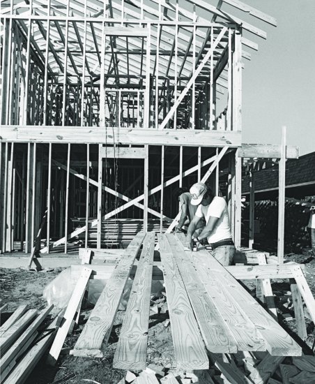
Figure 5.59 I-joists may be used as rafter material instead of solid lumber. (Photos provided by Trus Joist MacMillan.)
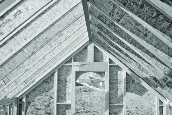
Figure 5.60 Applying plywood roof sheathing to a half-hipped roof. Blocking between rafters at the wall line (far left in the photo) has been drilled with large holes for attic ventilation. The line of horizontal blocking between studs is to support the edges of plywood siding panels applied in a horizontal orientation. (Courtesy of APA–The Engineered Wood Association.)
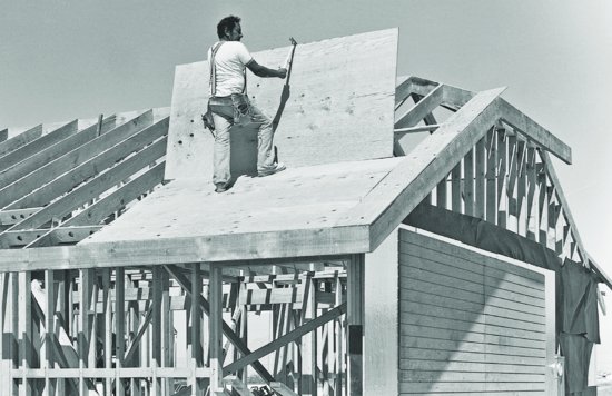
Figure 5.61 Fastening roof sheathing with a pneumatic nail gun. (Photograph courtesy of Senco Products, Inc.)
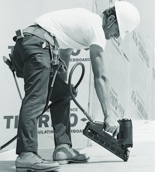
 Figure 5.62 Step eight: The sheathed frame is completed.
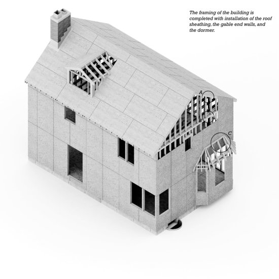
Figure 5.63 A wood light frame structure fully sheathed with plywood structural panels. Installation of wood trim around the edges of the roof has also begun. (Photo by Joseph Iano.)
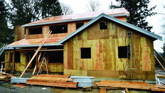
Figure 5.64 Comparison of walls framed with conventional and advanced techniques. Wall A is framed as explained in Figure 5.32. Studs are spaced at 16 inches (406 mm) o.c., the layout of the wall and its openings is not coordinated with the framing module, and standard details are used for corners, openings, and other features. In wall B, studs are spaced at 24 inches (610 mm) o.c., the length of the wall and the location and size of its openings have been coordinated to the greatest extent possible with the 24-inch module, and redundant framing members have been eliminated. Note that with the single top plate, floor joists or roof rafters (shown dashed in these figures) bearing on wall B must fall directly over studs below. The total length of framing lumber used in wall B is half that required for wall A. Though only a foot and a half shorter in length, wall B also can be sheathed with five standard-sized sheathing panels, whereas wall A requires six. Even if wall A is constructed of 2 × 4 studs and wall B is constructed of 2 × 6 studs, the overall savings in materials and reduction in waste in wall B are substantial.
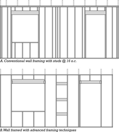
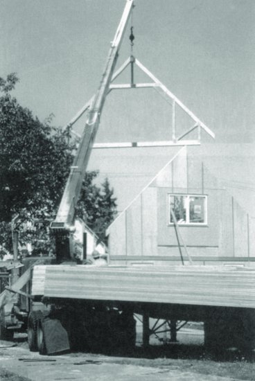
Figure 5.65 Roof trusses are typically lifted to the roof by a boom mounted on the delivery truck. This is one of a series of identical attic trusses that will frame a habitable space under the roof. (Photo by Rob Thallon.)
VARIATIONS ON WOOD LIGHT FRAME CONSTRUCTION
Framing for Increased Thermal Efficiency
The 2 × 4 (38 × 89 mm) has been the standard-size wall stud since light framing was invented. In recent years, however, pressures for greater conservation of fuel for heating and cooling have led to energy code requirements for more thermal insulation than can be inserted in the cavities of a wall framed with members only 3½ inches (89 mm) deep. One solution is to frame walls with 2 × 6 (38 × 140 mm) studs, usually at a spacing of 24 inches (610 mm), creating an insulation cavity 5½ inches (140 mm) deep. Alternatively, 2 × 4-framed walls may be covered either inside or out with insulating plastic foam sheathing, thus reaching an insulation value about the same as that of a conventionally insulated 2 × 6-framed wall. For even greater insulation performance, 2 × 6 studs and insulating sheathing may be used in tandem. (Increasing the stud spacing or adding insulation to one side or the other of the studs also helps to reduce energy losses due to thermal bridging at the studs.) In very cold climates, even more heavily insulated wall assemblies that can achieve greater energy savings may be constructed. Some of these construction methods are illustrated in Figures 7.17 through 7.21.
Framing for Optimal Lumber Usage
Using advanced framing techniques (also called optimum value engineering), redundant or structurally superfluous wood members are minimized, thereby reducing the amount of lumber needed to construct the frame and, once the frame is insulated, increasing its thermal efficiency (Figure 5.64). A variety of techniques may be used, including:
- Spacing framing members at 24 inches (610 mm) rather than 16 inches (406 mm) o.c.: Wider spacing of framing members reduces the amount of lumber required. In exterior walls, thermal efficiency is improved in comparison to walls framed with more closely spaced members by the reduction in thermal bridging that occurs at the studs.
- Designing to a 24-inch (610-mm) module: When the outside dimensions of a framed structure conform to a 24-inch module, sheathing panel waste is minimized. Planning rough opening sizes and locations in floors, walls, and roofs to conform, where possible, to this module can reduce waste even further. Designing to modular dimensions also reduces wastage of interior wallboard.
- Using single top plates in all walls, both bearing and nonbearing: In the case of bearing walls, this requires floor or roof framing members to align directly over studs in the walls that support them.
- Minimizing other unneeded framing members: Avoid headers over openings in nonbearing walls, as they are not needed; in bearing walls, use headers only as deep as required for the loads and span. Where corner studs serve only to provide nailing surfaces or support for wallboard, use other, less wasteful blocking techniques or metal clips designed for this purpose instead. Replace jack studs supporting headers at window and door openings with metal hangers; eliminate unneeded cripple studs under rough sills. All of these techniques save lumber and, in exterior walls, increase energy efficiency by reducing thermal bridging through solid framing.
- Eliminating unneeded plywood and OSB wall sheathing: Where let-in bracing is structurally adequate for lateral force resistance, eliminate structural panel wall sheathing entirely and cover walls with insulating sheathing for better thermal efficiency. Where structural panels are required, use the minimum number of panels necessary.
Advanced framing techniques rely on unconventional framing methods and greatly reduce redundancy in the building frame. For these reasons, they should not be used without guidance from a structural engineer or other qualified design professional, and special review and approval from local building authorities may be required. Nevertheless, where these techniques are used, significant benefits can be realized. According to the National Association of Home Builders Partnership for Advancing Technology in Housing, advanced framing techniques can reduce the amount of lumber used in a wood light frame structure by up to 19 percent and improve the energy efficiency of the insulated structure by as much as 30 percent.
Prefabricated Framing Assemblies
Roof trusses, and to a lesser extent floor trusses, are used in platform frame buildings because of their speed of erection, economy of material usage, and long spans. Though some floor trusses are light enough to be lifted and installed by two carpenters, most truss assemblies are erected with the aid of a small crane that often is attached to the truck on which the trusses are delivered (Figure 5.65). Roof trusses are particularly slender in proportion, usually only 1½ inches (38 mm) thick and capable of spanning 24 to 32 feet (7.5 to 10 m). They must be temporarily braced during construction to prevent buckling or the domino-like collapse of all the trusses until they are adequately secured permanently by the application of internal bracing, roof sheathing panels, and interior finishes (Figure 5.66). Panelized walls—framed and sheathed sections of wall assembled in the factory and delivered to the construction site ready to be erected—are used mostly by larger, high-volume builders who construct hundreds or thousands of houses per year.
WOOD LIGHT FRAME CONSTRUCTION AND THE BUILDING CODES
As shown in the table in Figure 1.3, the International Building Code allows buildings of almost every occupancy group to be constructed with wood platform framing, classified as Type V construction, but with relatively strict restrictions on height and floor area. For example, an unsprinklered, commercial office building, Occupancy Group B, built of Type V-B (unprotected) construction may be two stories in height and 9000 square feet (835 m2) in area per floor. In comparison, if built of Type IV heavy timber construction, the same building may be five stories tall and up to 36,000 square feet (3345 m2) per floor and, if built of more fire-resistive noncombustible construction types, even larger. (Recall also that allowable floor areas in this table can in many circumstances be increased by installing an automatic fire suppression sprinkler system in the building, as outlined in Chapter 1 of this book.)
Building size may also be increased by subdividing a structure with fire walls, an approach commonly used in the construction of attached dwellings and row townhouses. A fire wall separates a single structure into separate portions, each of which is treated by the building code as a independent structure and may have a floor area as large as that normally permitted for an entire building. The required fire resistance of the fire wall is given in a separate table in the code, reproduced in this book as Figure 1.7. Additionally, the fire wall must extend from the foundation through the roof and must be constructed so that it remains standing even if the construction on either side burns completely away. The traditional fire wall is made of brick or concrete masonry, but lighter, less expensive systems using metal framing and gypsum board may also be used (Figures 5.67 and 5.68).
Figure 5.66 A roof framed with prefabricated trusses. Approximately midway up the upper chords of the trusses, temporary strapping ties the trusses to one another for bracing. Other diagonal bracing, not visible in this photograph, ties the trusses to floor or ceiling framing to prevent the entire row from collectively tipping sideways. (Photo by Joseph Iano.)
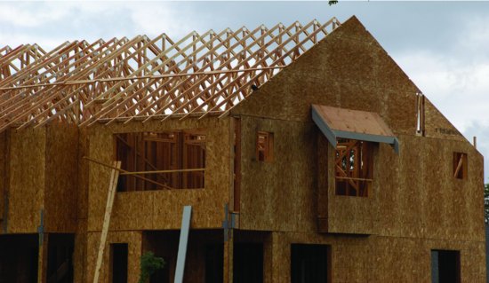
Figure 5.67 This proprietary fire wall consists of light gauge metal framing, noncombustible insulation, and gypsum board. The metal framing is attached to the wood structure on either side with special clips (not shown here) that break off if the wood structure burns through and collapses, leaving the wall supported by the undamaged clips on the adjacent building. (Photographs of Area Separation Wall supplied by Gold Bond Building Products, Charlotte, NC.)
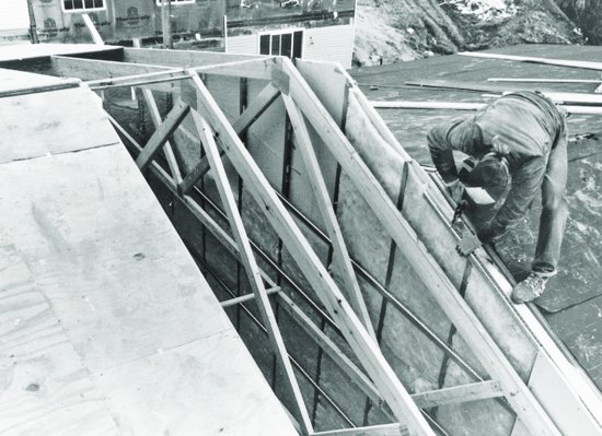
Figure 5.68 This townhouse has collapsed completely as the result of an intense fire, but the houses on either side, protected by fire walls of the type illustrated in Figure 5.67, are essentially undamaged. (Photographs of Area Separation Wall supplied by Gold Bond Building Products, Charlotte, NC.)
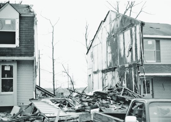
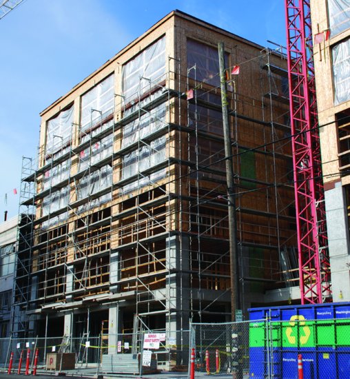
Though platform frame construction is the least fire-resistive of all construction types, building code limits placed on it are sufficiently flexible to allow its use for a diverse range of building uses (Figure 5.69). Furthermore, its economies are such that most building owners will choose platform frame construction over more fire-resistant construction types if given the opportunity. And, despite their vulnerability to fire, the comprehensive life-safety requirements of modern building codes ensure that buildings of wood light frame construction are safe places for their occupants. A study published by the Canadian Wood Council of residential fire deaths in Canada showed that the rate of fire deaths in Type VA dwellings is about the same as the death rate in dwellings made of noncombustible types of construction.
Figure 5.69 This mixed-use urban building is being constructed of cast-in-place concrete up to the second-floor level and of wood light framing above. The building code permits such podium structures to be larger in size than those constructed of wood exclusively. (Photo by Joseph Iano.)
UNIQUENESS OF WOOD LIGHT FRAME CONSTRUCTION
Wood light framing is popular because it is a flexible and economical way of constructing buildings (Figures 5.70 through 5.74). Its flexibility stems from the ease with which carpenters using ordinary tools can create buildings of astonishing variety and complexity. Its economy can be attributed in part to the relatively unprocessed nature of the materials from which it is made, and in part to mass-market competition among suppliers of components and materials and local competition among small builders.
Figure 5.70 The W. G. Low house, built in Bristol, Rhode Island, in 1887 to the design of architects McKim, Mead, and White, illustrates both the essential simplicity of wood light framing and the complexity of which it is capable. (Photo Wayne Andrews.)
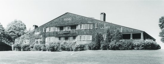
Figure 5.71 In the late 19th century, the sticklike qualities of wood light framing often found expression in the exterior ornamentation of houses. (Photo by Edward Allen.)
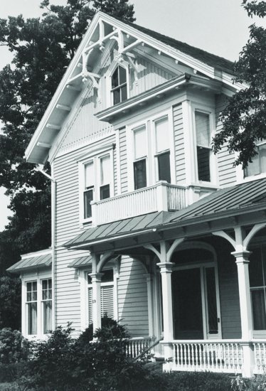
Figure 5.72 Light wood frame construction is used to build the vast majority of housing in North America. It remains to this day the most affordable and versatile construction system for buildings of this type. (Project: New Holly Phase I, by Weinstein A|U Architects & Planners. Photo by Joseph Iano.)
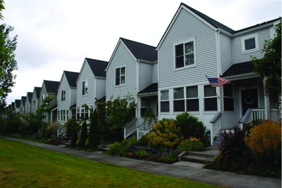
Figure 5.73 In this contemporary New England cottage, designer Dennis Wedlick has exploited the sculptural possibilities of platform framing. (Photo: © Michael Moran.)
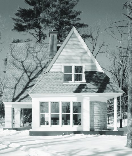
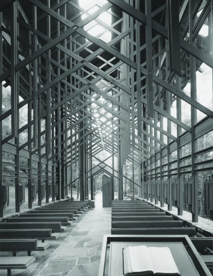
Figure 5.74 The Thorncrown Chapel in Eureka Springs, Arkansas, designed by Fay Jones and Associates, Architects, combines large areas of glass with special framing details to create a richly inspiring space. To avoid damage to the sylvan site, all materials were carried in by hand rather than on trucks. Thus, all framing was done with nominal 2-inch (38-mm) lumber rather than heavy timbers. (Photo by Christopher Lark. Courtesy of American Wood Council.)
Platform framing is the one truly complete and open system of construction that we have. It incorporates structure, enclosure, thermal insulation, mechanical installations, and finishes into a single constructional concept. Thousands of products are made to fit it: competing brands of windows and doors; interior and exterior finish materials; electrical, plumbing, and heating products. For better or worse, it can be dressed up to look like a building of wood or of masonry in any architectural style from any era of history. Architects have failed to exhaust its formal possibilities, and engineers have failed to invent a new environmental control system that it cannot assimilate. Wood light frame construction can be used to construct the cheapest and most mundane buildings. Yet, one can look to the best examples of the Carpenter Gothic, Queen Anne, and Shingle-style buildings of the 19th century, or the Bay Region and Modern styles of more recent times, to realize that wood light framing also gives the designer the freedom to make a finely crafted building that nurtures life and elevates the spirit.
KEY TERMS
optimum value engineering
REVIEW QUESTIONS
1. Draw a series of very simple section drawings to illustrate the procedure for erecting a platform frame building, starting with the foundation and continuing with the ground floor, the ground-floor walls; the second floor, the second-floor walls; and the roof. Do not show details of connections, but simply represent each plane of framing in your section drawing.
2. Draw from memory the standard detail sections for a two-story platform frame dwelling. Hint: The easiest way to draw a detail section is to draw the pieces in the order in which they are put in place during construction. If your simple drawings from Question 1 are correct, and if you follow this procedure, you will not find this question too difficult.
3. What are the differences between balloon framing and platform framing? What are the advantages and disadvantages of each? Why has platform framing become the method of choice?
4. Why is less fireblocking required in platform framing in comparison to balloon framing?
5. Why is a steel beam or glue-laminated wood beam preferred to a solid wood beam for supporting floor joists at the foundation level?
6. How is a platform frame building braced against wind and earthquake forces?
7. Light framing of wood is highly combustible. In what different ways does a typical building code take this fact into account?
EXERCISES
1. Visit a building site where a wood platform frame is being constructed. Compare the details that you see on the site with the ones shown in this chapter. Ask the carpenters about the procedures you see them using. When their details differ from the ones illustrated, make up your own mind about which is better and why.
2. Develop floor framing and roof framing plans for a building you are designing. Estimate the approximate sizes of the joists and rafters using the rules of thumb provided in this chapter.
3. Make thumbnail sketches of 20 or more different ways of covering an L-shaped building with combinations of sloping roofs. Start with the simple ones (a single shed, two intersecting sheds, two intersecting gables) and work up to the more elaborate ones. Note how the varying roof heights of some schemes could provide room for a partial second-story loft or for high spaces with clerestory windows. How many ways do you think there are of covering an L-shaped building with sloping roofs? Look around as you travel through areas with wood frame buildings, especially older areas, and see how many ways designers and framers have roofed simple buildings in the past. Build up a collection of sketches of ingenious combinations of sloping roof forms.
4. Build a scale model of a platform frame from basswood or pine, reproducing accurately all its details, as a means of becoming thoroughly familiar with them. Better yet, build a small frame building for someone at full scale (perhaps a toolshed, playhouse, or garage).
SELECTED REFERENCES
Allen, Edward, and Rob Thallon. Fundamentals of Residential Construction. Hoboken, NJ, John Wiley & Sons, Inc., 2011.
This book expands upon the chapters on residential-scale construction in the book you are now reading, giving full details of every aspect, including plumbing, mechanical and electrical systems, and landscaping.
American Forest & Paper Association. Details for Conventional Wood Frame Construction. Washington, DC, 2001.
This 55-page publication is available as a free download from the American Wood Council, at www.awc.org. It provides an excellent introduction to wood light framing methods and their use in residential construction, and includes design and construction guidelines and extensive illustrated details.
APA-The Engineered Wood Association. I-Joist Construction Details: Performance Rated I-Joists in Floor and Roof Framing. Tacoma, WA, 2004.
This 55-page publication is available as a free download from the APA-The Engineered Wood Association, at www.apawood.org. It provides extensive guidelines and illustrated details for wood light framing with engineered I-joists.
International Code Council, Inc. International Residential Code. Falls Church, VA, updated regularly.
This is the definitive legal guide for platform frame residential construction throughout most of the United States. It includes details of every aspect of construction in both wood light frame and light gauge steel.
Thallon, Rob. Graphic Guide to Frame Construction. Newtown, CT, Taunton Press, 2008.
Unsurpassed for clarity and usefulness, this is an encyclopedic collection of details for wood platform frame construction.
Woodward, G. E. Woodward's Country Homes. New York, 1989.
WEB SITES
Wood Light Frame Construction
Author's supplementary web site: www.ianosbackfill.com/05_wood_light_frame_construction
American Wood Council: www.awc.org
APA-The Engineered Wood Association: www.apawood.org
Canadian Wood Council: www.cwc.ca
Fine Homebuilding magazine: www.finehomebuilding.com
Journal of Light Construction magazine: www.jlconline.com
NAHB Toolbase Services: www.toolbase.org
Wood Design & Building magazine: www.wood.ca
